| John Broskie's Guide to Tube Circuit Analysis & Design |
06 Febuary 2016
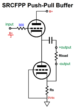
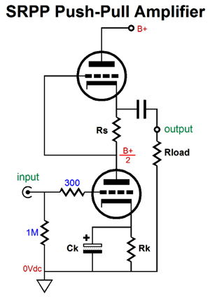
Simple Tube Math In my last post, we saw what were an SRCFPP circuit's peak positive and negative current swings into the external load impedance. I posted schematics rather than formulas.
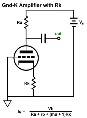
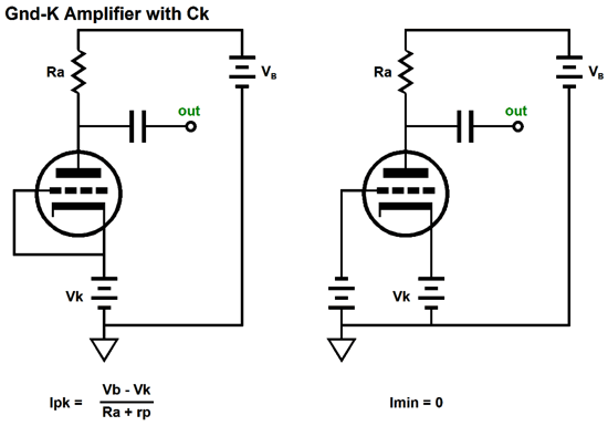
The more think about this approach, the more I like it, as it quickly shows the maximum peak positive and negative current swings into the external load impedance. This approach, however, could use some refinement, which would make it more universal and not specific to just the ECC99 in an SRCFPP circuit with a B+ voltage of 160Vdc and a load resistance of 300 ohms. But let's warm up first and start with something altogether more simple: the grounded-cathode amplifier. The first question is, How do we determine the idle current when a cathode resistor is used?
As we can see from the above formula, the larger either the rp or the plate resistor or the cathode resistor resistance, the lower the idle current; the higher the B+ voltage, the higher the idle current will be. Knowing what the idle current is essential to know what the peak output swings can be. Now, how do we determine the maximum peak positive and negative voltage swings at its output? Other than by building up the circuit and measuring the results? If we set the triode's idle current by using a capacitor-bypassed cathode resistor, the following peak and minimum currents obtain.
The above assumes that we impose a grid voltage limit of 0V; in other words, no positive grid voltages. The negative peak output voltage swing is equal to the remainder of the peak current flow minus the idle current flow against the plate resistor's resistance. For example, assume an Iq of 10mA, a Ra of 10k, and peak current flow of 15mA. Subtracting the 10mA of idle current from the current peak of 15mA yields us 5mA, which against 10k equals -50Vpk. If we know the idle current flow, then we know what the peak positive output voltage swing must be, as this voltage swing must equal the idle current against the plate resistor's value. For example, if the idle current equals 10mA and the plate resistor is 10k, then 0.01A x 10k = +100Vpk. In other words, this grounded-cathode amplifier can swing more positive volts than it can swing negative volts. In order to get symmetrical swings, we must set the idle current to half of the peak current flow. (Adding an external load resistance or forgoing the bypass capacitor on the cathode resistor will complicate the math a tad.) The quick recipe for the maximum potential voltage swings from a grounded-cathode amplifier with fixed bias (i.e. no cathode resistor) is to make Ra equal to twice the rp (the triode's plate resistance) and set the Iq (the idle current) to Vb/3Ra. See Grounded-Cathode Amplifier PDF for more details. Let's now return to the more complex SRCFPP circuit and its peak current swings.
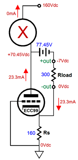
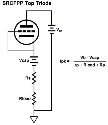
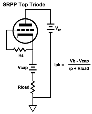
Our goal is to figure out what the extreme swings of current are possible into the external load impedance. Once we know these, we can easily find the extremes of the voltage swings, as current against resistance equals voltage. Let's start with the peak positive current swing, when the top triode is fully engaged and the bottom triode falls out of the equations, as the bottom triode is cutoff completely.
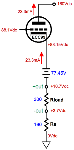
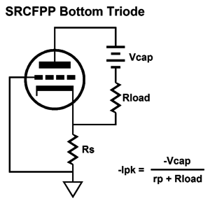
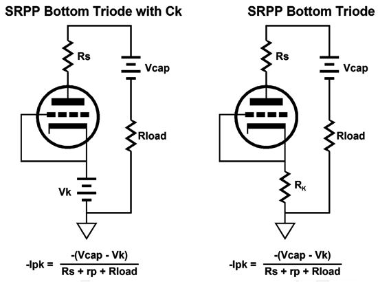
The peak negative current swing is shown below.
In both examples, Vcap is the voltage drop across the coupling capacitor. How do we find Vcap? We could measure it in reality or we could assume that it is equal to half of the B+ voltage, which is pretty much what it should be if we have set things up correctly. Note that resistor Rs falls out of the mix, as it falls out of the current circuit (current loop). Let's now move on to the SRPP circuit and its peak current swings.
Once again, our goal is to figure out the extreme swings of current that are possible into an external load impedance. Assume that the bottom triode's grid sees a negative voltage low enough to turn off the triode's current conduction entirely. The top triode would then see a grid voltage equal to its cathode voltage, so it would greatly increase its conduction.
The current-sense resistor, Rs, sees no current flow, as it is not inside the current-loop made up of the triode, the charged-up coupling capacitor, the external load, and the B+ power supply. Now we assume that the bottom triode's grid sees a positive input signal great enough to bring the grid voltage up to the cathode voltage and, as a result, turn off completely the top triode, as its grid becomes sufficiently negative relative to its cathode to cut-off its current conduction.
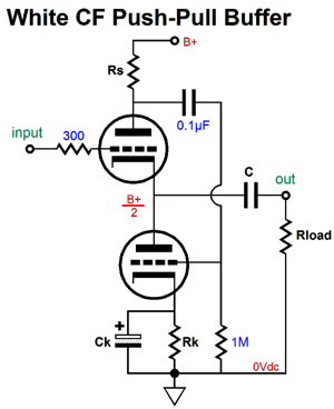
The schematic on the left assumes a large-valued bypass capacitor for the cathode resistor, while the one on the right assumes no bypass capacitor. These two circuits, the SRCFPP and SRPP, have a third brother circuit, the White cathode follower. Let's find its peak current swings.
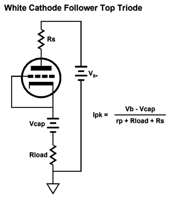
We assume that the cathode resistor receives a large-valued bypass capacitor. Let's start with the maximum peak current swing into the external load impedance, so the top triode is fully on and the bottom triode fully off.
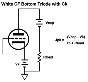
Now, the top triode is cutoff and the bottom triode is fully on.
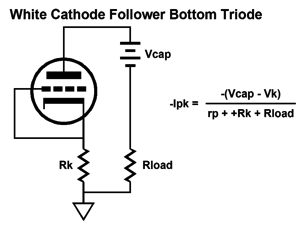
What if we didn't use a cathode-resistor bypass capacitor? Then the following schematic and formula is needed.
Understand that if we do not use a cathode-resistor bypass capacitor, then the current-sense resistor, Rs, must be larger in value.
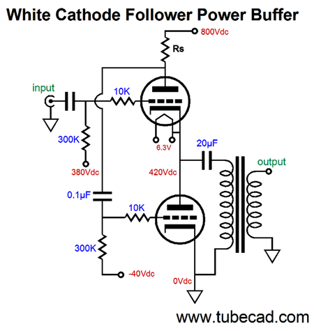
White Cathode Follower Power Buffers
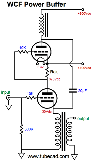
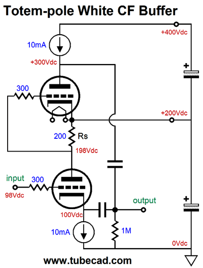
Now, let's get a bit more creative. The circuit below has placed what would be the bottom triode, the slave triode, atop the normally top triode, the driven triode.
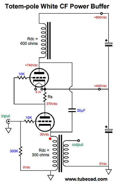
If it does not look like it can work, the reason is to be found in the +400Vdc connection, which is not a test point, but a power-supply rail, which should, much like the ground connection, offer a nearly zero-ohm impedance. The following schematic makes this point.
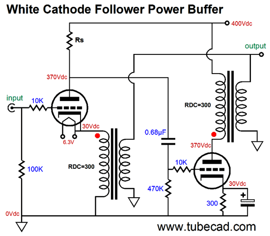
No coupling cap is used between the current-sense resistor and the top triode's grid and the inductor load functions like a constant-current source. The 20µF capacitor bridges the plate and cathode, so that both work into the output transformer primary. Alternatively, we could use two output transformers.
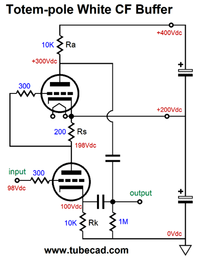
Two big advantages obtain here: no 20µF coupling capacitor and no choke. I have mentioned before that finding a high-quality inductor is difficult. In contrast, finding a good single-ended output transformer is comparatively easy. Perhaps, I am going too fast here, so I will back up a bit. Let's lose the output transformers and use resistors in their place.
Start by ignoring the top triode and focus on the bottom triode. It functions like a cathode follower. It offers a low output impedance and low distortion but no voltage gain; in fact, it suffers a small insertion loss. As the current flow varies through this triode, the current-sense resistor, Rs, develops a varying voltage drop, which directly couples to the top triode's grid. If the bottom triode's current conduction increases, the top triode's grid sees a negative voltage swing, which will decrease the top triode's current conduction, causing its plate voltage to rise. Thus, the bottom triode's cathode and the top triode's plate both are in voltage phase, although the two triodes function in anti-current phase. This means as the bottom triode pulls up, the top triode lets go and its plate resistor pulls up as well. When the bottom triode lets go, reducing its current flow in other words, its cathode falls in voltage, as its cathode resistor pulls down. At the same time, the decrease current flow through resistor Rs cause the top triode's grid to move up positively, so the top triode conducts more current, causing its plate to be pulled down. Push-pull operation in a nutshell. Now, let's replace the resistors with constant-current sources.
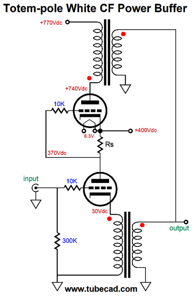
The pushing and pulling become more efficient and twice the idle current can be delivered into an external load resistance. This variation is, however, only half as efficient as a comparable White cathode follower with half the B+ voltage. The transformer-coupled version is also twice as efficient as the constant-current version, as an output transformer functions much like a constant-current source, but without the large wasteful voltage drop. One big problem with the totem-pole White cathode follower that uses two output transformers is the high B+ voltage. Well, rather than go vertical and upside-down, we can go horizontal.
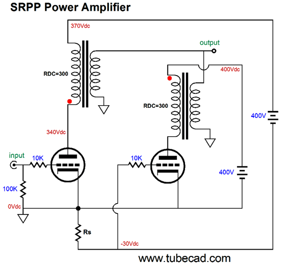
Both triodes see the same cathode-to-plate voltage and both work into the same load impedance. While drawing the above schematic, the following SRPP power amplifier came to mind.
Two power supplies are required: one fixed and one floating. The input triode o the left gets the floating power supply. Here floating means not tied to ground. As the input tube conducts more current, the voltage drop across resistor Rs grows in voltage, which then lowers the slave triode's (the right triode's) current flow. Once again, push-pull operation. Actually, this new design is so new that I am not altogether sure that it will work. Perhaps, I have the phasing wrong on the transformer? One thought is that a push-pull output transformer, one without an air-gap, could be used, as long as it held two separate primary windings. Note how there are two separate current circuits in the above circuit, one for each output triode. The two secondaries bridge the two outputs into a single output. What should you conclude here? If nothing else, you should realize that getting push-pull operation from an unbalanced input signal is possible. Of course easier solutions present themselves, such as the following circuit.
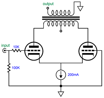
Like the SRPP, SRCFPP, and White cathode follower, the above circuit must be run in strict class-A. No doubt that there is hidden complexity within the constant-current source. Still, the concept is simple enough. In fact, the CCS could be replaced by an inductor with a few hundred-ohm DCR. The remaining question is, Is using an unbalanced input signal really an advantage? For the lazy, the answer is obvious: Yes, Yes, Yes. The big problem with most lazy solutions is all the extra work they require. For example, look at the above SRPP schematic. If we created a balanced set of anti-phase input signals, we could use a conventional push-pull, transformer-coupled output stage.
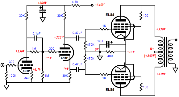
In other words, by forgoing a phase splitter, we have made the output stage needlessly complicated. Was that a wise move? The following is a complete simple push-pull power amplifier. Extra bells and whistles could be added, but as it is, it works well.
So why did I explicate these three "lazy" push-pull topologies? In this case, I did so to show what is possible, not necessarily to show what is preferable. Understanding in itself is desirable and the more topologies we can hide up our sleeves, the better.
*Dyscalculia
Next Time
User Guides for GlassWare Software Since I am still getting e-mail asking how to buy these GlassWare software programs:
For those of you who still have old computers running Windows XP (32-bit) or any other Windows 32-bit OS, I have setup the download availability of my old old standards: Tube CAD, SE Amp CAD, and Audio Gadgets. The downloads are at the GlassWare-Yahoo store and the price is only $9.95 for each program. http://glass-ware.stores.yahoo.net/adsoffromgla.html So many have asked that I had to do it. WARNING: THESE THREE PROGRAMS WILL NOT RUN UNDER VISTA 64-Bit or WINDOWS 7 & 8 or any other 64-bit OS. One day, I do plan on remaking all of these programs into 64-bit versions, but it will be a huge ordeal, as programming requires vast chunks of noise-free time, something very rare with children running about. Ideally, I would love to come out with versions that run on iPads and Android-OS tablets.
//JRB |
Kit User Guide PDFs
And
High-quality, double-sided, extra thick, 2-oz traces, plated-through holes, dual sets of resistor pads and pads for two coupling capacitors. Stereo and mono, octal and 9-pin printed circuit boards available.
Designed by John Broskie & Made in USA Aikido PCBs for as little as $24 http://glass-ware.stores.yahoo.net/
The Tube CAD Journal's first companion program, TCJ Filter Design lets you design a filter or crossover (passive, OpAmp or tube) without having to check out thick textbooks from the library and without having to breakout the scientific calculator. This program's goal is to provide a quick and easy display not only of the frequency response, but also of the resistor and capacitor values for a passive and active filters and crossovers. TCJ Filter Design is easy to use, but not lightweight, holding over 60 different filter topologies and up to four filter alignments: While the program's main concern is active filters, solid-state and tube, it also does passive filters. In fact, it can be used to calculate passive crossovers for use with speakers by entering 8 ohms as the terminating resistance. Click on the image below to see the full screen capture.
Tube crossovers are a major part of this program; both buffered and un-buffered tube based filters along with mono-polar and bipolar power supply topologies are covered. Available on a CD-ROM and a downloadable version (4 Megabytes). |
||


| www.tubecad.com Copyright © 1999-2016 GlassWare All Rights Reserved |