| John Broskie's Guide to Tube Circuit Analysis & Design |
14 March 2016
Happy Pi Day! As a young man, I was tempted to create a poster of a Biblically-correct tire that conformed to the Bible's value of pi, i.e. 3.
But after some research, I was disappointed to find that the Bible actually comes close to pi with its 3.1395348837, which is dang close; dang it.
Circlotron Output Stages
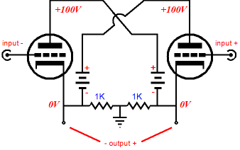
The reason, the source, the cause behind this confusion is easy to find: the power supplies are floating, i.e. not grounded. In most power amplifiers, the power supply is grounded and the external load is also grounded. In the Circlotron, on the other hand, the ground falls in between the load impedance and the two power supplies float, i.e. move up and down with the output signal. Circlotron output stages can be made from FETs, MOSFETs, pentodes, transistors, and triodes. And with the solid-state devices, we can use either two PNP or two NPN transistors; or two P-channel or two N-channel FETs or MOSFETs—exclusively, as mixing is not allowed. In fact, use of two identical output devices is a key feature of the Circlotron, as tight matching of output devices become a possibility, something that pairs of PNP and NPN transistors and pairs of P-channel and N-channel FETs or MOSFETs never truly achieve. The second key feature of the Circlotron is that both output devices see a balanced input signal equal in amplitude, but opposite in phase. Why is this a feature? The answer is found in examining other push-pull OTL topologies.
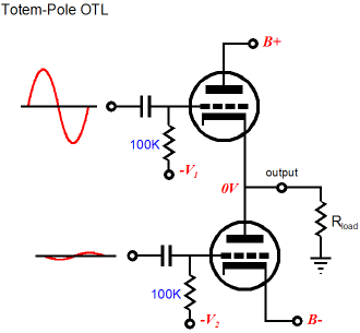
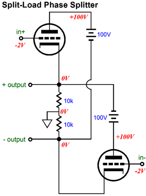
In the classic totem-pole arrangement, where one output tube sits atop another, such as in the Futterman OTL amplifiers, the top output tube functions like a cathode follower; the bottom tube, a grounded-cathode amplifier. The top tube’s grid must see a much larger input signal than the bottom tube, as the output stage’s output follows the top tube’s grid. Because the bottom tube’s cathode is grounded, in AC terms at least, its grid need only see a fraction of the input signal that the top tube must see. (Actually, things are a bit more complicated in a well-designed totem-pole OTL, as both output tubes can be made to function as either cathode followers or grounded-cathode amplifiers, depending on how the output is fed back into the phase splitter.) In the Circlotron, both output tubes function identically, but not as cathode followers. What? That is right: not as cathode followers. Nor do they function as grounded-cathode amplifiers. Well what do they function as then? A split-load phase splitter is the answer. See blog number 254.
The Circlotron is fundamentally a push-pull arrangement of two split-load phase splitters; a blanced split-load phase splitter, in other words.
A grounded-cathode amplifier can deliver a gain up to the value of the triode’s mu. A cathode follower can deliver a gain close to unity. And a split-load phase splitter can deliver a gain, differentially, close to 2. Likewise, a Circlotron can deliver a gain, differentially, close to 2.
Think about it, in AC terms, the two floating power supplies in a Circlotron are dead shorts, presenting (ideally) zero impedance to AC signals. Thus, the external load impedance effectively is in parallel with both output tube, bridging cathode to plate, with the signal grounded located mid load impedance.
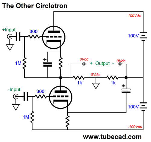
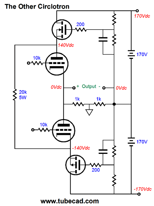
The Other Circlotron
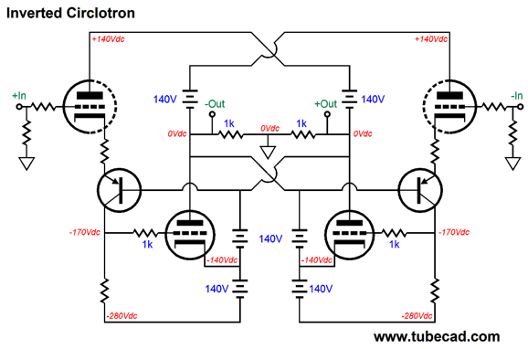
The output tubes cathodes sit at -100Vdc. Although it looks wrong, this inverted Circlotron works identically with the conventional Circlotron, delivering the same power output and distortion and output impedance. So, why bother with this inverted version? It allows us to create new topologies, such as the one I created for blog number 137, shown below.
The tube-based driver stage works to keep the output tubes under control, thereby reducing both distortion and output impedance. We can also make an inverted version that uses tube output devices, as shown below.
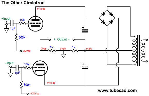
Note that in both of these inverted Circlotron circuits no capacitors appear. (Which scares the hell out of me, as DC coupling through with tubes often results in catastrophe, as tubes can go bad or go missing from their sockets or get wiggled in their sockets.) A third configuration of the Circlotron is possible, which I call the Other Circlotron. (Perhaps a better name would be the Totem-Pole Circlotron.)
The ground still falls between the external load impedance; the power supply still floats; and both output tubes receive equal-amplitude input signals. This Other Circlotron performs identically to the conventional version, as it delivers the same distortion, output power, and output impedance as the conventional version, given the same tubes and the same cathode-to-plate voltages. Unlike the conventional Circlotron, however, this totem-pole version can use one power transformer secondary per channel, as long as the secondary is center tapped. In contrast, the conventional Circlotron requires two independent secondary per channel. Okay, John, if this Other version of the Circlotron performs no better than the conventional version, why bother with it? A good question. One answer is that since high-voltage, center-tapped secondaries are so common, we can put them to some use with the Other Circlotron. In addition, my goal has always been to expand the universe of useful tube circuits, not constrain it to a few hoary topologies.
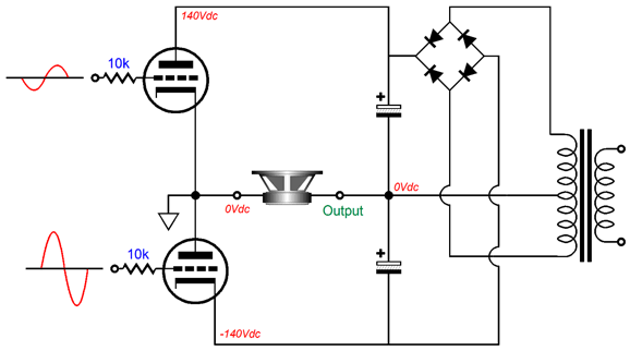
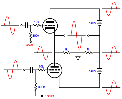
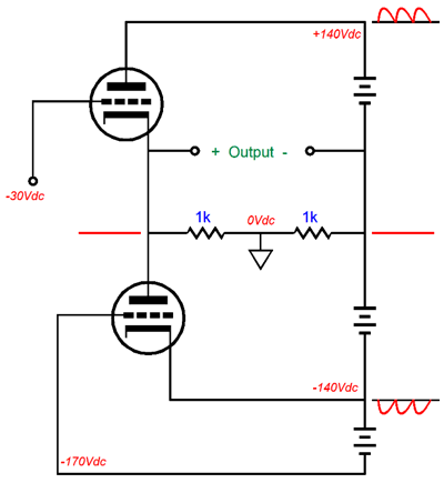
Mind you, we could invert this setup by grounding the cathode and letting the bipolar power supply float, as shown below.
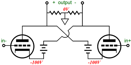
Now the top output tube functions as a grounded-cathode amplifier, while the bottom tube functions as a cathode follower, as its cathode follows its grid. Now, what happens if we split the difference between these two topologies by placing the ground mid the external load? We end up with the Other Circlotron.
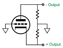
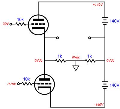
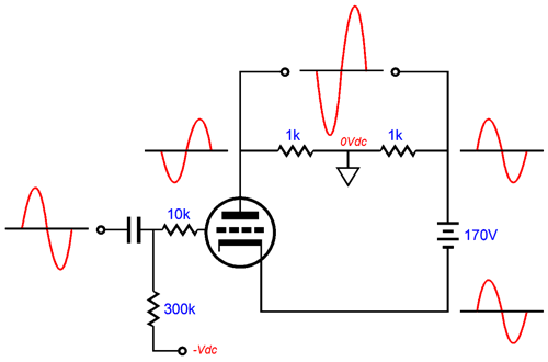
Both the top and bottom output tubes see their cathodes follow their grids, albeit in anti-phase from each other, which allows push-pull operation. Here is the basic Other Circlotron output stage at idle.
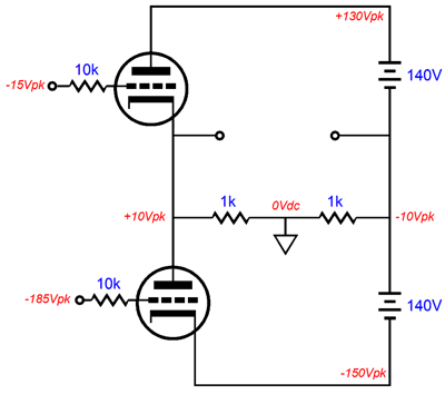
Each output tube sees the same grid-to-cathode voltage, and each draws the amount of current, so the outputs rest at 0V. Now, let’s shift the top tube’s grid up by 15V and the bottom tube’s grid down by 15V.
The external load will see a 20V voltage differential. Now, let’s shift the top tube’s grid down by 15V and the bottom tube’s grid up by 15V. Once again, the external load sees the same 20V differential, but with the current flowing in the opposite direction.
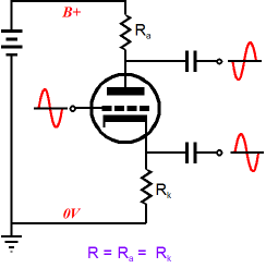
Note that each grid saw a 15V change, but 20V of change resulted at the output. With no no external load impedance, the actual output would be closer to 30V. With an 8-ohm load, we might see only 10V of differential output. Also note that each triode functions in a split-load phase splitter topology. For example, let's just look at the top triode.
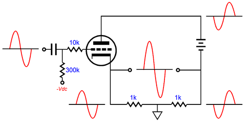
A positive input signal causes the cathode to rise in voltage and the plate to drop in voltage. The load sees differential between these two opposed voltage swings. Now, let's look at the bottom triode.
A positive input signal causes the cathode to rise in voltage and the plate to drop in voltage, just as id in the previous example. Now, in your mind's eye, combine these two circuits to form the Other Circlotron.
A Problem with the Other Circlotron
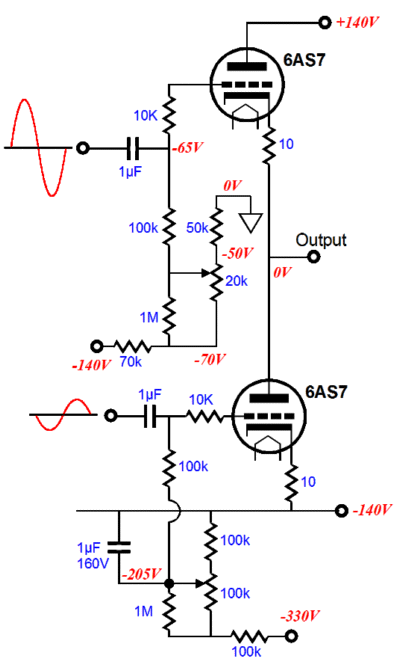
So, unless the input signal presented to the bottom output tube is equally contaminated by the negative-rail power-supply noise, the noise will be treated as input signal and amplified. One workaround that works with cathode-biased tubes is the following.
Both cathode resistors are bypassed by a capacitor, but the bottom triode’s cathode resistor is bridged to the negative output terminal, not the ground or the negative power-supply rail. Each by pass capacitor must share the same capacitance value, but can differ in voltage rating, as the top capacitor will see only fraction of the voltage that the bottom bypass capacitor will see. This setup works well with class-A operation of the output tubes, but not with class-AB operation, as the bypass capacitors will become over charged, which will reduce the idle current flow after a crescendo; in extreme cases, the overcharged capacitor can completely shut off the tube at idle. Another workaround is to use two capacitor-multiplier circuits.
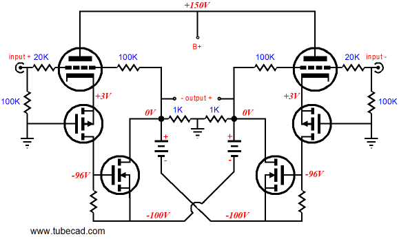
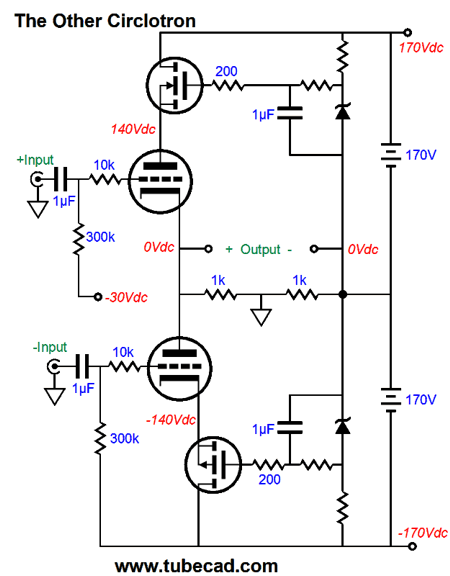
The N-channel and P-channel MOSFETs shield both the top tube’s plate and the bottom tube’s cathode from power-supply noise. Unlike the cathode resistors, these MOSFETs can work with class-AB operation. One small tweak is needed, however, as the MOSFETs should never be completely cut off, even if the tube it feeds is cutoff, otherwise switching glitches and oscillations can occur (which is often a problem in class-G power amplifiers). Fortunately, there is a simple one-part solution.
The 20k power resistor creates a current path to keep the two MOSFETs conducting at all times. An additional tweak would be to replace two resistors with zeners, so a fixed B+ and B- power-supply rail voltages are established.
Note how the bottom output tube is effectively cathode biased.
Next Time
User Guides for GlassWare Software Since I am still getting e-mail asking how to buy these GlassWare software programs:
For those of you who still have old computers running Windows XP (32-bit) or any other Windows 32-bit OS, I have setup the download availability of my old old standards: Tube CAD, SE Amp CAD, and Audio Gadgets. The downloads are at the GlassWare-Yahoo store and the price is only $9.95 for each program. http://glass-ware.stores.yahoo.net/adsoffromgla.html So many have asked that I had to do it. WARNING: THESE THREE PROGRAMS WILL NOT RUN UNDER VISTA 64-Bit or WINDOWS 7 & 8 or any other 64-bit OS. One day, I do plan on remaking all of these programs into 64-bit versions, but it will be a huge ordeal, as programming requires vast chunks of noise-free time, something very rare with children running about. Ideally, I would love to come out with versions that run on iPads and Android-OS tablets.
//JRB |
Kit User Guide PDFs
And
High-quality, double-sided, extra thick, 2-oz traces, plated-through holes, dual sets of resistor pads and pads for two coupling capacitors. Stereo and mono, octal and 9-pin printed circuit boards available.
Designed by John Broskie & Made in USA Aikido PCBs for as little as $24 http://glass-ware.stores.yahoo.net/
The Tube CAD Journal's first companion program, TCJ Filter Design lets you design a filter or crossover (passive, OpAmp or tube) without having to check out thick textbooks from the library and without having to breakout the scientific calculator. This program's goal is to provide a quick and easy display not only of the frequency response, but also of the resistor and capacitor values for a passive and active filters and crossovers. TCJ Filter Design is easy to use, but not lightweight, holding over 60 different filter topologies and up to four filter alignments: While the program's main concern is active filters, solid-state and tube, it also does passive filters. In fact, it can be used to calculate passive crossovers for use with speakers by entering 8 ohms as the terminating resistance. Click on the image below to see the full screen capture.
Tube crossovers are a major part of this program; both buffered and un-buffered tube based filters along with mono-polar and bipolar power supply topologies are covered. Available on a CD-ROM and a downloadable version (4 Megabytes). |
||


| www.tubecad.com Copyright © 1999-2016 GlassWare All Rights Reserved |