| John Broskie's Guide to Tube Circuit Analysis & Design |
25 November 2016 More
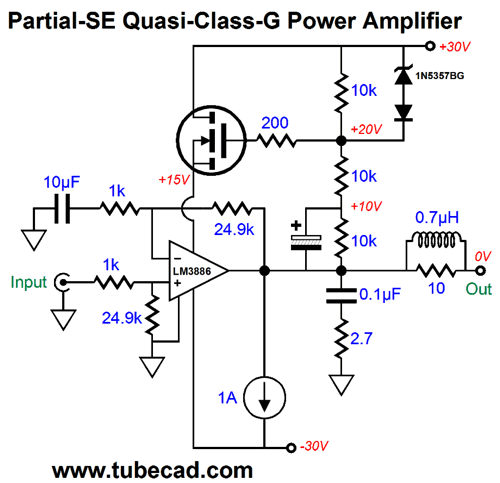
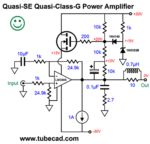
Quasi-Single-Ended Amplifier In 2002, in the Tube CAD Journal, you will find the following schematic.
This idea is old-hat to those working with OpAmps, so I wasn't claiming any new topology, let alone creating a new class of operation, rather I was pointing out that such a setup could be implemented externally to an existing power amplifier; in other words, as an add-on enhancement in its own enclosure. Of course, the huge problem is heat, as the existing power amplifier's output stage will now greatly increase its dissipation. With chip amplifiers, this problem is particularly acute, as they are relatively small and, thus, quite heat sensitive. Think about it: a power amplifier made of discrete parts might hold six output transistors per channel, each transistor being rated for 150W and each offering a thermal resistance of only 0.7C/W. in contrast, the LM3886's thermal resistance is 1C/W for the entire amplifier. The workaround I came up with is to feed the chip amplifier's positive rail voltage through a quasi-class-G setup. It's not real class-G, as only one positive power-supply rail is used, not two. (If you want, you can think of the following amplifier as being a 4W single-ended design, which can put out 36W in push-pull class-AB.)
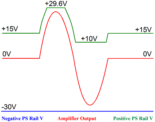
Okay, I agree that the schematic looks super complicated, but the idea behind it is simple. As the amplifier's output swings positively, its positive power-supply rail voltage rises. As the amplifier's output swings negatively, its positive power-supply rail voltage falls, but only down to about 10Vdc, where it remains until output voltage swings back up.
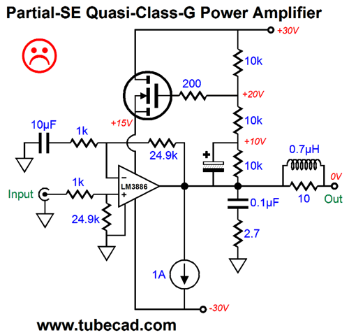
Why bother? Why not just let the positive rail voltage follow the output signal?
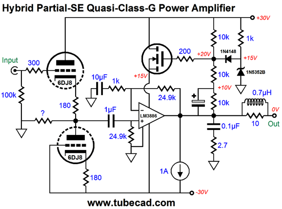
It looks good, but looks can be deceiving, as we all know all too well. The big problem here is that although the amplifier's output can swing -25V, the input stage only sees a -1Vpk input signal, but the power-supply rail positive voltage is at -12.5V. Not good. In fact, the LM3886's positive rail voltage should never fall below 9V, according to its data-sheet; thus the need for a lower voltage limit of +10V. The more that I thought about it, the more I began to worry about the zener being able to engage quickly enough, say at 20kHz. It might pass the SPICE test, but not the reality test. The workaround is to keep the zener constantly conducting, as show below.
Now, when the output swings sufficiently negative to forward bias the 1N4148 signal diode, the MOSFET stops following the output voltage. Okay, John, this is all good stuff, but where are the dang tubes? Tubes, you want tubes? No problem.
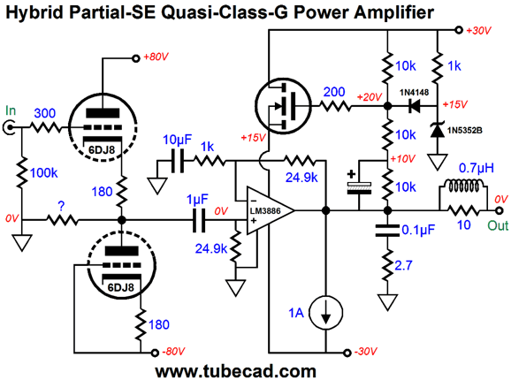
The tube-base input buffer runs off the LM3886's power-supply rails. The resistor labeled with a "?" serves two purposes. The first is to allow a path to ground for the 1µcoupling capacitor at startup, when the triodes are cold and still not conducting. The second is that allows us to force some 2nd harmonic distortion on the buffer's output. I like to run my 6DJ8 triodes, however, with a bit more than 30V of cathode-to-plate voltage. The following design uses 80V of cathode-to-plate voltage.
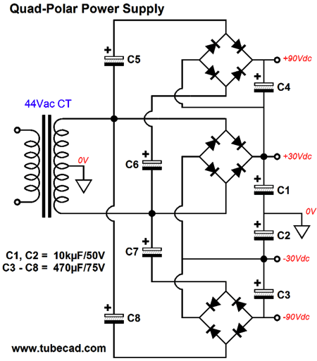
Before anyone panic, let me assure that getting the four power-supply rail voltages from a single center-tapped secondary is no big deal.
Note the +/-90 volt rails, not +/-80V rails. I assume that two RC filters would be used. A 44Vac CT power transformer would be used. Happy Black Friday. //JRB
If you enjoyed reading this post from me, then you might consider becoming one of my patrons at Patreon.com.
User Guides for GlassWare Software
For those of you who still have old computers running Windows XP (32-bit) or any other Windows 32-bit OS, I have setup the download availability of my old old standards: Tube CAD, SE Amp CAD, and Audio Gadgets. The downloads are at the GlassWare-Yahoo store and the price is only $9.95 for each program. http://glass-ware.stores.yahoo.net/adsoffromgla.html So many have asked that I had to do it. WARNING: THESE THREE PROGRAMS WILL NOT RUN UNDER VISTA 64-Bit or WINDOWS 7 & 8 or any other 64-bit OS. I do plan on remaking all of these programs into 64-bit versions, but it will be a huge ordeal, as programming requires vast chunks of noise-free time, something very rare with children running about. Ideally, I would love to come out with versions that run on iPads and Android-OS tablets. //JRB |
Kit User Guide PDFs
E-mail from GlassWare Customers
High-quality, double-sided, extra thick, 2-oz traces, plated-through holes, dual sets of resistor pads and pads for two coupling capacitors. Stereo and mono, octal and 9-pin printed circuit boards available.  Aikido PCBs for as little as $24 http://glass-ware.stores.yahoo.net/ Support the Tube CAD Journal & get an extremely powerful push-pull tube-amplifier simulator for TCJ Push-Pull Calculator
TCJ PPC Version 2 Improvements Rebuilt simulation engine *User definable
Download or CD ROM For more information, please visit our Web site : To purchase, please visit our Yahoo Store: |
|||


| www.tubecad.com Copyright © 1999-2016 GlassWare All Rights Reserved |