| John Broskie's Guide to Tube Circuit Analysis & Design |
|
28 November 2016
Even More Still: Single-Ended Designs Yet, the ride was not a comfortable one, as the transition from one large slab of concrete to another produced a thumping bump. A few weeks later we drove to a funeral, which took our car over a freshly paved asphalt road, the old-tech way of making roads, roads that didn't lay flat but were softly rounded in the center and fringed at the sides where the blacktop faded into the dirt. I remember thinking that it was a pity that the new concrete roads were not as smooth as this funky old-time road. Mind you this was back when Tang had pushed aside freshly squeezed orange juice as the breakfast drink of choice and day-glow paints seemed normal. I also remembered my beloved cat, The Mouse, whose real name was MOSFET, and whose uttered named usually included the definitive article "The," for he was truly the definitive article. (When I ran into friends, the first thing they would say was, How's The Mouse doing?" He had fans.) Well, The Mouse, like most cats and dogs, paid no attention to the sounds emitted from the stereo—until I built my first single-ended amplifier that is. Every time the first notes of music poured forth from the single-ended 10-watter, he would turn his head and attend the sonic event, evaluate it, and then finding it startling but not threatening he would return to his cat duties. How was it that he was fooled by the single-ended amplifier, but never by push-pull amplifiers, either solid-state or tube-based? Then there is the event that I described long ago in in blog post number four:
It seems that single-ended amplification hath charms to sooth the jaded ear. But why? Surely, the constant transconductance and constant output impedance lies at the heart of it, as these result in no thumping sonic bumps, which the ear finds as annoying as the eye finds a small scratch in a lenses in our glasses or the hand encountering a snag in a silk tie or nylons. We enjoy single-ended amplification and we crave more of it, as in more watts, lots more. Big class-D watts are both cheap and omnipresent; soon, toasters will sport 300W class-D amplifiers that accept Bluetooth signals. Yet, single-ended amplifiers stingily bestow only a few watts of sonic gold. I have received many e-mails asking if a cheap, powerful single-ended OTL amplifier could not be made. My reply is always the same: "A single-ended OTL amplifier is easy to design, but it won't be cheap and if it is miraculously cheap, it won't be powerful." I then go on to explain how the single-ended amplifier's idle current equals its peak output current into the load impedance and 50% theoretical efficiency of an inductively loaded single-ended output stage, which falls to 25% for constant-current loading and falls again to 12.5% for resistively loaded. The urge for OTL is obvious: the output transformer is a pain, an expensive pain. One thought I have entertained is that an autoformer falls somewhere in between an OTL and an output transformer. Wait a minute, John; are you not just swapping one big, expensive chunk of iron for another? Not necessarily, as a single-ended output transformer must sustain a continued DC current flow, which requires an air-gap and much more iron than the output watts would seem to imply. In contrast, an autoformer is much more like a push-pull output transformer, as it cannot sustain DC current flow and it holds no air-gap. Unlike a push-pull output transformer, the autoformer holds a single winding, which reduces the DCR losses. What about the high cost? If you source an autoformer from a high-end audio company, you should expect to pay gobs of money, as the zebra-wood box it comes in does not come cheap. If, on the other hand, if you contact Edcor and ask them how much it would cost for a custom autoformer, you will be pleasantly surprised by the reasonableness of the price. An experiment worth trying is to take a toroid power transformer and see how well it works as an output transformer. I did this back in the 1980s. My findings were that as long as the secondary voltage was not too low, the toroid power transformers I tested were surprisingly good. Mind you, my goal was to find a suitable output transformer for a tube bass amplifier in a tri-ammped system, where the woofers only went up to about 250Hz. A simple test would be to take a toroid isolation transformer and wire it up thus:
The power amplifier can be either a solid-state or tube design. Because the primary and secondary share the same number of turns, the voltage the speaker sees is half of what the amplifier puts out. Thus, the speakers output falls by -6dB and the speaker experiences on one quarter of the watts that it would had it been directly attached to the amplifier. Now, if we replace the 8-ohm speaker with a 2-ohm speaker, the 2-ohm speaker will experience the full wattage that the amplifier would put out into an 8-ohm load, as this makeshift autoformer reflects the 2 ohms as 8 ohms to the amplifier's output. By the way, while on the topic of transformer experiments, I might as well mention again my trick of sonically testing output transformers without actually hooking them up to output tubes.
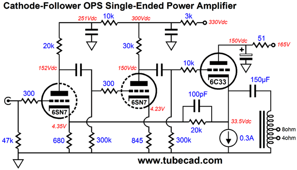
The transformer's primary impedance does not matter, as long as the two transformers are the same. The power amplifier swings out +/-10Vpk and the first transformer steps this voltage swing up to +/-200Vpk, which the second transformer steps down back to +/-10Vpk. Actually, we can expect some loss. Nonetheless, we can now compare the sound of the speaker hooked up directly to the power amplifier versus the sound of the speaker with the transformers relaying the signal. If the sound dramatically worsens or improves, the transformer isn't doing its job. Of course, since there are two transformers, each transformer only sounds half as bad as the two in series. in other words, if the highs seem to fall of only a tad, then a single transformer's high-frequency roll-off may not be too obvious. Returning to the topic of autoformers and single-ended OTL amplifiers, an autoformer that made 8- or 4-ohm speakers appears as 100-ohm loads to the single-ended OTL amplifier would result in more output watts and far less distortion. Here is one possible design.
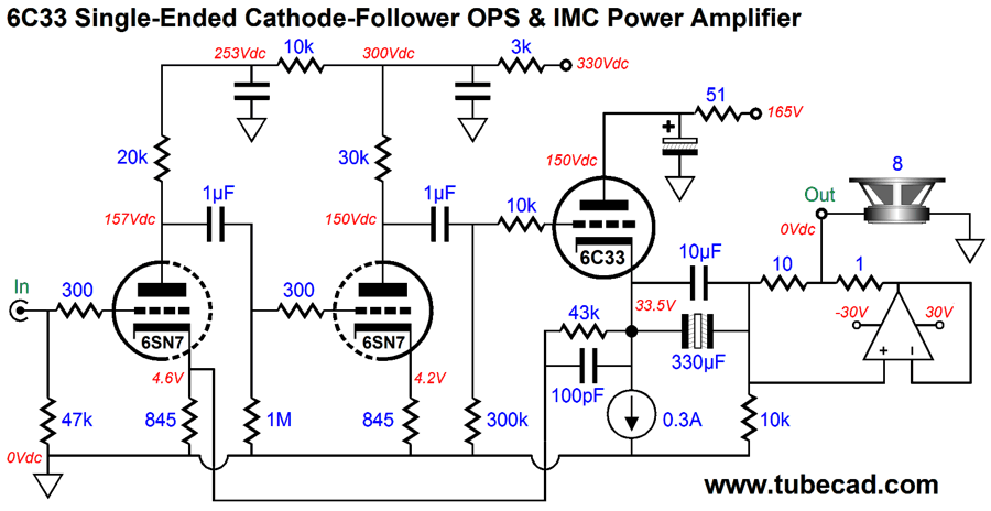
The cascading 6SN7-based grounded-cathode amplifiers develop enough gain to easily drive the 6C33 triode and fund the negative feedback loop. Since the load appears as 100 ohms, the 150µF coupling capacitor is sufficient to provide bandwidth down to about 11Hz. The phase margin is a healthy 70 degrees where the amplifier's high-frequency gain falls to unity. The output impedanceat the 6C33's cathode is about 27 ohms and the PSRR without the 51-ohm RC filter is -22dB. The distortion is not too shabby either, as shown below.
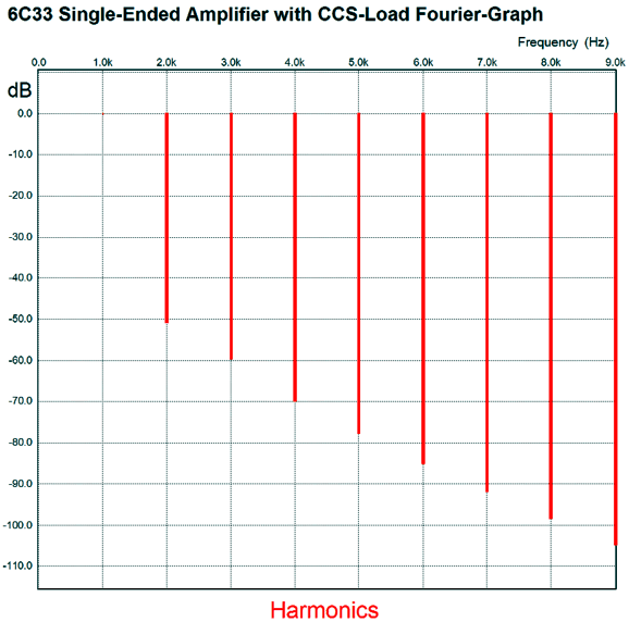
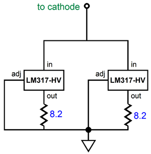
This is the SPICE-generated Fourier graph of 24Vpk at 1kHz into 100 ohms. Note the beautifully smooth downward slope of harmonics; very single-ended. The actually circuit used for the constant current source is not shown, but here is one possibility.
The LM317-HV are higher-voltage version of the standard LM317. So, how many watts can we expect from this design? We could work out the voltage and current ratios presented by the autoformer, but the easier way is to do the math with the 100-ohm impedance. The formula for average watts is W = V²/2R, where V is the peak voltage and R is the load resistance. Now, 24² divided by 200 equals 2.88W. Not much, about the same at the average 2A3 single-ended power amplifier delivers. Not enough you say? Well, we could use more 6C33 triode in parallel. Still, it would take a lot of tubes to get 25W. One workaround would be to use an impedance multiplier circuit (IMC). The following IMC makes the 8-ohm speaker appear as a 98-ohm load to the single-ended OTL amplifier. How so? The ratio of 10-ohm and 1-ohm resistors establishes an impedance ratio of (10 + 1)/1 or 11, making the 8 ohms look like 88 ohms, and to which we must add the 10 ohm resistance, bringing us up to 98 ohms.
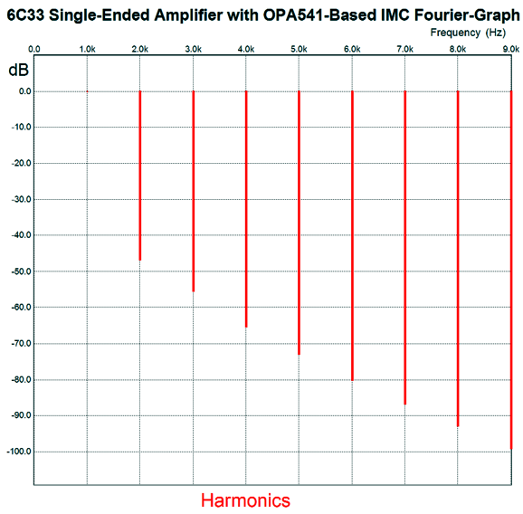
I used an OPA541 SPICE model in my simulations (the OPA541 is unity-gain stable, whereas the LM3886 is not) and the results were heartwarming (or is it ear pleasing?), as shown below, with the same 24Vpk at 1kHz, which translates into 36W into 8-ohm speakers; 72W into 4-ohm speakers.
Not bad at all. The THD distortion is only slightly greater. More importantly, the the same smooth downward slope is retained. I have covered the impedance multiplier circuit many times before, so I won't go over it again. Here, however, is a link to post number 171, which is a good place to start; Google "IMC +tubecad.com" for more.
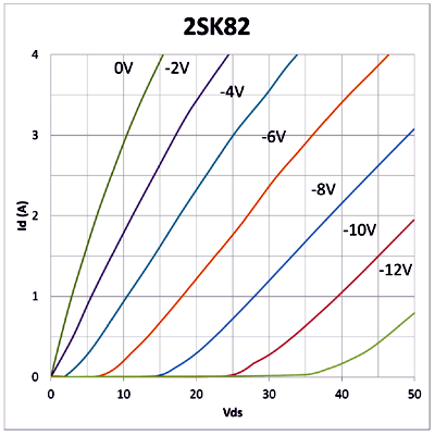
The Power FET: Sony 2SK82
This depletion-mode device differ radically from depletion-mode MOSFETs, such as the DN2530, whose drain curves are shown below. Compare the graphs and see if you can spot the difference.
Yes indeed, the 2SK82's plot-lines look very triode-like. Alas, the 2SK82 is no longer made. When Paul Norton of Linear Systems asked me what FET development would I like to see, my answer was look up the gridistor, which was developed in the early 1960s, US Patent 3407342. This FET used a solid-state analogy to the grid and cathode and plate and resulted in triode-like drain curves. (If anyone has access to an article in Solid-State Electronics from April 1967 titled, "Transition from pentode- to triode-like characteristics in field effect transistors," please send it my way. Thanks.) Using a power FET, like the 2SK82, is like using a triode—a triode that can pass many amps of current at low voltages—in that a negative gate voltage is required.
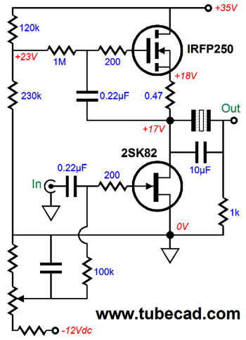
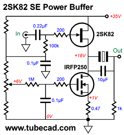
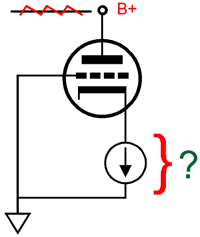
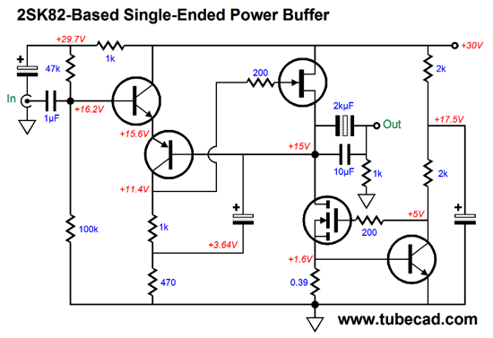
The above circuit shows the 2SK82 being loaded by one of my compliant-current source, which does not establish a fixed constant-current flow, but does present a near-infinite impedance. The high impedance shields the output from the power supply noise. The compliant-current source allows us to vary the idle current without throwing the output off its target center voltage. (This could be a real plus for those who choose to build a single-ended amplifier with two idle-current setting: light for background listening and heavy for serious listening—and showing off before friends.) Of course, we could forgo signal gain and build a power buffer, as shown below.
because the 2SK82 power SIT FET exhibits triode-like characteristics, it also suffers from triode-like problems. For example, a cathode follower that uses a constant-current load would leak how much of the power-supply noise at its output?
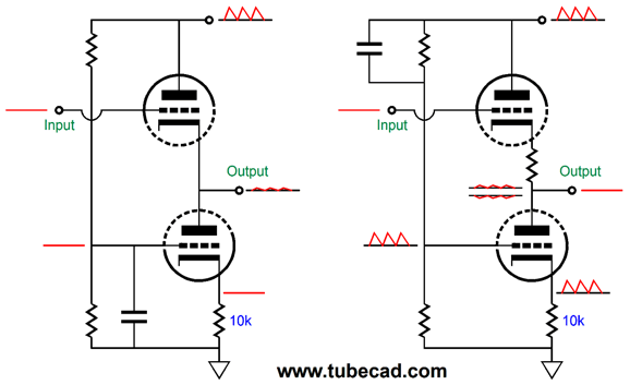
The answer might surprise you, but it will pass 1/mu of the noise at its output, where mu is the triode's amplification factor. The solution to noise-free cathode following is my Aikido cathode follower. See post 351 for more details.
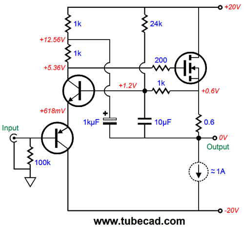
The cathode-follower circuit on the left is loaded by a constant-current source and power-supply noise appears at its output. The circuit on the right is loaded by a non-constant-current source, as the current flow is varied by the power-supply noise, and no power-supply noise appears at its output. Adding this technique to an SIT power FET source follower would look like this.
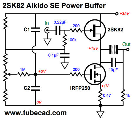
Capacitors C1 & C2 set the percentage of power-supply noise to inject at the MOSFET's gate to null the power-supply noise at the output. Another workaround is to let negative feedback eliminate the power-supply noise. The following power buffer uses a bastode input stage to control the FET's output.
This topology might look familiar, as it is an inversion of the following design from post number 353.
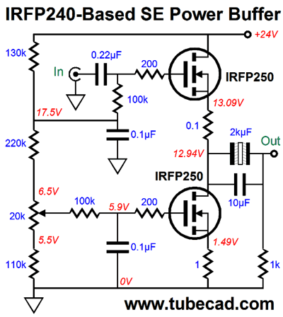
Both circuits use a bootstrap capacitor to achieve pseudo constant-current source, which increases the amount of negative feedback. More importantly, the bootstrap capacitor allows us to drive N-channel MOSFET's gate beyond the +20V B+ voltage and to drive the FET's gate below 0V; in both cases, a greater output swing results, which couldn't happen with a constant-current source. (If a constant-current source allows us to do so in SPICE simulations, it is because the SPICE constant-current source only partially mimic reality. For example, in SPICE a constant-current source is closer to being a power source, much as battery would be, than a current regulator.) By the way, it would be informative to compare the sonic results from the FET power buffer to the following MOSFET-based buffer, which would prove far cheaper to build, as the few remaining 2SK82 FETs cost a fortune.
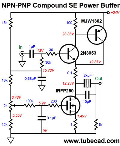
Note the 24V B+ voltage and the non-polarized coupling capacitor at the output. Many readers have written me asking about how to make use of the plentiful and fabulously cheap switch-mode power supplies sold today. The above circuit is one possibility. The idle current is set to 1.5A, so 4 to 5 amps for stereo would be a good start. I ran some SPICE simulations on the above circuit and I was not thrilled by the results, so ran some simulations on this competing power buffer.
The 2N3053 NPN transistor controls the MJW1302's current flow. Note the drastically lower resistor values used in biasing up the transistors. Here is the result of the SPICE shootout.
Clearly, the compound-transistor circuit won. Yes, John, but couldn't we apply the topology to the N-channel MOSFET? We could, but we would see less output wattage due to the much larger turn on voltage for the MOSFET. By the way, 10Vpk equals 6.25W into 8-ohm loads. I better quit this post now, although I have much more to say about singing single-ended amplifiers. //JRB
If you enjoyed reading this post from me, then you might consider becoming one of my patrons at Patreon.com. So far, 17 patrons are helping out. Join the group today.
Next Time
User Guides for GlassWare Software
For those of you who still have old computers running Windows XP (32-bit) or any other Windows 32-bit OS, I have setup the download availability of my old old standards: Tube CAD, SE Amp CAD, and Audio Gadgets. The downloads are at the GlassWare-Yahoo store and the price is only $9.95 for each program. http://glass-ware.stores.yahoo.net/adsoffromgla.html So many have asked that I had to do it. WARNING: THESE THREE PROGRAMS WILL NOT RUN UNDER VISTA 64-Bit or WINDOWS 7 & 8 or any other 64-bit OS. I do plan on remaking all of these programs into 64-bit versions, but it will be a huge ordeal, as programming requires vast chunks of noise-free time, something very rare with children running about. Ideally, I would love to come out with versions that run on iPads and Android-OS tablets.
//JRB
|
|
Kit User Guide PDFs
Only $12.95 TCJ My-Stock DB
Version 2 Improvements *User definable Download for www.glass-ware.com |
||


| www.tubecad.com Copyright © 1999-2016 GlassWare All Rights Reserved |