| John Broskie's Guide to Tube Circuit Analysis & Design |
07 January 2017 Post Number 368 New
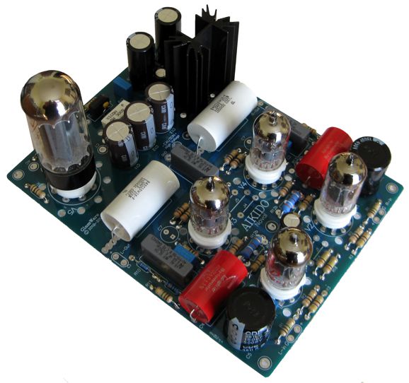
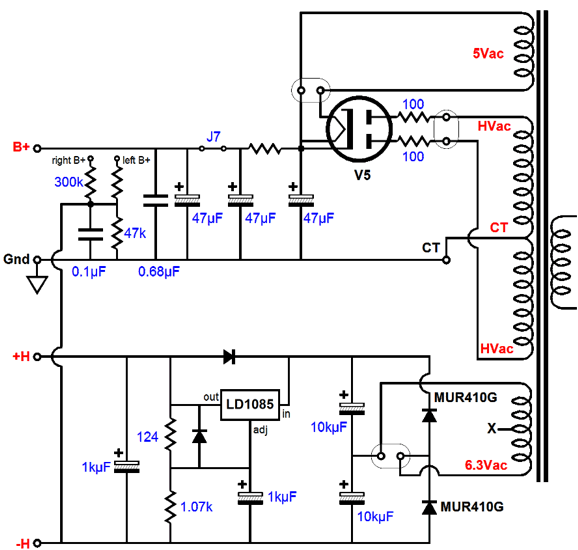
New Aikido All-in-One PCB with Tube Rectifier Here is the power-supply portion of the schematic for the new Aikido Noval PCB.
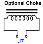
Note the three 47µF 450V capacitors, which might seem small in value compared to values used in solid-state rectified power supplies. Large values are a bad idea, however, when it comes to tube rectifiers. Why? The tube rectifier cathode cannot handle the high current spikes that a large capacitors force through rectifier's cathode. Most tube rectifier specifications state a maximum capacitor value of 50µF or 60µF, so the 47µF plays it a bit safe. In addition, the two capacitors after the RC resistor add an additional 94µF to the total capacitance. The two 100-ohm resistors at the rectifier's anodes also limit the peak surge current through the rectifier. For those who can never get enough iron, jumper J7 can be replaced by an optional external choke.
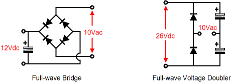
The heater power supply makes use of a 6.3Vac heater winding, which normally cannot be used to power a regulated heater power supply, as 6.3Vac rectifies up to about 7.5Vdc, which does not allow enough voltage headroom for a solid-state regulator, even an LDO type. The All-in-One's heater circuit overcomes this problem by using a voltage-doubler-rectifier circuit, which develops about 16Vdc from 6.3Vac. Here is a comparison between the full-wave bridge and full-wave voltage doubler rectifier circuits.
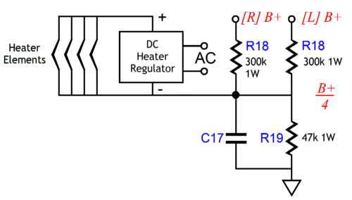
The formula for finding out how much DC current a 6.3Vac heater winding can yield in this circuit is: Imax = Iac/3.6 where Iac is the heater winding's AC current rating. For example, if the 6.3Vac winding is rated to put out 3.6A of AC current, we can get 1A of regulated 12.6V DC voltage. Resistors R18 & R19 define a two-resistor voltage divider that allows referencing the heater power supply to some positive voltage. This is an important feature when the circuit holds one triode atop another, as in the Aikido and SRPP circuits. I like to split the difference; for example, if the bottom triode's cathode sits a few volts above ground potential and the top triode's cathode rests a few volts above 100V, I would reference the heater power supply to about 50Vdc.
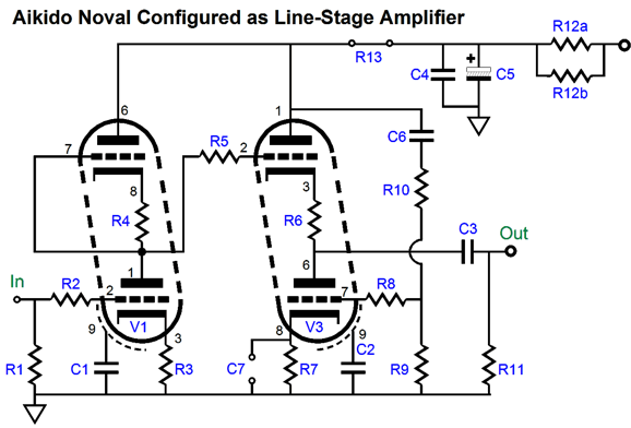
So much for the power-supply portion of the schematic for the new Aikido Noval PCB. The Aikido amplifier portion is almost identical to the Aikido Noval PCB, save for its use of only one coupling capacitor. (I had to make room for the power supplies.) Configuring Aikido Noval as a line-stage amplifier is easy enough. Resistor R13 is replaced with a jumper wire and capacitor C7 is left off the board.
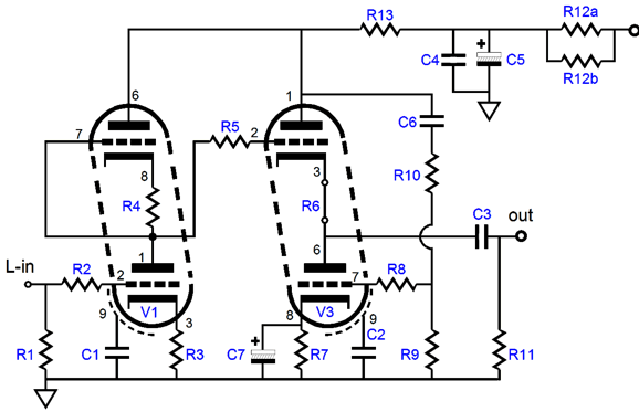
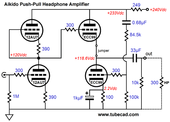
On the other hand, if you wish to build a tube-based headphone amplifier for driving high-impedance headphones, such as the 250- and 300-ohm cans made by Beyerdynamic and Sennheiser. Resistor R13 is used, but R6 is replaced with a jumper wire. In addition, capacitor C7 is used, which makes for the lowest output impedance.
The values depend on the tubes used and the load impedance. Here is one example.
Bear in mind that the ECC99 will draw 400mA per tube, so the total heater current draw on the PCB will be 1.1A, which will require at least a 6.3Vac @ 4A heater winding. This tube headphone amplifier's total B+ current draw will be about 60mA. I would use a Hammond P-T270EX transformer. Another possibility is my old favorite Hammond 6K56VG sold by Allied Electronics. Its 6.3Vac heater winding is only rated for 3.5A of current, but its 5Vac winding is rated for 3A. Since a 5Y3 or 5R4 rectifier will only draw 2A, this winding is under loaded, which allows the 6.3Vac winding to be pushed to 4A. Indeed, since the high-voltage secondary is rated for 120mA of DC current flow, twice of what we will need, the transformer will not be stressed in the least. I have bought at least five of these transformers over the years and I think they are a great bargain at less than $50 each. The formula for the Aikido push-pull amplifier's current-sense resistor is not too bad: R13 = (R9 + R10)(rp + 2Rload) / R9·mu where rp is the plate resistance of the output tube; Rload, the headphone impedance; and mu, the output tube's amplification factor.
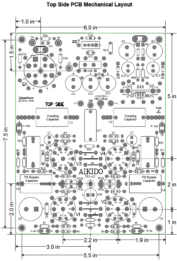
The PCB is extra thick, 0.094 inches (inserting and pulling tubes from their sockets won’t bend or break this board), double-sided, with plated-through heavy 2oz copper traces. In addition, the PCB is lovingly and expensively made in the USA. The boards are 8 by 6 inches, with five mounting holes, which helps to prevent excessive PCB bending while inserting and pulling tubes from their sockets. Each PCB holds two Aikido line-stage amplifiers; thus, one board is all that is needed for stereo unbalanced use (or one board for one channel of balanced amplification).
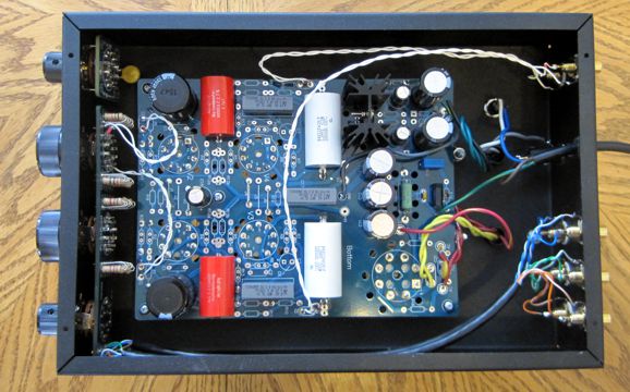
All-in-One Build Example
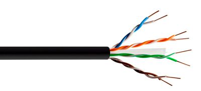
At the time, the chassis seemed plenty big, but once I began wiring it up, I wished it was a tad longer. Still, it all fit. One item that helped keep things tidy was the use of two CAT-5 cables. Several friends have told me that they have built interconnects out of CAT-5 cable and that they prefer the sound they got to that delivered by their $$$ audiophile cables. Sure, every mother's child is beautiful to her, but when I hear the same story three times, I begin to wonder if the child might not be truly beautiful. In other words, I felt it was time to try the stuff myself. One hassle I encountered was that my small supply of CAT-5 cable was in storage, along with my books, LPs, and tools. So, I went to Lowe's and bought three feet of the cable for 72 cents.
Unfortunately, the cable was designed to be used buried underground. How could this warrant the "unfortunately" label? It turns out that the four twisted pairs of solid-core wire were coated in a gooey, sticky, non-water-soluble clear gunk, which reminds me of the stuff—bio slime—they use in Sci-Fi movies to coat the alien internal organs to lend them a creepy biological realness. Yuck.
Nonetheless, the best way to keep water out is to leave no space for it to creep in, which this goo would certainly do well. Perhaps—in spite of the hassle of wiping the wires clean and repeatedly washing my hands—the vaseline-like goo might be a good idea, as it might just improve the sound. Who knows? I remember talking to a fellow who made high-end audio capacitors. He told me that he coated his polypropylene film in capacitor oil before winding the capacitors. I asked if the slick film and intense winding pressure did not force all the oil out the sides? His reply was that he first abraded the non-metalized side of the film and that he only wanted a few-molecule-thick layer of oil to remain. Who knows, he might be onto something? For those who worry about audio-grade wire, look for Plenum grade CAT-5 (or CAT-6) cable with Teflon jacketing.
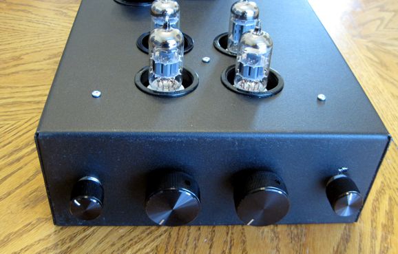
One liberating thing about not having my work space (I drilled the chassis on my garage floor with a power hand drill, which is quite powerful, but erratic) and not having all my tools, such as my Greenlee punches and rat-tail files, was that I knew that perfection was not an achievable goal. The perfect is an enemy of the actually built. Had I been aiming for perfection, I would be distraught by the scratches I made and the slightly misaligned RCA jacks. Not this time. I was just happy to have successfully built the line stage amplifier.
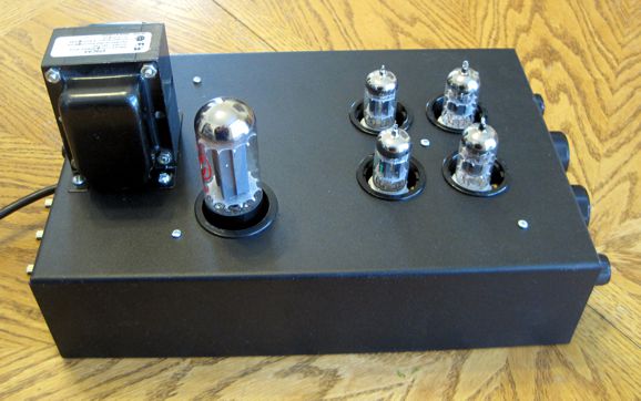
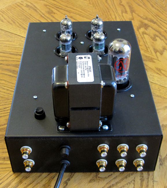
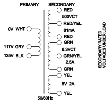
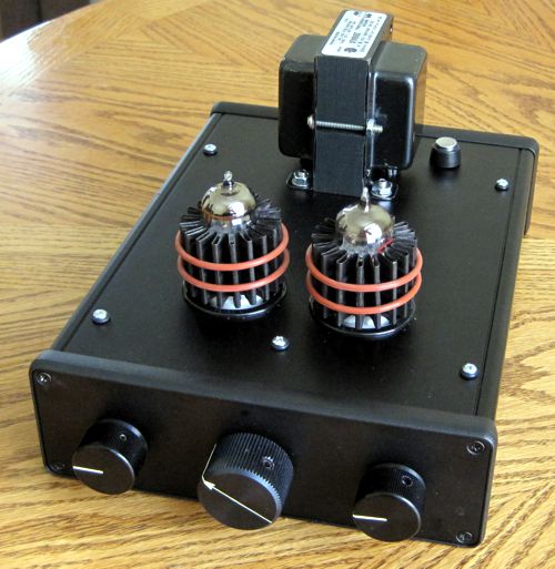
A 1A fuse appears above the power cord. I planned on using a rotary switch for an on-off switch, but the leads from the Hammond power transformer were just an inch too short. Dang. I wasn't up to splicing in extension wires, so I used a round push-button switch instead. It is located next to the power transformer. Speaking of power transformers, I used a Hammond 270CAX power transformer.
I also used a JJ 5Y3 tube rectifier and the 500Vac CT rectifies up to about 300Vdc under load, with the Aikido circuits seeing about 260Vdc, after each channels RC filter. The 2.5A heater winding is a bit wimpy, being able to deliver only up to about 700mA at 12Vdc. For this reason, I used four 12AU7 tubes, whose heater current draw totals only 600mA. How did it sound? At first, it only sounded 50%, as I was super disappointed not the hear anything in one channel. I swapped interconnects to the power amplifier, and the same channel didn't sound. I then swapped the input signals interconnects and the problem persisted. I then turned the chassis upside down and traced the audio signal from the rear RCA jacks through the selector switch and out the attenuator, then through the first stage—and all was good. So, the problem lay in the one channel's output stage. I was too loathe to remove the PCB to gain access to the parts on the other side, so I just re-soldered each solder joint on the output stage. It worked! I had undone a cold solder joint. It's been so long a time since my last cold joint that I had almost forgotten that they existed. Now, how did it sound? I thought it sounded great, so much so that I dug out my pair of NOS Telefunken 12AU7 tubes and plugged them in the input stage. At first, my reaction was exactly the same as it always is when I use these tubes: an intense letdown at the failure of my expectations. The sound does not sparkle or slam or shimmer. Yet, five minutes later, I cannot stop listening. For at least an hour I listened to the Rolling Stones. Wonderfully compelling.
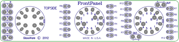
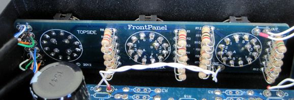
What will I do with the no longer-needed AC power switch on the enclosure's front? I am not sure. I might replace it with a Stereo-Mono switch. Sadly, I cannot use either of my Tilt-Controls. Or, I could replace the two-knob stepped attenuator with an A3-Mini. This brings up the topic of what I am using for a signal selector switch and attenuator. I am using a new PCB, the FrontPanel, which weds the Select-2 selector switch with the A5 attenuator.
FrontPanel Signal Selector & Attenuator
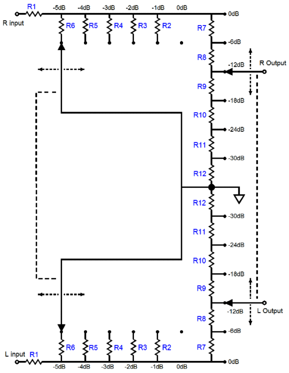
The attenuator uses both a shunt and series stepped attenuation.
As you can see, one knob make coarse -6dB steps, while a second makes fine -1dB steps; thus, the maximum attenuation is -35dB. Of course, any other set of decrements is possible, given a hand calculator and some time. I had the PCB made back in 2012, but I forgot that I had them and I only found them as a result of packing up my office recently. (2012 was the year we moved into our house, so these PCBs were lost and found in packing.)
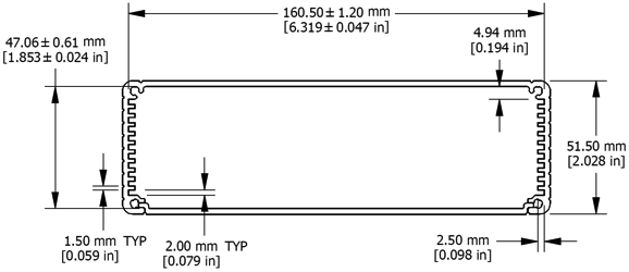
The motivation behind this design was simple: the less wiring we have to do, the better. In addition, I like using the small, 6.3in wide extruded aluminum boxes from Hammond, as in this project with a Noval ACF-2.
Yes, I do seem to use a lot of Hammond products; and, no, I do not have any connection with the company. In fact, I would like to see many changes in their product line; for example, this same extruded aluminum box but much deeper or wider would be great, as would be a power transformer with a 170Vac secondary and 4A 12Vac heater winding, for those who wish to build a robust tube headphone amplifier, as 170Vac rectifies up to about 250Vdc and a 4A winding would yield 2.2A of regulated 12Vdc. Well, the FrontPanel was designed with this 6.3in wide extruded enclosure in mind. Of course, it can be used in other enclosures. Here it is in the bigger Hammond chassis.
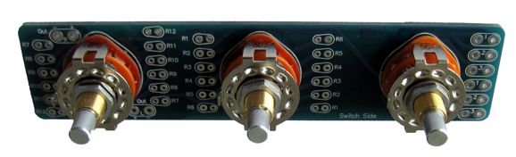
I wanted to solder the resistors on the same side as the switches, but the 1W carbon-film resistors were too long, so they are on the other side now. I almost forgot to say that the new Aikido Noval All-in-One stereo boards (and part kits and tubes) and the new FrontPanel Selector/Attenuator are available now at the GlassWare/yahoo store.
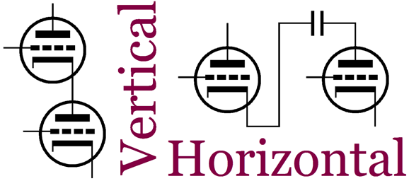
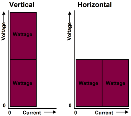
Vertical versus Horizontal
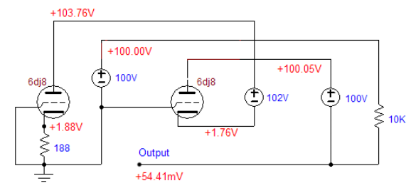
In the previous conversions from vertical to horizontal, I used floating power supplies to make the transition, as in the following horizontal cascode.
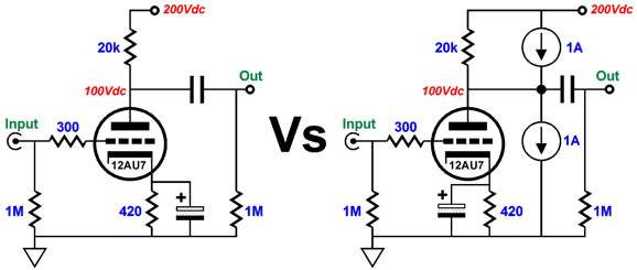
Only the power supply on the left is grounded, the other two are floating. But before you panic, let's downshift a few gears and start with an everyday grounded-cathode amplifier, as shown on the left below. This is the circuit that your grandfather would recognize. On the right, we see the same grounded-cathode amplifier, but with the addition of two 1A constant-current sources.
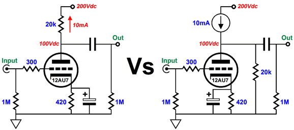
In a shootout, which circuit would deliver the most gain? The lowest output impedance and distortion? And the winner is... a perfect tie. In spite of 1W of dissipation on the left and 201W on the right, the functioning is identical. How is that possible? The two constant-current sources cancel, each presenting infinite impedance, neither dragging down (or up) the output signal. Okay, what happens if we use only one constant-current source? Once again, no difference, as both 12AU7 triodes see the same 20k load (in parallel with 1M).
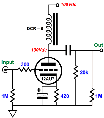
What happens if we move the 20k load resistor to the other side of the coupling capacitor?
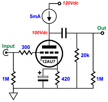
We halve the dissipation, but not much changes, as the same gain, output impedance, and distortion obtains. One possible change worth noting is that the coupling capacitor must be large enough in value to work into the 20k load in parallel with whatever external load impedance it encounters. Now, we look at one other no-difference change: inductor loading.
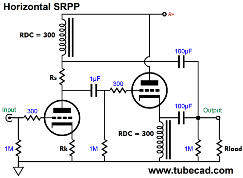
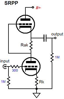
The performance is identical, but the dissipation is halved. Think of it as a parafeed grounded-cathode amplifier. Now that we have warmed up, let's return to making a vertical circuit horizontal. If we want to use one grounded power supply, which 99.9% of tube-fanciers want to do, we have to find a way to allow DC current to flow from the sole power supply, but allow AC decoupling between portions of the circuit from the power supply. An obvious choice is an inductor, as we saw in the previous example. Let's start with an SRPP circuit and make it go horizontal using two inductors.
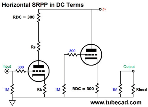
It doesn't look like an SRPP, but it is functionally identical, same gain, same output impedance, same dissipation. Here it is in DC terms.
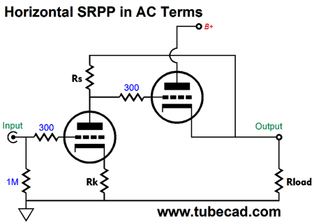
Here it is again in AC terms.
Doesn't it now look a bit more like the following circuit?
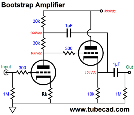
Remember that an inductor acts like a constant-current source in that it presents a supremely-high impedance, but freely allows the flow of DC current. An ideal inductor displaces no DC voltage, as it offers no DC resistance. Real inductors do. Still, 100 to 400 ohms is not that big a deal in a high-voltage circuit that draws 10mA, as it would drop only 1V to 4V. This horizontal version of the SRPP might remind you of the bootstrap amplifier topology, with good cause, as this topology is an SRPP in disguise.
This circuit's usual goal is to get as much gain as possible from the input stage. The bootstrap capacitor makes the input stage's plate resistor effectively appear much larger in value. Of course, we never get anything for free; and what we pay this time is that the cathode follower's output impedance is twice as high than you would might expect. What you might not expect is that we have left the world of strictly single-ended operation, as the input tube is actually partially driving the external load impedance—in other words, push-pull operation, albeit not optimal in terms of power output. In order to get equal current swings from both triodes, we must follow the formula, Rs = (rp + 2Rload) / mu This means that the current-sense resistor will be much lower in value and the "bootstrap" capacitor must be much larger in value.
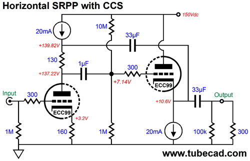
Here is a design example with an ECC99 and 300-ohm load.
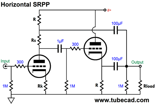
Note that the topmost 33µF capacitor terminates into the right triode's cathode, not at the output. Why? In SPICE simulations, this setup produces slightly lower distortion. With 1Vpk at 1kHz into 300 ohms, the THD was a respectable 0.18%. The output impedance came in at about 1,200 ohms and the PSRR was, however, a poor -6dB. Most importantly, we have only doubled the heat dissipation and given the output an additional 5k of load impedance to deal with. To move in the direction of intelligent horizontal, we must either use two inductors or two constant-current sources. Here is an example of the latter.
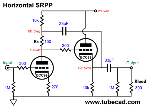
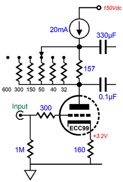
Note that the B+ is only 150V and that the idle current has been doubled. Also note the 1µF internal coupling capacitor, which could be much smaller in value, say 0.1µF instead. In order to make a standard vertical SRPP circuit would require a B+ voltage of 280Vdc. The problem with this higher voltage is that high-voltage capacitors fall off in volumetric efficiency with higher voltages. For example, a 470µF/250V capacitor finds a 450V brother, which is the size, but which holds only 150µF of capacitance, although the 450V rating is only 1.8 times higher, which would seem to imply that the 450V capacitor's value should be 261µF, not 150µF. In addition, the 33µF coupling capacitors can be rated for only 250V in the above circuit, whereas the 280Vdc SRPP would require 400V rated capacitors. Moreover, the higher B+ voltage means that the top triode's cathode will 140Vdc above ground level, which will require referencing the heater power supply to 70Vdc. On the other hand, do not imagine that the inclusion of the two constant-current sources results in a vastly improved PSRR; they don't. In fact, the same -6dB of PSRR obtains. So, other than the lower B+, was there any real advantage in moving to horizontal? Indeed, yes. We now arrive at the punch line. Going horizontal allows us to alter the current-sense resistor's value without altering the right triode's idle current. This may not appear to be a big deal, but it is. Headphones come in a variety of ohmages, such as 16, 32, 40, 50, 150, 250, 300, and 600 ohms. An SRPP that is optimized to work with 300-ohm loads will under perform with a 32-ohm load and vice versa. Because the horizontal arrangement allows us to change the value of Rs without changing the idle current or DC voltage relationships, we can use a rotary switch to select the intended load impedance.
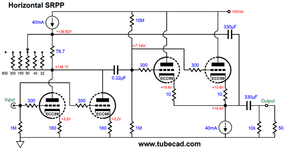
Now, if a friend brings over her headphones, you need only dial in the desired Rs value. Note the 330µF capacitor in the above schematic. Why so big? It has to be that large if 32-ohm headphones are going to be driven. Here is a deluxe horizontal SRPP headphone amplifier.
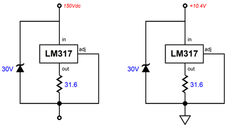
Now we are talking: 80mA of current flow per channel and a peak output current swing of 80mA, which against a 50-ohm load equals 4Vpk of peak voltage swing. Note that each constant-current source sees less than 15V, which means that we could use two LM317 IC regulators configured as constant-current sources.
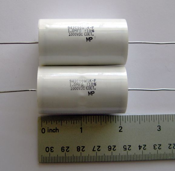
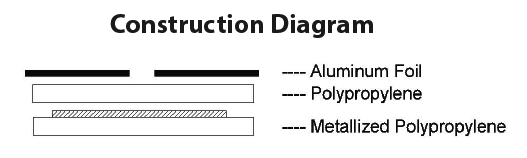
The same circuit, but placed in different positions. The 30V zener protects the LM317 without limiting the maximum voltage swing into the headphones. Another advantage this horizontal topological variation offers is that we could use a non-polarized electrolytic capacitor as the output coupling capacitor (bypassed by a quality film or PIO capacitor). Since non-polarized electrolytic capacitors stop at 100V, we could then use an audio-grade polarized 330µF electrolytic capacitor as the internal coupling capacitor (bypassed by a quality film or PIO capacitor). Because this capacitor falls on the other side of the final output coupling capacitor, we do not have to worry about the usual problem of DC leakage current from the polarized electrolytic capacitor, which makes an annoying pop sound when the headphones are first plugged in to the headphone jack. Speaking of coupling capacitors, the GlassWare store is now selling an upgraded CDE coupling capacitor: the Cornell Dubilier 942C series of hybrid polypropylene film and foil capacitors.
They are big, 54mm long and 30mm in diameter, they sound enough better than the old 940C series that the extra size and modest price increase ($20 a pair versus the old $17) are worth it. (The CDE capacitors shown in the above pictures are the smaller 940C types.)
Here is a quote from the CDE PDF:
Next Time
//JRB
If you have been reading my posts, you know that my lifetime goal is reaching post number one thousand. I have 632 more to go. My second goal is to gather 1,000 patrons. I have 976 patrons to go. If you enjoyed reading this post from me, then you might consider becoming one of my patrons at Patreon.com.
User Guides for GlassWare Software
For those of you who still have old computers running Windows XP (32-bit) or any other Windows 32-bit OS, I have setup the download availability of my old old standards: Tube CAD, SE Amp CAD, and Audio Gadgets. The downloads are at the GlassWare-Yahoo store and the price is only $9.95 for each program. http://glass-ware.stores.yahoo.net/adsoffromgla.html So many have asked that I had to do it. WARNING: THESE THREE PROGRAMS WILL NOT RUN UNDER VISTA 64-Bit or WINDOWS 7 & 8 or any other 64-bit OS. I do plan on remaking all of these programs into 64-bit versions, but it will be a huge ordeal, as programming requires vast chunks of noise-free time, something very rare with children running about. Ideally, I would love to come out with versions that run on iPads and Android-OS tablets. //JRB |
Kit User Guide PDFs
E-mail from GlassWare Customers
High-quality, double-sided, extra thick, 2-oz traces, plated-through holes, dual sets of resistor pads and pads for two coupling capacitors. Stereo and mono, octal and 9-pin printed circuit boards available.  Aikido PCBs for as little as $24 http://glass-ware.stores.yahoo.net/ Support the Tube CAD Journal & get an extremely powerful push-pull tube-amplifier simulator for TCJ Push-Pull Calculator
TCJ PPC Version 2 Improvements Rebuilt simulation engine *User definable
Download or CD ROM For more information, please visit our Web site : To purchase, please visit our Yahoo Store: |
|||


| www.tubecad.com Copyright © 1999-2017 GlassWare All Rights Reserved |