| John Broskie's Guide to Tube Circuit Analysis & Design |
14 January 2017 Post 369
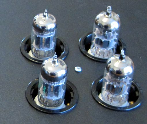
Making Big Holes in Bud Boxes
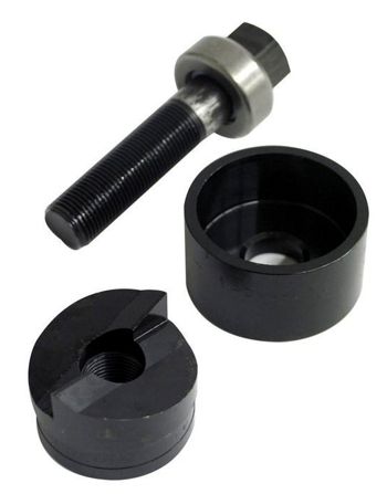
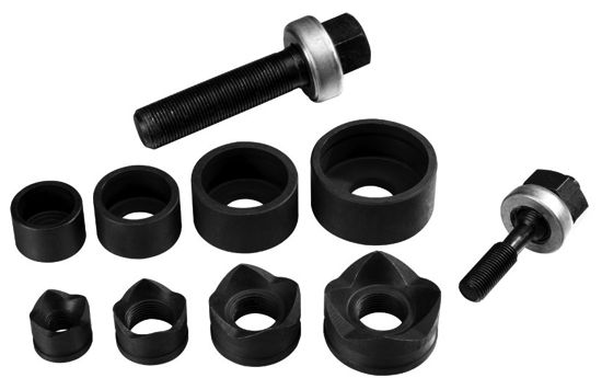
By the way, Harbor Freight sells a four-hole-punch kit for less than the price of one Greenlee punch. The only downside is that the dies are rather small: 1/2 , 3/4 , 1, and 1-1/4 inch.
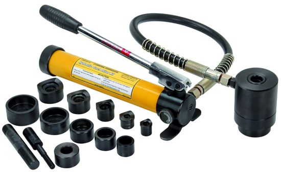
They also sell a 4 piece hydraulic punch kit for less than $100, which can make up to a 2-3/8 inch diameter hole. Amazingly cheap.
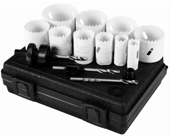
In fact, I think I just might pick this kit up today. Another Harbor Freight option is their 3/4 In to 2-1/2 inch bi-metal hole saw kit.
This is the sort of circular saw that I used to make the holes in my chassis. A hole saw, however, requires drill-press to make a clean hole. But if you must, you can use a power hand-drill. After making a hole, I like to finish the raw hole with a plastic trim ring.
(Check out boat supply stores for a selection of fancy hole trims; for example, follow this link.)
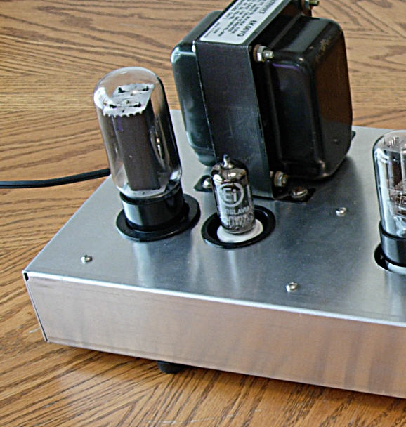
More Horizontal Transformations
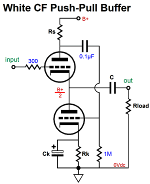
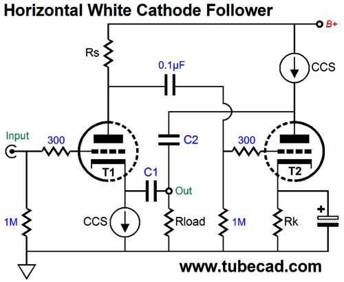
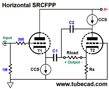
The White cathode follower is a unity-gain, push-pull buffer. Like the SRPP, it must be optimized for any given load impedance. The current-sense resistor, Rs, must equal (rp + 2Rload) / mu, as this value ensures equal current swings from top and bottom triodes. Going horizontal does not alter this situation, as the current-sense resistor plays the exact same function.
Two output coupling capacitors are needed, along with an inter-stage coupling capacitor. Capacitors, C1 & C2, should be of the same value. The cathode resistor's bypass capacitor must be far larger in value, say 1kµF. One problem we might face is that the input triode's constant-current source might get voltage starved. One workaround is to do the following.
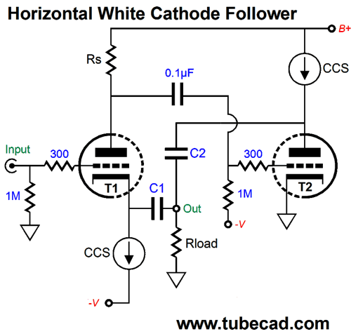
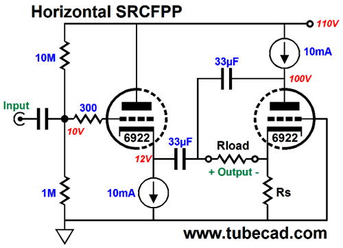
The negative power-supply rail allows us to forgo both the cathode resistor and its bypass capacitor. In addition, it gives the constant-current source all the voltage headroom it needs. Here is a fleshed-out example.
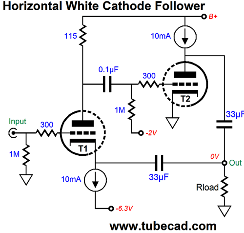
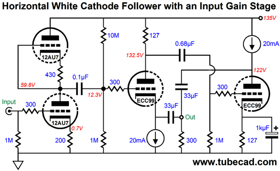
Triodes, T1 & T2, are assumed to be 6DJ8 types and the B+ voltage can be a low 110V to 120V. The external load impedance is assumed to be 300 ohms. Since the buffer offer no signal gain, we might need to add a gain stage.
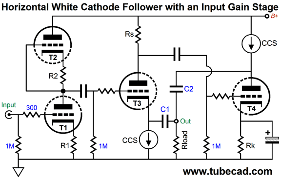
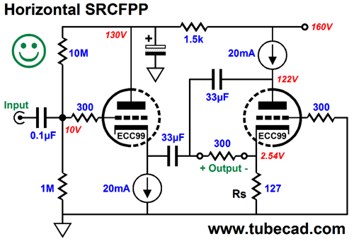
No, it's not an Aikido gain stage; it's just a grounded-cathode amplifier that uses an active load in place of a plate resistor. Here is a fleshed-out example.
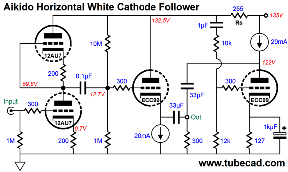
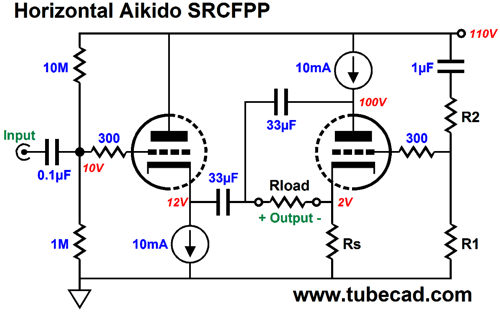
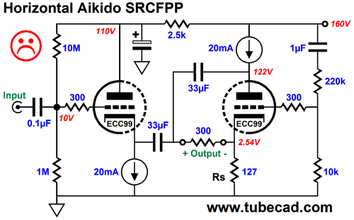
Making the move to an Aikido version is simple enough.
The right ECC99 triode's grid now sees about half the power-supply noise and the 12AU7-based input stage is enclosed within the current-sense resistor's purview. The result is a fantastically improved PSRR figure. Note how the current-sense resistor's value no longer conforms to the old formula, Rs = (rp + 2Rload) / mu.
Horizontal SRCFPP
I have already shown several horizontal SRCFPP versions in the past, the last time being in post 296, where we see this version.
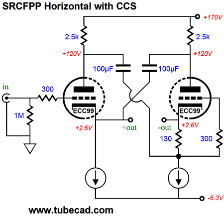
Okay, I was wrong. I just did a Google search and it revealed that the true last time was in post 337, where we see this variation on the horizontal theme. (Please read post LM337, if you need more help in understanding how it works.)
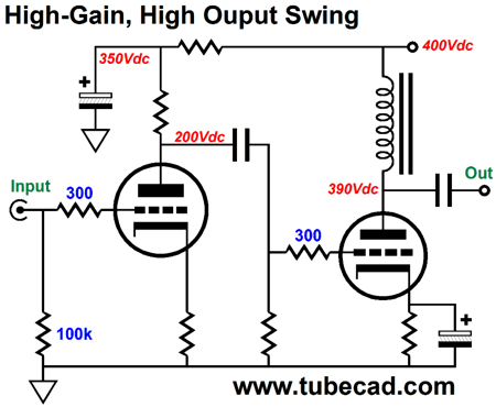
Dang, I had forgotten that I came up with this circuit. I find this topology compelling. I would love to hear it. It's a push-pull output stage that uses a single-ended output transformer. Isn't that a liability, not a feature? Not necessarily. One reason that I believe that single-ended tube amplifiers offer an advantage over push-pull tube amplifiers is found in the air-gapped output transformer, which—due to it's being stressed by the heavy DC current flow through its core— sidesteps hysteresis, the stickiness inherent in the core's flipping magnetic polarity; or, as the dictionary informs us, "the lagging of an effect behind its cause, as when the change in magnetism of a body lags behind changes in the magnetic field." In a typical tube push-pull amplifier, the output transformer's core flips magnetic polarity once per sinewave. In contrast, a single-ended amplifier's output transformer's core is constantly magnetized in one direction only, as the current may alter, but it never reverses direction. Returning to this output stage, which is a buffer, the input and driver stage must deliver a huge output voltage swings, say +/-240Vpk, which does not fit within the 400V B+ voltage. What to do? The easiest solution is to use an inductor as the plate load on the driver stage.
The inductor will displace some voltage due to its DCR against the driver triode's current draw. Note that +390V is a truly hot plate voltage. A 6SN7's plate-voltage limit is 450V and the ECC99's is 400V. The inductive load allows the driver triode's plate to swing far beyond the B+ voltage. Two constant-current sources can be used to make the horizontal transformation.
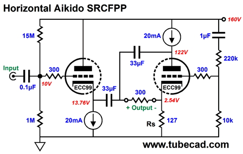
To prevent voltage starving the input triode's constant-current source we can use an input coupling capacitor and a two-resistor voltage divider.
With 12 volts, the constant-current source has no problem. The 110Vdc B+ voltage is a nice relief from the more typical 200V to 300V B+ voltages used in tube amplifiers. The net move is to insert some Aikido Mojo, which explains resistors R1 & R2.
The way it works is easy to explain. The input triode is configured as a cathode follower that is loaded by a constant-current source, so its PSRR equals 1/mu. SO, if a triode with a mu of 20 is used, then 5% of the B+ ripple will appear at the output. But if we force the same 1/20th of ripple to appear at the right triode's cathode, then the headphone driver will not see a differential voltage, so a stellar PSRR obtains.
The above schematic shows a fleshed out version. here is an example of what often happens: a reader sees the above schematic, builds it, then complains to me that the PSRR is not all that stellar. I ask to see what values he used. He then sends me the following schematic. Note the difference.
He added an RC filter tot he first triode. Why? He didn't get the the idea behind the original circuit and he figured that the more RC filters the better. I then tell him to pull out all the Aikido resistors and capacitors. This brings the PSRR back down.
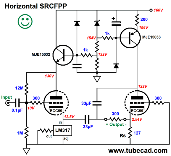
Actually, I quite this version, as it ensures equal cathode-to-plate voltages between triodes. Here is another approach.
The NPN transistor functions as an emitter follower, while the PNP transistor functions as a constant-current source. The LM317 is configured also as a constant-current source. Its resistor must equal 1.25V/A; in this example, we desire 20mA of current flow, so 62.5 ohms is needed. Since they do not make such a value, we can use a 62-ohm resistor. The two diodes are there to protect the transistors at turn-off, as they allow a discharge path for the capacitors.
Next Time
//JRB
If you have been reading my posts, you know that my lifetime goal is reaching post number one thousand. I have 631 more to go. My second goal is to gather 1,000 patrons. I have 975 patrons to go. If you enjoyed reading this post from me, then you might consider becoming one of my patrons at Patreon.com.
User Guides for GlassWare Software
For those of you who still have old computers running Windows XP (32-bit) or any other Windows 32-bit OS, I have setup the download availability of my old old standards: Tube CAD, SE Amp CAD, and Audio Gadgets. The downloads are at the GlassWare-Yahoo store and the price is only $9.95 for each program. http://glass-ware.stores.yahoo.net/adsoffromgla.html So many have asked that I had to do it. WARNING: THESE THREE PROGRAMS WILL NOT RUN UNDER VISTA 64-Bit or WINDOWS 7 & 8 or any other 64-bit OS. I do plan on remaking all of these programs into 64-bit versions, but it will be a huge ordeal, as programming requires vast chunks of noise-free time, something very rare with children running about. Ideally, I would love to come out with versions that run on iPads and Android-OS tablets. //JRB |
If you have been reading my posts, you know that my lifetime goal is reaching post number one thousand. I have 631 more to go. My second goal is to gather 1,000 patrons. I have 975 patrons to go. If you enjoyed reading this post from me, then you might consider becoming one of my patrons at
Kit User Guide PDFs
E-mail from GlassWare Customers
High-quality, double-sided, extra thick, 2-oz traces, plated-through holes, dual sets of resistor pads and pads for two coupling capacitors. Stereo and mono, octal and 9-pin printed circuit boards available.  Aikido PCBs for as little as $24 http://glass-ware.stores.yahoo.net/ Support the Tube CAD Journal & get an extremely powerful push-pull tube-amplifier simulator for TCJ Push-Pull Calculator
TCJ PPC Version 2 Improvements Rebuilt simulation engine *User definable
Download or CD ROM For more information, please visit our Web site : To purchase, please visit our Yahoo Store: |
|||


| www.tubecad.com Copyright © 1999-2017 GlassWare All Rights Reserved |