| John Broskie's Guide to Tube Circuit Analysis & Design |
22 January 2016 Post 370
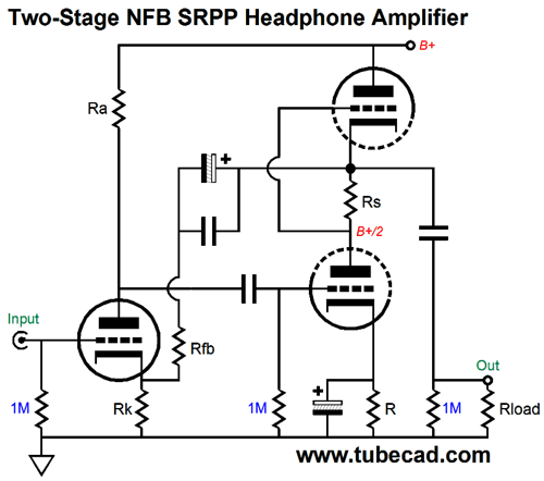
SRPP as Output Stage
The input stage, a grounded-cathode amplifier, drives the SRPP and accepts negative feedback via resistor Rfb form the output, which will reduce gain, distortion, and output impedance. (And will lessen the SRPP's sensitivity to its load impedance somewhat.) This amplifier does not invert the phase, as in electronics two cascading wrongs make a right; i.e. two cascading phase inversions cancel.
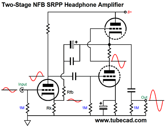
The electrolytic capacitor in the feedback loop is bypassed with a quality film capacitor. The SRPP's bottom cathode resistor gets bypassed by an electrolytic capacitor, which in turn could be bypassed by a quality film capacitor. In general, I do not like using a bypassed cathode resistor in my own SRPP builds, as an unbypassed cathode resistor results in lower distortion; but after a few SPICE simulations, I saw that the bypassed cathode resistor helped more than it hurt lowering distortion. This attests to the input stage's (and the negative feedback it provides) greater influence on the resulting output. Given a well-filtered or regulated high-voltage power supply, this mini OTL could easily drive high-impedance headphones well. Nonetheless, I would never build this circuit for myself. Why not? Other than it being too obvious, I do not like the capacitors in the feedback loop and I would prefer to use four tubes in a stereo headphone amplifier rather than three. So, what would I do instead?
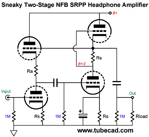
Sneaky NFB Two-Stage SRPP Amplifier
I have covered stealth NFB before. See post 286, under the section titled, OTLs and Stealth Feedback Loops.
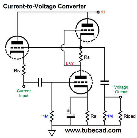
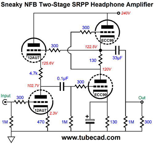
In the above circuit, the top input-stage triode's grid attaches right at the output, before the output coupling capacitor. To understand how this works just imagine that a positive voltage pulse were delivered to the circuit's output. The pulse would cause the top input triode's cathode to rise, as its grid would 100% of the pulse, which would cause the bottom input triode's plate voltage to also rise, which would force the SRPP's bottom triode to increase its current conduction, which would work to pull the output back down, countering the positive pulse. Negative feedback, in short. Another way of looking at this circuit is to realize that holds a hidden current-to-voltage Converter.
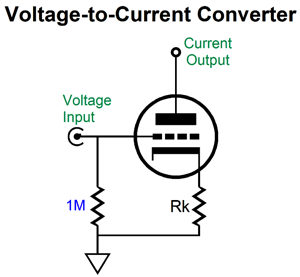
And the input triode functions as a voltage-to-current converter.
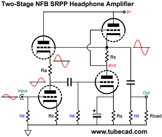
And resistor Riv sets the conversion ratio. Here is a fleshed-out design example.
The 12AU7 and ECC99 make a fun pairing. The SRPP output stage is optimized for driving 300-ohm loads, following the formula: Rs = (rp + 2Rload)/mu. (The ECC99's rp is tad less than 2300 ohms and its mu is 22 at this plate voltage and current.) In SPICE simulations, the performance was exemplary.
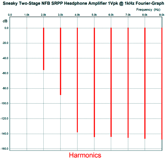
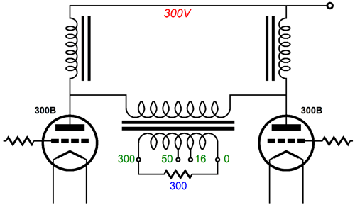
The balance between SRPP triodes was perfect. The gain came in at about 3.5 and THD was 0.17%. The PSRR was fine at better than -40dB. What about the output impedance? It came in at 135 ohms, which is amazingly-low for an SRPP-based amplifier. So, isn't this also fine? I am not so sure. What do you mean "not so sure, " as everyone knows lower is better? Yes, that is what everyone knows, but I do not know it. Maybe it is; maybe it isn't; and maybe it's both. I can easily imagine some audiophile replacing his old SRPP circuit for the one above and being disappointed, in spite of vastly improved performance specifications. How so? Perhaps the SRPP's relatively high output impedance was in fact a feature, not a liability. Several RMAFs past, I heard something that impressed me greatly, which I didn't expect. I was in the Can-Jam room, listening to Sennheiser HD-800 headphones, headphones which hitherto I was never all that impressed by. When I upgraded from the HD-580s to the HD-650s, however, I was impressed. But the HD-800s didn't sound much better—if at all—than my HD-650s, so no upgrade. (Was Windows 98 reallyu an improvement over Windows 95?) But at this RMAF, the HD-800 headphones sang. The tube-filled amplifier cost an obscene amount of money, but it made the headphones sound as if they were worth their $1,400 price tag. The fellow showing the 300B-based, balanced-out headphone amplifier didn't speak English that well, so I had a hard time gleaning what the topology looked like. It might have been the following.
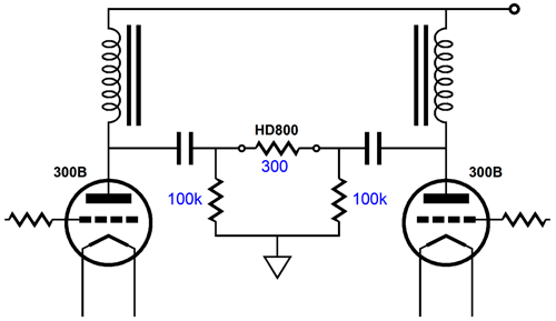
A push-pull, parafeed output stage. The two inductors act like constant-current sources and the output transformer protects the headphones and listener from the high B+ voltage. The output transformer might have been a 1:1 isolation transformer, not a step-down one. On the other hand, the circuit might have been this one.
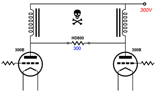
No output transformer, but the two coupling capacitors also protect us from the high voltages. In contrast, the following possibility scares the hell out of me.
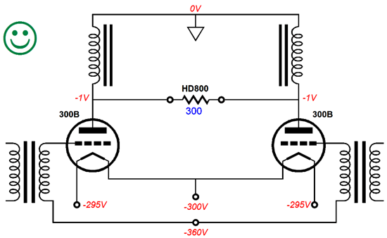
Yet, it is possible that this is what was being used. Maybe, it was something like this, instead.
Note that the balanced output sit at -1V, not +299V, in this version. The important point was that a relatively high output impedance was presented, which did not seem to hurt the sound from the HD-800 headphones, but improve it. Blasphemy, I know. My assumption is that 90% of what we know for certain is wrong, so I am comfortable with contemptuous utterances or writings concerning sacred entities, which makes me a lot of fun at a dinner party, but a nuisance in a classroom. Here is the test to perform.
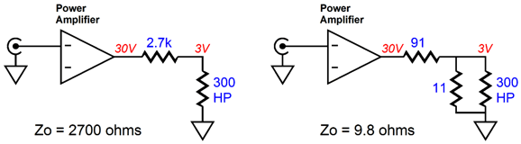
In both cases, the headphone see the same 3Vpk form the big power amplifier—but the output impedance is substantially different, 2,700 ohms against 9.8 ohms. Well, which sounds better to your ears? If it is the one on the left, then you should be building a current-output amplifier for your headphones, not a voltage-output one, effectively like the one shown on the right. (I have written much about current-output amplifiers, which a quick Google search will reveal. I would start with post 238.)
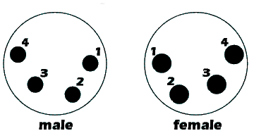
Building a current-output headphone amplifier is no harder than building a voltage output design. One wrinkle, however, is having to provide a four-contact headphone plug and jack for circuits that use a negative feedback and a current-sense resistor, such as the following.
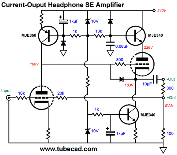
The input triode strives to maintain a fixed voltage ratio between its input signal and the signal present at the top of the 100-ohm current-sense resistor. The result is that the output impedance is low at the top of this resistor, but very high at the top of the 300-ohm headphone driver. I glibly placed the two constant-current source symbols within the above schematic, but actually implementing those two takes a bit of work. Here is one possibility.
I added an emitter follower atop the output triode to improve the PSRR. Note the high B+ voltage. If we are willing to add an inter-stage coupling capacitor, then we
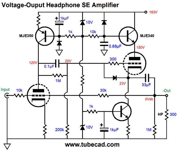
can use a much lower B+ voltage, as shown in this voltage-output amplifier below.
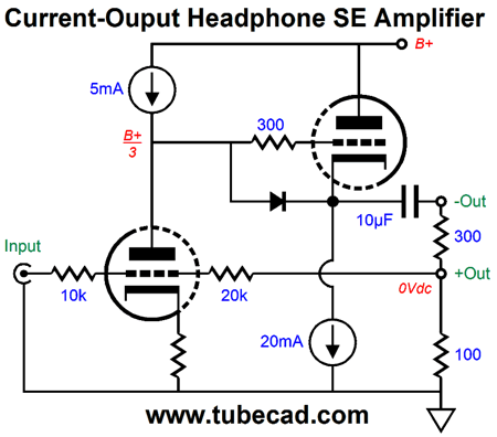
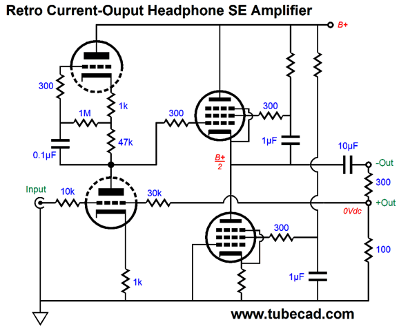
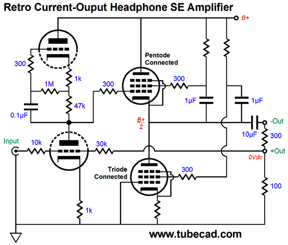
Each triode sees a healthy cathode-to-plate voltage, but only 163V of B+ voltage is needed. Returning to current output designs, I know that many prefer all-tube designs, so here is a design that could have been made in 1950.
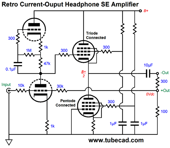
The input triode sees an active plate load and both pentodes are configured as pentodes. If the two 1µF terminated into ground, as they do in the following schematic, then the top pentode is triode-connected, while the bottom pentode remains pentode-connected.
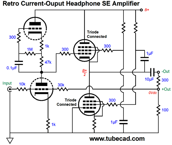
Indeed, we can triode-connect both pentodes, as shown below.
This leaves only one last possibility: pentode atop triode.
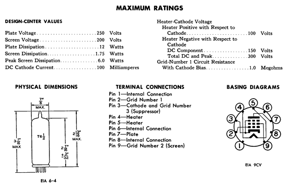
Your homework assignment to figure how many possible configurations are possible with three possible configurations of the pentodes: pure pentode, triode-connected, and ultra-linear. (About once a year, I get an email that states the reader just doesn't get how dense I can be, as he—upon surveying these four schematics—concludes that the brand of 1µF is far more important than how a pentode is configured, something of which Gilles Holst and Bernhard D.H. Tellegen can be forgiven, considering that Duelund and V-Cap did not exist in 1926, but which is unforgivable by anyone writing about tube circuits today. Surely, you can see his logic, as everyone knows that the most important aspect about a pacemaker is its brand, not its placement within your body.) The pentodes could be 6V6 or EL84 pentodes, but I would use the 6CW5/EL86 instead, as this low-voltage pentode can idle at an amazingly high idle current, say 100mA, with only a 80V cathode-to-plate voltage. In fact, this mighty but tiny pentode comes in a 15CW5/PL84 version, whose heater requires 15V at 300mA.
The assumption is that a high-mu triode, such as the 12AX7 or 5751 is used as the input tube. The 47k plate resistor's value might have to be changed to center the output stage. If a voltage-output amplifier is preferred, we need only change the feedback resistor termination, as was shown in the previous schematic.
Special Thanks If you have been reading my posts, you know that my lifetime goal is reaching post number one thousand. I have 630 more to go. I should easily be able to hit post 400 this year. My second goal is to gather 1,000 patrons. I have 973 patrons to go. If you enjoyed reading this post from me, then you might consider becoming one of my patrons at Patreon.com.
//JRB
User Guides for GlassWare Software Since I am still getting e-mail asking how to buy these GlassWare software programs:
For those of you who still have old computers running Windows XP (32-bit) or any other Windows 32-bit OS, I have setup the download availability of my old old standards: Tube CAD, SE Amp CAD, and Audio Gadgets. The downloads are at the GlassWare-Yahoo store and the price is only $9.95 for each program. http://glass-ware.stores.yahoo.net/adsoffromgla.html So many have asked that I had to do it. WARNING: THESE THREE PROGRAMS WILL NOT RUN UNDER VISTA 64-Bit or WINDOWS 7 & 8 or any other 64-bit OS. One day, I do plan on remaking all of these programs into 64-bit versions, but it will be a huge ordeal, as programming requires vast chunks of noise-free time, something very rare with children running about. Ideally, I would love to come out with versions that run on iPads and Android-OS tablets.
//JRB |
Kit User Guide PDFs
And
High-quality, double-sided, extra thick, 2-oz traces, plated-through holes, dual sets of resistor pads and pads for two coupling capacitors. Stereo and mono, octal and 9-pin printed circuit boards available.
Designed by John Broskie & Made in USA Aikido PCBs for as little as $24 http://glass-ware.stores.yahoo.net/
The Tube CAD Journal's first companion program, TCJ Filter Design lets you design a filter or crossover (passive, OpAmp or tube) without having to check out thick textbooks from the library and without having to breakout the scientific calculator. This program's goal is to provide a quick and easy display not only of the frequency response, but also of the resistor and capacitor values for a passive and active filters and crossovers. TCJ Filter Design is easy to use, but not lightweight, holding over 60 different filter topologies and up to four filter alignments: While the program's main concern is active filters, solid-state and tube, it also does passive filters. In fact, it can be used to calculate passive crossovers for use with speakers by entering 8 ohms as the terminating resistance. Click on the image below to see the full screen capture.
Tube crossovers are a major part of this program; both buffered and un-buffered tube based filters along with mono-polar and bipolar power supply topologies are covered. Available on a CD-ROM and a downloadable version (4 Megabytes). |
||


| www.tubecad.com Copyright © 1999-2017 GlassWare All Rights Reserved |