| John Broskie's Guide to Tube Circuit Analysis & Design |
|
25 July 2017 Post 389 Special Thanks If you have been reading my posts, you know that my lifetime goal is reaching post number one thousand. I have 611 more to go. I should easily be able to hit post 400 this year. My second goal is to gather 1,000 patrons. I have 959 patrons to go. If you enjoyed reading this post from me for the last 18 years, then you might consider becoming one of my patrons at Patreon.com. It would make a big difference to me. Thanks.
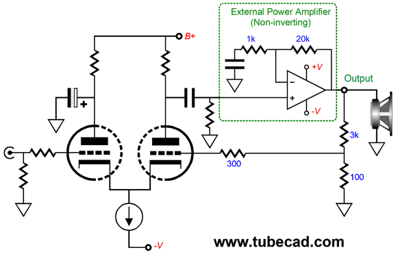
More Super-Triode Ideas Long-time reader, Stuart, wrote to me asking about how to use a triode-based differential amplifier stage to drive a gainclone chip amplifier, such as the LM4780 (which I believe is no longer in production), with a global negative feedback loop returned to the differential amplifier stage, so the triodes would control the output. Here is one possibility.
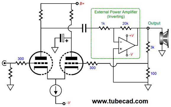
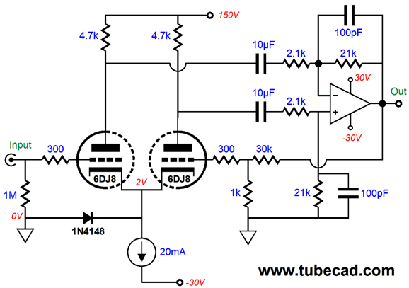
The proper name for this tube circuit is the cathode-coupled amplifier, as the left plate resistor is shunted by the large-valued capacitor to ground, so only the right plate resistor sees a signal-induced voltage swing. Alternatively, we can flip the circuit, so the right plate resistor gets shunted to ground, while the left triode drives the inverting solid-state power amplifier.
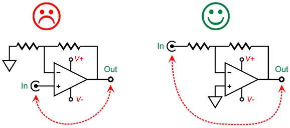
Which arrangement is best? Both preserve the input signal’s phase at their outputs. The first version offers lower input capacitance, but higher capacitance at its inverting input due to Miller-effect capacitance. The second version reverses this, so it exhibits higher input capacitance, but lower capacitance at its inverting input. Both delivered poor intrinsic PSRR, as the constant-current source loading of the tied-together cathodes results in almost zero PSRR at the output triode’s plate. The first version requires one more capacitor than the second version. I tend to prefer the second version. Why? There’s an old saying in analog electronics: Whenever possible, invert. Inverting amplifiers offer several benefits, such as being less likely to oscillate due to the input signal being contaminated by an in-phase output signal. This can be a big deal in a high-gain circuit, such as a phono stage, where miniscule input signals are greatly amplified, as an in-phase output can re-circulate through the amplifier if the output signal radiates into the input or inductively couples to the input.
Second, the power amplifier’s input stage does not banged about in the inverting configuration, as both its inputs are locked at ground potential. Third, when a capacitor shunts the feedback resistor in an inverting amplifier, the amplifier’s high-frequency output falls off at a steady 20dB per octave; not so, with a non-inverting configuration, as the drop-off plateaus at the unity-gain intersection.
In other words, inverting is cool. Still don't believe me, then listen to the master, Robert Cordell, from page 538 of his thick tome, Designing Audio Power Amplifiers:
There is a third arrangement, however, the differential amplifier topology, which combines both inverting and non-inverting operation at once.
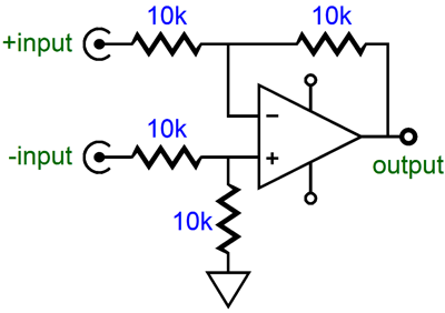
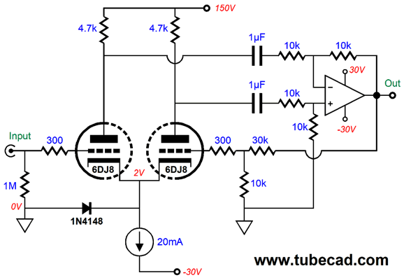
This circuit subtracts the negative input from the positive input. Present +1V to the non-inverting input and -1V to the inverting input and +2V appears at the output, as +1V - -1V = +2V. Present the same voltage, either +1V or -1V to both inputs at once and 0V appears at the output, as +1V - +1V = 0V, as does -1V - -1V. Differential amplifiers are fantastically useful circuits. Thus, my first thought was: Why not cascade one differential amplifier into another differential amplifier, as shown below.
The 30k and 10k feedback resistors that complete the global feedback loop set a total gain of 4, as (30k + 10k) / 10k equals 4, or +12dB. The solid-state differential amplifier provides a gain of 2, or +6dB. Thus, the tube-based input differential amplifier must provide a gain of at least 2 for the total gain to be achieved. With a 6DJ8 and 4.7k plate resistors, the plate-to-plate gain is about 19; plenty, in other words, to make a final gain of 4. The solid-state power amplifier receives a balanced input signal from the triode-based differential amplifier, which allows the magic of high-CMRR from the solid-state differential amplifier to result. In other words, we can vastly improve the PSRR, as the power-supply noise at the triode plates will be treated as a common-mode signal and largely ignored by the solid-state power amplifier. (See post number 75 for more details on the differential amplifier).
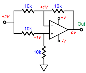
The +2V voltage presented to both inputs is 100% common-mode, i.e. 100% shared between the inputs, so it falls out of the equation and no voltage appears at the output. So far, all the example show equal-valued resistors. They do not have to be the same, however, as we can get extra gain from the differential amplifier. Okay, let's now return to the cascaded differential amplifiers.
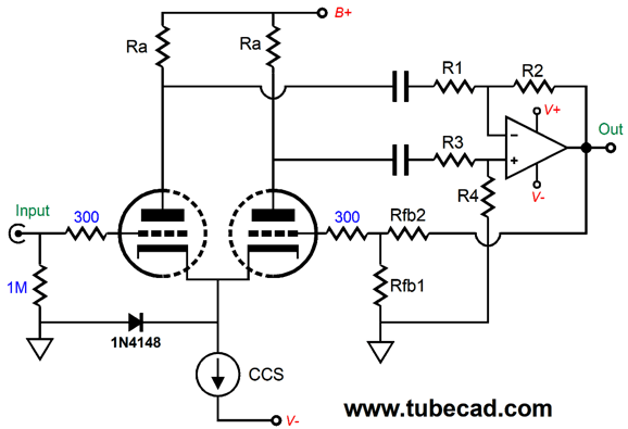
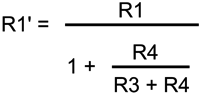
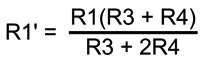
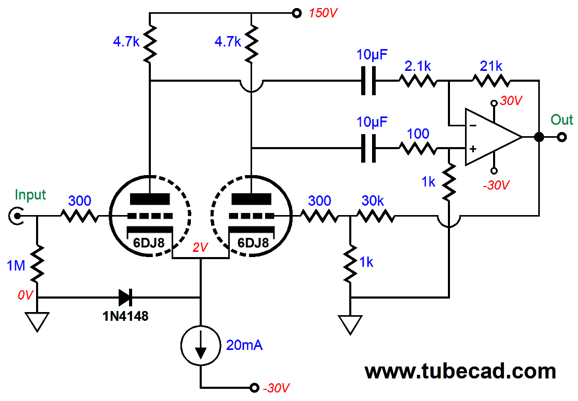
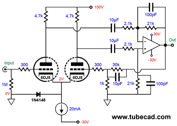
Well, I went digging through my notes and I found some interesting formulas I came up with for ensuring equal impedance loading from both of the solid-state power amplifier’s two inputs. Why would formulas be needed, when we can just use equal resistor values? Stop and think about it: the non-inverting input presents an input impedance equal to R3 + R4, while it’s inverting input presents an impedance lower than R1’s value. What? Once again, think about it: if the differential amplifier’s non-inverting input sees +1V, then the two-resistor voltage divider delivers +0.5V to the power amplifier’s non-inverting input, so its inverting input must match this +0.5V voltage, as that is the amplifier’s prime directive: both input voltages must match. Thus, the solid-state differential amplifier’s inverting input resistor, R1, sees a voltage differential of -1V to +0.5V, or a total of 1.5V, so resistor R1 will see a current flow threes bigger than resistors R3 & R4 see. In this example, we would need to triple resistor R1’s value to equalize the impedances. With different differential gain settings, we would need different resistor ratios. Here is where the formulas enter the picture. Where R1’ equals the effective impedance of R1. Since many believe that it is bad form to show a fraction within a denominator, here it is again. Now, if we want R1’ to equal the sum of R3 and R4, we must solve for R1’s value and up up with this formula. R1 = R3 + 2R4 I plugged this ratio into the following circuit and ran some SPICE simulations.
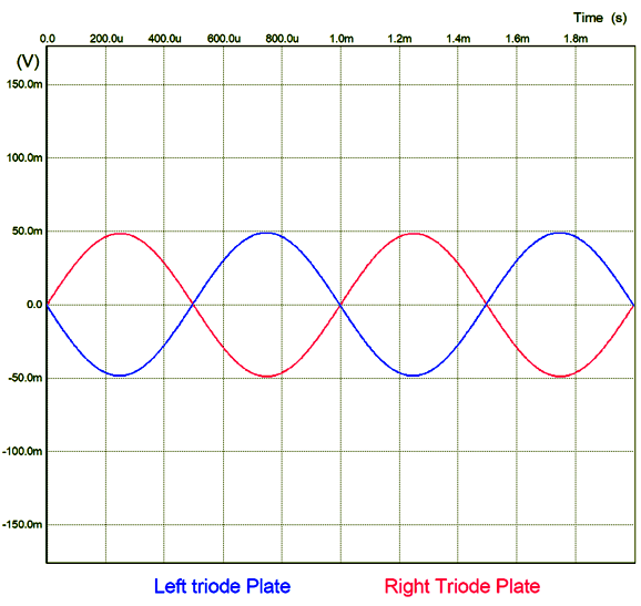
The 2.1k resistor, R1, effectively equals 1,100 ohms to AC signals. Sure enough, I got equal plate-voltage swings, which is only possible if both plates are equally loaded.
Well, how well did this circuit perform otherwise? Not as good as I expected and better than I expected. The PSRR came in at only -5.25dB and the THD was crazy low at 0.0017% at 20kHz. I had expected much better PSRR, but the distortion was amazingly low. I then undid the resistor ratio, so the two plates now saw different load impedances.
(Note that the frequency-compensation capacitors were also present in the previous version, but omitted from the schematic the sake of conceptual clarity. In addition, the solid-state amplifier used in SPICE simulations was not an LM3886, as I don't have its SPICE model, but an AD843 OpAmp and the load was 32 ohms, not 8 ohms. If you are guessing that I had long ago created the SPICE circuit, you are right.) The result was interesting. The PSRR vastly improved to -66dB and the THD rose just a wee bit to 0.099%. So, which arrangement is better? The only possible answer is the version with the dissimilar input impedances, as the thousand-fold improvement in PSRR far outweighs the slight increase in THD. Bear in mind, that these were SPICE simulations and that the improved THD would never be obtained in reality. Why not? In SPICE the power supplies are perfect, offering no resistance or inductance, cable of delivering a trillion amperes of current in a pico-second, while maintaining a regulation figure of 0.00000000000000001%. In SPICE, the triodes are perfectly matched, as are all the resistors and capacitors. Reality differs. In the real world, a THD meter cannot tell the difference between noise and distortion, so the poor PSRR would overwhelm the actual distortion and produce a reading of 1%, not 0.0017%. (In SPICE, we encounter another problem or, rather, difference from reality. SPICE Fourier analysis, which is what most used to determine THD, is sensitive to phase shift in the short term. For example, if we run a perfect 1kHz sinewave, but phase shifted by 45 degrees, for one cycle through the Fourier test, you will see a THD higher than 1%. Run it for three cycles and the apparent distortion decreases to about 0.1%. Run it for five cycles and the Fourier reading approaches the residual of SPICE's ability to resolve small numbers, about -200dB down, which is 0.00000001%. Real distortion analyzers might also give a falsely bad reading with only one cycle, but they seldom encounter just one cycle in actual testing, as 1,000 cycles of 1kHz occur in one second of real time.) Wait a minute, John, did you just made me go on that long trip and undergo needless math for nothing? Heavens no. Mistakes are the rungs of the ladder to success. If you are unwilling to make a mistake, then you are also unwilling to succeed. Besides, in another application, the equal input impedance version could yield real benefits.
What about frequency-compensation capacitors and this topology? The secret to differential amplifiers is equal capacitor loading on both inputs. For example, in the last schematic we see both the inverting and non-inverting inputs use the same-valued shunting capacitors. Actually, with the hybrid amplifier with cascading differential amplifiers, we can add three compensation capacitors.
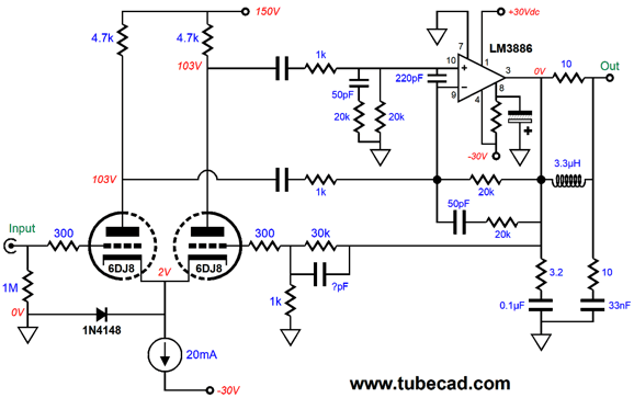
Of course, with a chip power amplifier, such as the LM3886, we will need many more parts to keep the solid-state amplifier happy.
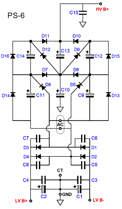
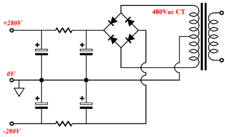
The above holds elements taken from the LM3886's data-sheet and Bob Cordell's book. Note that the tube-based input stage sets a fixed gain based on the feedback resistor values, but unlike solid-state OpAmps, the tube-based differential does not offer near infinite gain, so the actual total gain falls a tad short of what the feedback resistor ratio implies that the gain should be. The resistor that attaches to pin 8 should be about 47k, with 30V power-supply rails; the electrolytic capacitor can be any value from 10µF up. Also note that the two internal coupling capacitors hold no value in the schematic. Based on the low input impedance presented by the inverting input of the LM3886, you might assume that a huge-valued capacitor is needed. It's not. Bear in mind that the tube-based differential amplifier offers a high output resistance, roughly equal to the plate load resistor value, which is effectively in series with the feedback resistors. For example, in my SPICE simulations, I tried tiny 1µF capacitor values and the bandwidth extended below 10Hz. Thus, just to be safe, I would use 2µF to 10µF capacitors. Why did I choose +/-30V power-supply-rail voltages for the solid-state amplifier and 150V as the B+ voltage for the 6DJ8-based input stage? The voltages are arbitrary, but not the ratio of 1 to 5. When I see +/-30V power-supply-rail voltages, I instantly think and +150Vdc. Why? The GlassWare PS-6 power supply offers a 1-to-5 voltage quintupling ratio.
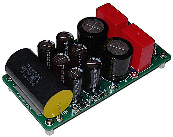
With this power supply board, you attach a 44Vac center-tapped transformer and you get +/-30V power-supply-rail voltages and +150V B+ voltage (actually, after the rectifier voltage drops, it's closer to 147Vdc).
Here is a link to the PS-6 User Guide (PDF), which is much better than my repeating what is inside it. (By the way, I only have few of these kits left and I plan on keeping at two for myself.) Let's now go on one of my famous side trips. When it comes to money in the bank, you can never have too much; just as Bill Gates or Warren Buffett. The same holds true for good looks, wit, charm, and intelligence. When doesn't more add more? I was about to add height to that list of personal attributes. But stop and think about it: while it is certainly better to be six-foot tall rather than five-foot tall, referring to men, not women. But would you really prefer being seven-foot tall over being six-foot tall? I wouldn't. What about eight-foot tall, any takers? Other than professional basketball players, I cannot imagine who would want to be that tall. (By the way, I always maintained that basketball should hold the rule that opposing tem's hoop should be four feet higher up than your tallest team member's height; right now, it's ten feet up. I am sure that is this rule were implemented, we would see many more six-foot tall pro basketball players and far more interesting games. You just got one of my famous side trips within one of a my famous side trips.) Now, let's think about audio amplifiers. Do you really want an 800W power amplifier? That would mean 113Vpk voltage swings into 8-ohm speakers. Enough voltage to easily kill someone attaching the speaker cable while the amplifier blared away. I know of one audio designer who developed a sweet-sounding 30W tube amplifier. Sadly, the owner of the company thought 30W too puny and insisted that the amplifier put out at least 40W instead. It took a lot of work, but the wattage was increased to 40W. How did the amplifier sound now? Much worse, embarrassingly so. Gone was the sonic glory and charm. Did that matter to the owner? No. Watts are watts, the more the better; period. He was lucky that I wasn't handed the assignment, as I would have triode-connected the output pentodes, thereby halving the wattage down to 15W—but what a sweet 15W they would have been.
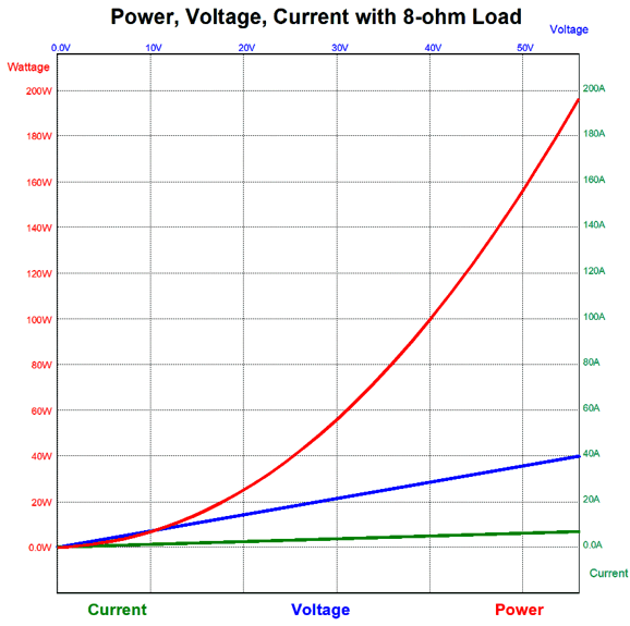
Let's switch to a sports car analogy. Imagine a fine, two-seater, sports car that accelerated and handled beautifully. The CEO of the car's maker, however, discovers late in the game that the car's top speed is 100MPH, which he believes will disappoint too many, as its speedometer reads up to 120MPH. Thus, the CEO declares that the car must be able to do 120MPH. The auto engineers plead to leave the car as it is, as it is already in production and close to perfection as it is, but they do not have the final word. So, as the design already held a fifth gear, larger tires are added and the rear axle differential gear ratio is reduced. The car now hits 120MPH, but it no longer accelerates or handles as well as it had before. The CEO is pleased; his customers, not so much. Returning to the 40W amplifier, I doubt that I can reliably hear the difference between 30W and 40W, for—as far as my ears and your ears are concerned—the difference is trifling. We should never have rated amplifiers in watts in the first place; using peak output volts or amperes would have made far more sense. My vote would go to current output, as it is the most sober of the three and it most closely tracks what the ear hears. A 40W amplifier does not sound twice as powerful as a 20W amplifier.
In short, with +/-30Vdc power-supply rails, we should easily be able to get 32W of output. Plenty.
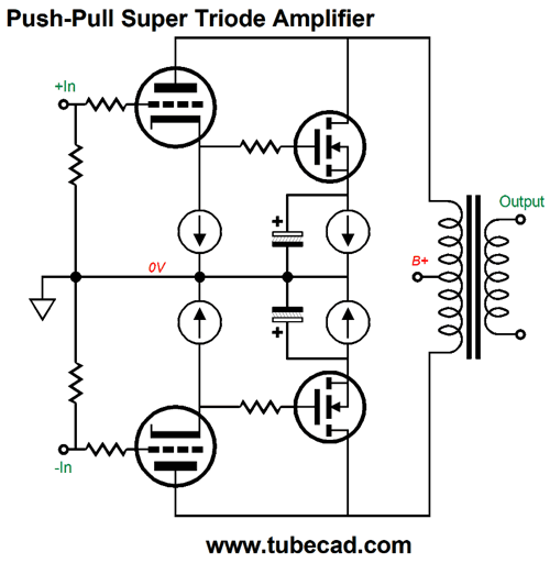
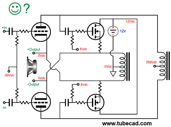
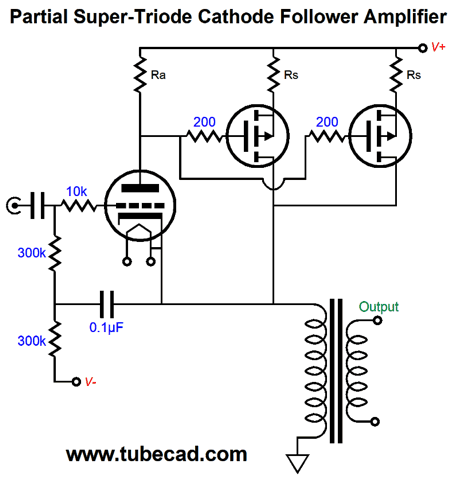
Push-pull Super-Triode Ideas
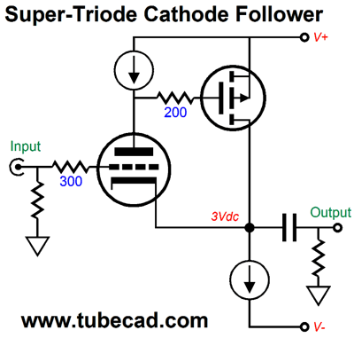
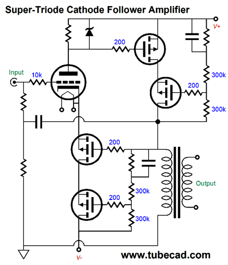
The two triodes operate in pure super-triode fashion, as neither drives the external load, and both run in strict constant-current mode (note the constant-current source at their cathodes), and, most importantly, both control their assigned power MOSFET and thereby impart their sonic signature over that of the MOSFETs. If we define work as the imparting of power into the loudspeaker, then the two triodes do no work. If we, on the other hand, define work as the job of making the amplifier sound like a tube-based one and not a solid-state effort, then the two triodes do most of the work. The MOSFETs receive their input signals from the two cathodes. If one triode sees a positive input signal at its grid, its cathode voltage will climb, prompting the partnered MOSFET to fire up its conduction, which will pull down the triode’s plate voltage—down to the point where the triode experiences no increase in current flow in spite of the positive grid voltage. Conversely, if one triode sees a negative input signal at its grid, its cathode voltage will fall slightly, discouraging the partnered MOSFET’s current conduction, which will force up the triode’s plate voltage—up to the voltage where the triode experiences no decrease in current flow in spite of the negative grid voltage. Get it? That was the super-triode concept in a nutshell. Two large-valued electrolytic capacitors shunt the two MOSFET source to ground, so that the MOSFETs amplify only AC signals. Note that both MOSFETs are auto-biased by the constant-current sources at their sources. Ideally, matched triodes would be used, but no matching is perfect or lasts forever. Thus, the four constant-current sources ensure that the triodes and MOSFET all get their exact share of current.
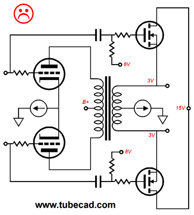
Note that one huge advantage that this push-pull arrangement holds over the single-ended equivalent is that the triode’s idle current does not drag down the output transformer, which is the case in the single-ended equivalent circuit. Single-ended output transformers hold an air-gap in their iron core that allows the output transformer to sustain steady DC current flow through the primary without saturating the core. Each single-ended output transformer offers a finite, all too finite, DC current limit. Unfortunately, the triode’s current conduction appropriates, pilfers, steals potential output power from the output transformer. For example, if a single-ended output transformer were rated for 200mA of idle current and the triode in a super-triode amplifier idled at 100mA, while the MOSFET drew 100mA, then the only one fourth of the power will be delivered to the loudspeaker that the output transformer could otherwise put out. In other words, it behooves us to give the MOSFET the lion share of current flow. In contrast, the push-pull output transformer in this super-triode amplifier will get a bit hotter due to the two triodes drawing constant current through the primary, but the core will not know that the triode are there, as it sees no net DC unidirectional current flow from either the triode’s or the MOSFET's conduction. Okay, now let's move on to other possible arrangements. I had the following idea decades ago. At first, I thought it would work well. After a few minutes of consideration, I changed my mind. It seemed obvious to me that the MOSFETs would completely overwhelm the triodes, in spite of the output transformer's winding ratio, as the triodes offer 1/100th (or less) of the transconductance of the MOSFETs. Then when thinking about super-triode circuits, this design came up again. Well, what if the winding ratio matched the the triode's amplification factor (mu), I wondered. But no, we still face the problem of the triodes losing tot he MOSFETs.
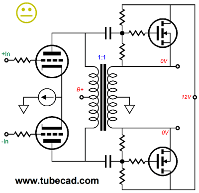
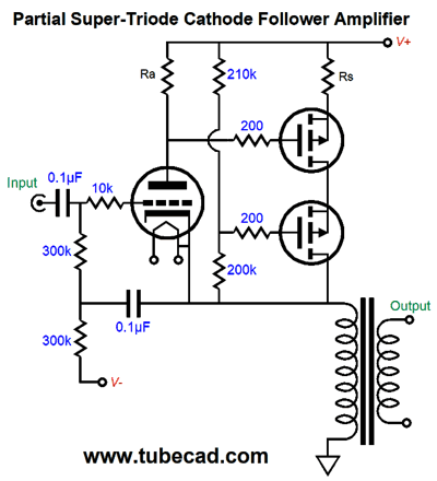
The problem was that the triodes are not controlling the MOSFETs and the triodes are actually trying to drive the external load. My view was that an isolation transformer could be used, i.e. one with a 1:1 winding ratio. This would allow the triodes to feed the MOSFETs their input signal, as shown below.
Although I am sure that this is a move in the right direction, I still fear that the triodes will not run under ideal super-triode conditions. Then it hit me: stop using an output transformer; use two center-tapped chokes instead.
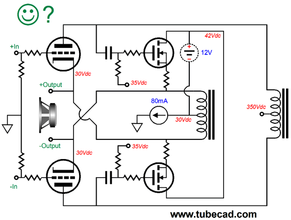
I love the look of the design and I bet that it either bombs or soars. Note that triodes control the MOSFETs and the center-tapped inductor loading of their plates means that that cannot deliver any real power into the speaker. At the same time, the triodes know instantly what the MOSFETs are up to, as the speaker attaches to their cathodes. Note how the 80mA constant-current source only feeds the two triodes, while the the two MOSFETs idle at their own separate idle current, which should be set to half the peak output current swing into the speaker , about 1.3A to 1.5A—thus, the low 12V floating power supply. Do not let the 12V fool you, as you could get +/-20Vpk voltage swings from the 12V power supply into the speaker, which would equal 25W, class-A watts, into 8-ohm loads. Use a 24V power supply and use multiple power MOSFETs in parallel and you can get +/-40V voltage swings, which would equal 100W into 8-ohm loads. Bear in mind that the center-tapped inductor can only do its magic in strict class-A operation. No free lunches. Also note that neither inductor requires an air-gap, as neither sustains a net unidirectional DC current flow. In other words, since the same DC current flow through both legs of the inductor, effectively in opposite directions, no magnetizing of the core occurs. Do note that the outputs are floating 30V above ground potential. Is this a problem? Usually no, but I am sure that Underwriter's Laboratory would not approve. One workaround is to use fixed bias on the triodes.
The above schematic shows zero volts at the outputs, which is not likely in reality, as the heavy current flow from the MOSFETs against the center-tapped choke's wire resistance will force some small positive DC offset voltage. In other words, we cannot use this voltage drop to accurately gauge the triodes' idle current. We could, however switch in series with the cathode an ammeter or we could read the voltage drops at center-tapped choke that the B+ voltage attaches to, which would be fairly large, in spite of the relatively light idle current flow from the triodes, as this choke must offer substantially greater inductance than the choke that attaches to the MOSFETs. In other words, high inductance means many turns of wire, thin wire, which means much higher DCR.
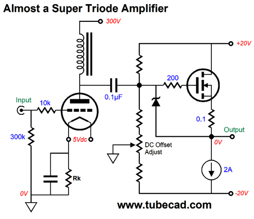
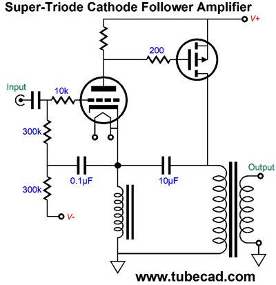
Single-ended Super-Triode Ideas (We have to careful with averages. The average person might be 38 years old, as far as the Earth is concerned, but less than 20 in Afghanistan and over 50 in Monaco. Recently, I heard on the radio that cricket was the world’s second most popular sport, and that it might soon become the world’s most popular sport. “How can that be? Who the hell cares about cricket?” I thought. Well, most of the men living in Afghanistan, Australia, Bangladesh, India, Ireland, New Zealand, Pakistan, South Africa, Sri Lanka, United Arab Emirates, West Indies islands, much of Africa and chunks of Canada and this wee country called Great Britain care a bunch about cricket. Basically, anything that is popular in either India or China is, by virtue of that fact alone, popular in the world.) Let's warm up with an amplifier that almost achieves super-triode status.
The triode does not deliver any power into the speaker, only the MOSFET and constant-current source do, just as a super-triode design must. The triode operates under constant current, because of the inductor loading at its plate, just as a super-triode design must. This amplifier fails at the third criteria of super-triode, however, as the triode must control what the solid-state device does to the output signal. In this example, the triode has no idea what the MOSFET did to the audio signal that the triode passed to it. By the way, do not fret about the zener diode; it is only there as a safety device, should the speaker cables get twisted and short the amplifier's output to ground, as the zener will prevent the MOSFET from trying to deliver 100A of current into the short. Another by the way, we can add an auto-bias feature, as this output stage runs in strict class-A.
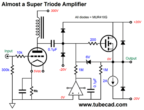
The DC servo ensures that no DC offset appears at the output. What are all those other diodes doing there? More safety features. Here is me quoting myself from post 212:
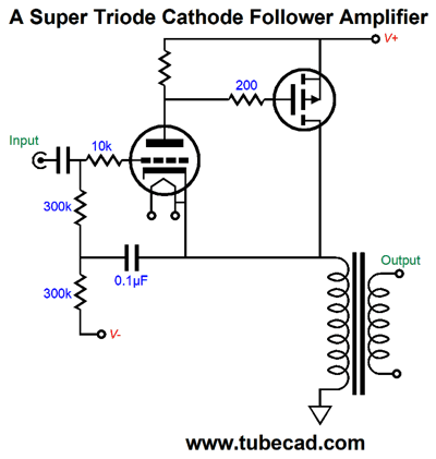
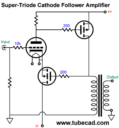
The diodes at the output protect against any inductive kickbacks from the speaker. The diodes at the MOSFET's gate protect the MOSFET, should someone jiggle the triode in its socket, cause the plate to lose contact with the inductor, thereby causing the MOSFET's gate to see a horrendously huge voltage spike. The following design gets close enough to the super-triode ideal that we might as well considerate having arrived. (If we replaced the plate resistor with a constant-current source, we would be 100% there.) This is a cathode-follower output stage, which offers no signal gain, but does offer low distortion and fantastically low output impedance.
If the cathode does not follow the grid exactly, the MOSFET will alter its current flow to force the primary inline. Because the MOSFET's transconductance is so huge, the triode will only slightly change its conduction to bring about a big change in the MOSFET's conduction.
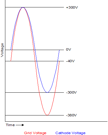
The triode's grid will, however, have to see huge input voltage swings to bring the output to full power. See post 230 for more information on cathode-follower output stages.
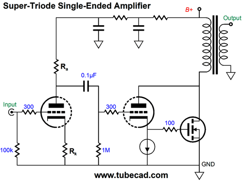
As you can see from the above graph the grid must experience a bigger voltage swing than the cathode undergoes. This explains why the 0.1µF capacitor is there. It bootstraps the grid resistor so as not to drag down the signal source. As mentioned in the above section devoted to push-pull super-triode designs, the single-ended super-triode suffers from the triode's current not only being wasted, but its current actually subtracting from potential wattage into the speaker. Think about it: the triode is effectively just a large and expensive constant-current source, as far as the output transformer is concerned.
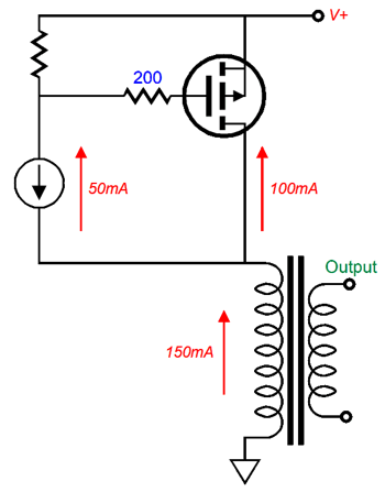
One workaround is to back away for pure super-triode operation and let the triode do some of the hard work of driving the speaker. All we have to do is use a source resistor with the P-channel MOSFET. The bigger this resistor is in value, the more work that will be passed on to the triode. Indeed, we can play with the math until we find the right plate and source resistor values needed to bring about parity between triode and MOSFET.
One advantage of using a source resistor, even a small-valued one, say 0.1-ohms, is that it allows us to parallel up several power MOSFETs, as the source resistors limit current hogging.
Now, we can run an equal three-way current division between the triode and two MOSFETs. Still, I would prefer to cascode the MOSFET, as I fear an over voltage taking out the MOSFETs. Once again, an inductive device, i.e. the output transformer, in the circuit can cause unexpectedly high-voltage swings should something go wrong, such as the speaker becoming disconnected during a loud passage. Vacuum tubes are amazingly robust in this regard; solid-state devices, not so much.
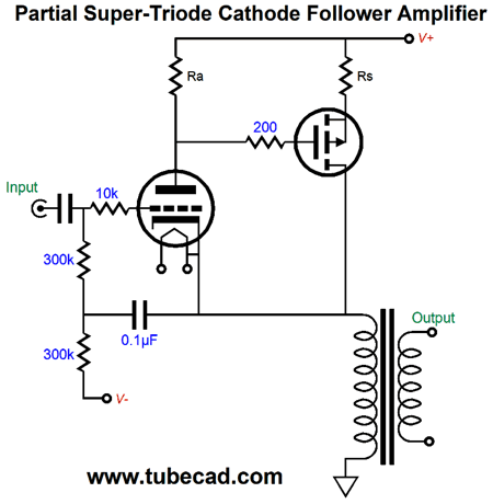
By placing the two MOSFETs in series we have effectively doubled the source-to-drain breakdown voltage. If you are thinking that you can use an expensive lateral MOSFET at the top and a cheap IRF MOSFET at the bottom, you probably would be disappointed, as the lateral MOSFETs offer a much lower turn-on voltage, which in general is great, but in this circuit it makes for a smaller-valued plate resistor, Ra. Why is that a problem? The bigger that Ra is in value, the greater the control the triode has over the MOSFETs. Returning to purer super-triode ideas, the following design separates the triode's DC current path from the MOSFET's, so the output transformer is no longer dragged down by the triode's constant-current flow.
The 10µF capacitor AC couples the cathode to the output transformer's primary; thus, the triode does know what the MOSFET is doing to the AC signal. So far, everything is good. What is not good, however, is that setting the P-channel MOSFET's idle current will be next to impossible without a DC servo that monitors the DC voltage drop across the primary's DCR (DC Resistance). We can eliminate the capacitor and inductor by adding a negative power-supply rail (whose voltage magnitude equals the B+ voltage) and another P-channel MOSFET.
The the primary's DCR effectively becomes a cathode resistor with which to cathode-bias the triode. For example, if the DCR is 200 ohms and the idle current through it is 150mA, then the voltage drop across the primary will be 30V. We then add about 4.5V to the 30V to get the triode's cathode voltage, or 34.5V, which is close to what a 2A3 would need to idle at 50mA with about 250V on its plate. We can place two MOSFETs in series in both positions.
(Yes, a few extra bells and whistles got thrown in the mix. The capacitor-shunted resistors should see a voltage drop equal to twice the MOSFET's turn-on voltage. The zener limits the maximum current flow from the topmost MOSFET. The capacitor at the bottom of the triode's grid resistor bootstraps the input resistance, so the signal source is not dragged down trying to deliver huge voltage swings into the resistance.) The imporant feature here is that the triode's near constant-current flow never enters the primary, so the output transformer is not burdened. Making a high-voltage bipolar power supply is no big deal, as center-tapped tube power transformer can be used.
The triode will need a floating heater/filament power supply that is referenced to its cathode, as the cathode will undergo huge voltage swings far above ground level and far below.
Your Homework Assignment You will need this background information for my next post, which will explain how many modern tube-amplifier manufactures have goofed their way to success.
//JRB
Next Time
User Guides for GlassWare Software
For those of you who still have old computers running Windows XP (32-bit) or any other Windows 32-bit OS, I have setup the download availability of my old old standards: Tube CAD, SE Amp CAD, and Audio Gadgets. The downloads are at the GlassWare-Yahoo store and the price is only $9.95 for each program. http://glass-ware.stores.yahoo.net/adsoffromgla.html So many have asked that I had to do it. WARNING: THESE THREE PROGRAMS WILL NOT RUN UNDER VISTA 64-Bit or WINDOWS 7 & 8 or any other 64-bit OS. I do plan on remaking all of these programs into 64-bit versions, but it will be a huge ordeal, as programming requires vast chunks of noise-free time, something very rare with children running about. Ideally, I would love to come out with versions that run on iPads and Android-OS tablets.
//JRB
|
|
Kit User Guide PDFs
Only $12.95 TCJ My-Stock DB
Version 2 Improvements *User definable Download for www.glass-ware.com |
||


| www.tubecad.com Copyright © 1999-2017 GlassWare All Rights Reserved |