| John Broskie's Guide to Tube Circuit Analysis & Design |
17 July 2016 Post 388
Special Thanks My second goal is to gather 1,000 patrons. I have 959 patrons to go. If you enjoyed reading this post from me for the last 18 years, then you might consider becoming one of my patrons at Patreon.com. It would make a big difference to me. Thanks.
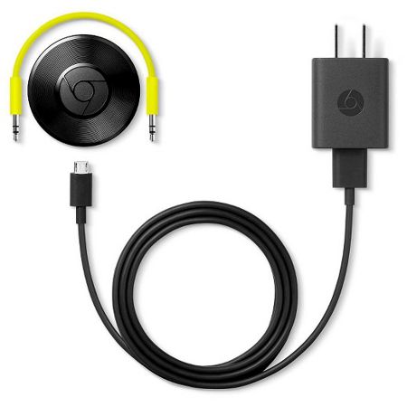
Chromecast Audio Update
One fear remained, however. I wondered about how two coupling capacitors, even electrolytic coupling capacitors, could be fitted within so small an enclosure. One workaround employed in other small audio devices, such as phones and MP3 players that must drive 16-ohm headphones, is to forgo the output coupling capacitors and let the 2.5V DC offset emerge through a clever setup. In other words, let's say that you have only +5V to work within and that you do not want to use coupling capacitors; well, the sneaky solution is to use three output amplifiers, not two.
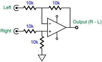
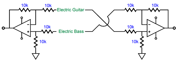
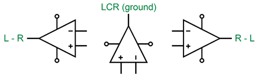
I know that many are thinking that I am going to describe a rail splitter circuit that halves the +5V at its output, creating a virtual ground at +2.5V; I am not. Instead, what I am going to describe will at first baffle and then astonish your mind by it outside-the-box thinking—well, at least it did to me, the first time I encountered it. Each of the three amplifiers gets its own separate audio signal. The amplifier that feeds the right headphone driver receives a blend of the right-channel signal minus the left-channel signal, while the amplifier that drives the left headphone puts out a blend of left-channel signal minus right-channel signal. What!? Yes, it is easy to perform the algebraic function of R–L by using the following circuit.
This is the classic differential amplifier configuration. If both of the amplifier's inputs see the same signal, nothing appears at the amplifier's output. If the signal is presented to the inverting input, it appears with the same magnitude—but phase inverted—at the output; if presented to the non-inverting input, then it emerges in phase and equal in amplitude. What becomes interesting is when we apply signals to both inputs at the same time. Now, there are those who think primarily in a symbolic fashion, either mathematically or logically; they are rare and I love them. Most, on the other hand, hate the smallest whiff of Greek letters, as I have discovered. So, let's use three musicians instead: a lead guitarist on the left, a drummer in the center, and a bass player on the right (with a singer in the center, but who is sitting this instrumental piece out).
If we send the lead guitarist's electric guitar output to the differential amplifier's inverting input and the bass player's electric bass output to the non-inverting input, we get a mix of both signals, with the bass guitar emerging in phase, but the lead guitar signals are inverted. Now, we do the same thing, but inverted. We feed another differential amplifier the same guitar and bass signals, but this time the bass player's signals are inverted, while the lead guitarist's signals are in phase. We then send the two outputs to the headphones' two drivers.
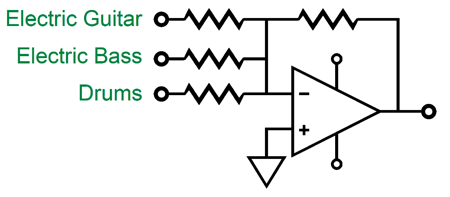
What about the drummer's efforts? The microphone in front of the drum kit feeds the third amplifier. Did you forget the third amplifier? We can't, as it plays a crucial role in this arrangement. It receives not only the drums, but the guitar and bass signals as well, and in inverted phase. Mono, in other words. The third amplifier puts out the sum of all three musicians efforts and its output becomes the effective “ground,” in this setup.
Okay, this gets weird, so brace yourself. The headphone driver is a small, single loudspeaker, a small diaphragm and coil of wire that is immersed in a strong magnetic field. The headphone driver is an intrinsically differential device, as it only responds to voltage differentials. Expose both of the driver's terminals to +1V or to +10V or +100V and nothing happens; no differential voltage, no output. Well, if we feed the output of amplifier that holds the in-phase guitarist and inverted bass player signals to the left headphone driver's positive terminal and attach its negative terminal to the third amplifier's output, which holds inverted mono, you will hear only the guitar and drums, no bass guitar signal. None, zip, nada. Magic. Or, rather, simple algebra, as +guitar to –guitar equals +2guitar, which the headphone driver responds to eagerly. But the headphone driver cannot respond to the bass guitar signals, as –bass to –bass equals no difference, so no response from the driver. The drums signal is only present on the inverted third amplifier's output; thus, the left headphone driver sees a differential signal equal to just +drums, not +2drums. How is this possible? The left-channel amplifier acts as a virtual ground to the third amplifier's output, so it can sink the currents generated by the third amplifier's output that travel through the left headphone driver. Doesn't' the drums emerge phase inverted from the left headphone driver, as the third amplifier inverts it output signals? No. Remember that the left headphone driver's negative terminal is “grounded” into the third amplifier's output, so we get two inversions, which makes for no inversions, as inverted inversion equals no inversion. Note that the lead guitar signal became effectively twice as big, but the drum signal sees no doubling. Is this a problem? No. The right headphone driver will attach its negative terminal the third amplifier's output and its positive terminal to the right-channel amplifier whose output signal consists of inverted lead guitar and non-inverted bass guitar, with no drums. The right headphone driver then puts out sound made up of +2bass and +1drums. Your ear sums the common drum sounds to equal +2drums, which matches the +2guitar in the left ear and the +2bass in the right ear.
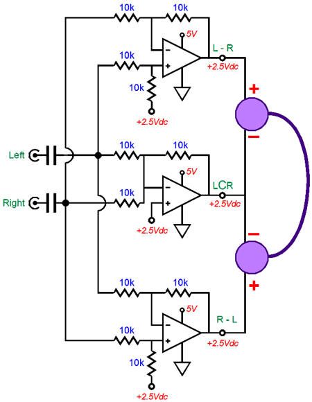
Okay, this elaborate system works, but what have we accomplished by it? No coupling capacitors. Since all three amplifiers present half of the single positive rail voltage (5V in this example) 2.5Vdc at their outputs, both headphone drivers do not “see” this huge Dc offset voltage; nor do they see a huge-valued coupling capacitors. Very clever, no? Mind you, the third amplifier that delivers the inverted mono signal must be able to deliver twice the current swings than the left and right amplifiers can deliver. Imagine that a mono signal source were being played; the left and right amplifiers would be putting out no signal, while the third amplifier would be putting out -2mono, which would flow into both headphone drivers. (In actual use, this third amplifier might actually consist of two amplifiers working in parallel, each with a small-valued resistor at its output.) Now, let's say that someone owns a mono ear-bud (or mono headphones) and that he plugs this into the MP3 players stereo headphone jack, what does he hear? Well, with only two amplifiers, he would only hear one channels signal. But with this elaborate L-R, -LCCR, R-L three amplifier solution, he would hear the mono combined sound of both channels, as the single ear-bud would be driven by the third amplifier and one other amplifier. But John, I don't own any three-channel recordings, only two-channel stereo recordings, so I cannot mix just left and right signals with a center-channel signal. Actually, both the left and right channels of a stereo recording holds the center channel signal, but at half volume. In other words, the left channel holds Left + Center/2, while the right channel holds Right + Center/2. If we combine the two signals we get Left + Center + Right. Here is the entire circuit.
Returning to my fear that that the Google Chromecast Audio puck might hold this arrangement, it doesn't'. If it did, would that be a problem? Yes, it would, as many of the circuits that I proposed in posts numbers 386 and 384 assumed that puck's power supply ground and the signal ground were one in the same. With the three-amplifier setup, that is not true, as the signal ground is actually a virtual ground that holds its own signal. I made a few quick measurements of the Chromecast Audio puck with a voltmeter and I could not measure any DC offset from the its power supply ground to the output signal ground; nor could I measure any AC signal from the signal ground relative to the power supply ground. Whew, that was a relief, but one small problem remained, which was that I couldn't see how they got away with no coupling capacitors and not using the three-amplifier solution; additionally, I could not see how they got such large output voltage swings from a 5V power-supply rail voltage. The only way out, as I saw it, was that the Chromecast Audio puck held a switched-capacitor, charge-pump negative-power-supply-rail-creating circuit. These circuits create a negative power-supply rail from a single positive power-supply rail. Well, after some searching on the web for answers, I discovered that the Chromecast Audio puck has been taken apart by ifixit.com. Their results were that the Chromecast Audio puck held a fairly-good DAC (AK4430) from AKM (Asahi Kasei Microdevices), whose DACs are highly esteemed by those in the know. I know their DACs and I like them a great deal.
In post 222, I quoted from a DAC layout PDF from AKM that held the following gem:
Here is the full Chromecast Audio part line up found at the ifixit website:
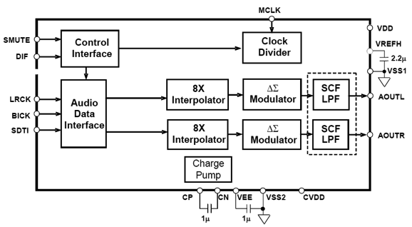
The last item is interesting, as it is seemingly not needed. The AKM DAC already holds a negative-power-supply-rail-generating circuit and offers voltage outputs, not current outputs, so the DRV632 dual-OpAmp driver IC is seemingly redundant. Here is the overview of the AK4430.
My guess is by itself the AKM4430 DAC couldn't offer the stellar specifications that Google required. Think about it, the Chromecast Audio puck's output signals might terminate into some tough loads, as some self-powered loudspeakers present brutally-low input impedances. The DRV632, in contrast, can deliver up to 25mA of peak current and can even drive 600-ohm loads, a task that the DAC could never accomplish.
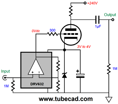
I actually have considered the DVR632 IC before for tube-audio use. The idea was simple: we start with a grounded-cathode amplifier stage, then we replace the cathode resistor with a zener diode that is bypassed by a large-valued capacitor; we then place the DRV IC in parallel with zener. The DRV IC will create its own negative power-supply rail voltage, so we do not have to provide one for it. Its output will be ground-referenced with no DC offset, so we can DC couple its output to the triode's grid.
That's great, John, but how does this improve upon just driving the grid directly? We can use the internal OpAmp to develop gain. Here is one possibility. The DVR632 develops a gain of 2, which the 6SN7 amplifies by a further tenfold, resulting in total gain of 20, easily enough to drive a 6BQ5/EL84 to full output with an input signal of only 1Vpk. Or we could configure the two OpAmps within the DRV632 as an unbalanced-to-balanced converter with a gain of 4 (+12dB differentially).
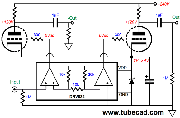
The two 6DJ8 triodes see equal anti-phase input signals and can easily drive two EL34 output tubes to full output in a push-pull power amplifier. (The feedback resistors are actual external to the DRV632 IC, not inside it as shown in my schematic.) Another line driver IC from Texas Instruments that I have had my eye on is the DRV134. Back in the days of trying to drive my Sennheiser HD580s from a 9V battery, so I could listen to music as I walked to work (in spite of loud road noise), I thought that differential output with 4.5V DC offset was the possibly the best solution. See post number 20.
The ground would be the nexus between two 10k resistors in series that spanned across the 9V battery terminals. The fixed gain of +6dB was just about perfect. I figured that one DRV134 per channel and two 9V batteries would fit in a small metal mint tin. (Actually, I was thinking that a vintage cigarette carrying case that I had seen in a pawnshop might be the better enclosure.)
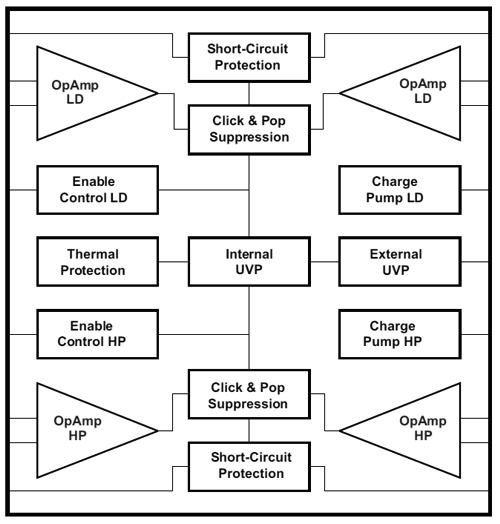
In short, the more I learn about the Chromecast Audio puck, the more impressed I am by it. Review that list of goodies inside the tiny puck. Truly impressive and no wonder that runs so hot. Perhaps, Google will one day come out with a premium Chromecast Audiophile puck, which will sport the AKM AK4497 DAC, the AKM current flagship 32-bit DAC. The puck would have to be almost twice as large and should offer three outputs: normal stereo out and two balanced outs. Indeed, this audiophile-grade puck could hold the DRV632's bigger brother, the DVR604, which holds two line drivers and two headphone amplifiers. (The much higher performance headphone amplifier from TI, the TPA6120A2, runs crazy hot and requires a negative power-supply rail.)
DRV604 System Block Diagram Indeed, I would use two DRV604s, so balanced outputs, both for line and headphone out, could be offered. Balanced out for the headphones would double the potential output swing into 32-ohm headphones and consequently quadruple the power into the headphones. A fair price for such a premium Chromecast Audiophile puck would be $100, not $99. I truly like the $35 price-tag for the current non-premium Chromecast Audio puck, much better than $34.99, which not only is cumbersome, but actually seems higher in cost. (Google have your people call my people and I will be glad to give you a bunch more free advice.) Given that the Chromecast Audio puck already holds a fairly robust line driver IC, I can easily imagine that Google would update their software so that one puck could be used for each channel with a balanced set of outputs, which could even drive 600-ohm loads. The two required pucks would then be made joined in a Chromecast Audio group, so normal stereo playback would be possible.
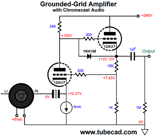
When I was brainstorming possible tube circuit topologies for use with the Google Chromecast Audio puck, I left out grounded-grid designs, as I feared that the puck would not be able to drive the intrinsically low input impedance presented by the cathode.
I needn't have worried, as the DVR can easily drive the 2,950-ohm input impedance of the following circuit. Normally, the cathode's output impedance is equal to (rp + Ra)/(mu + 1), but with the negative-feedback loop in place, the math get trickier and the cathode's impedance goes up, not down.
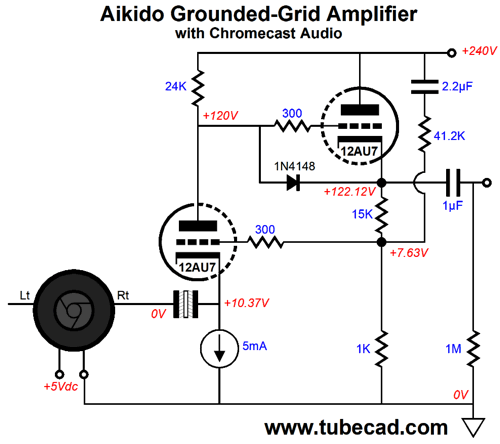
The input 12AU7 triode is configured as a grounded-cathode amplifier with its input signal taken at its cathode. The constant-current source loading its cathode auto-biases the input triode and helps to increase the input impedance, whereas a cathode resistor would drag down the input impedance. The non-polarized electrolytic coupling capacitor bridges the Chromecast Audio puck's output to the input triode's cathode. Since the grounded-grid amplifier does not invert its input signal's phase at its output, we can use the grid as an inverting input for negative feedback, as shown above. We can also apply some Aikido mojo to improve the topology's PSRR.
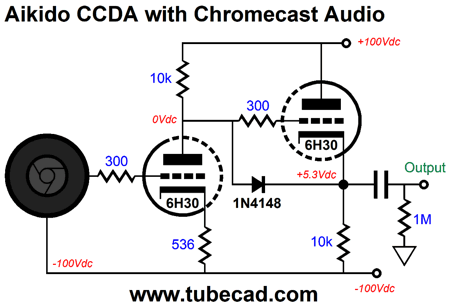
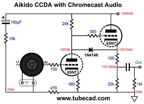
We have purposely injected a portion of the power-supply noise to the input triode's grid so that the power-supply noise can be nulled at amplifier's output. A while back, I showed an Aikido CCDA for the Chromecast Audio puck back in post 384.
This design relied on a bipolar power supply and referencing the puck down at the negative power-supply rail. Well, we can use a monopolar power supply and still apply some Aikido mojo to the CDDA circuit.
I showed how a floating signal source, such as a phono cartridge, could be used with a two-resistor voltage divider to impart some Aikido mojo into a grounded-cathode amplifier before. See post number 327, which offered the following example.
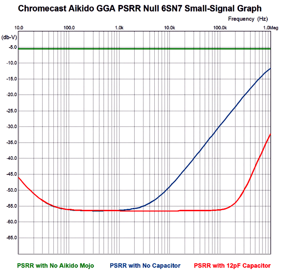
Well, the Chromecast Audio puck is free-floating, so it can be used in this topology. As I looked at the penultimate circuit, I realized that the 470-ohm resistor was effectively in series with the 100-ohm grid stopper resistor. Thus, I wondered if Miller-effect capacitance would be an issue. In addition, I worried about the huge 150µF capacitor presenting too high an ESL (effective series inductance). This made me wonder about shunting the capacitor and 10k resistor with a small-valued capacitor. Interesting results. Here is a SPICE-generated graph.
The green plotline shows a stock CCDA's PSRR. The Blue line reveals the basic Aikido mojo and the red line shows what adding the 12pF capacitor produces. Actually, the most important frequency to look at is twice your wall-voltage frequency, as that is where the rectifier-induced ripple resides, 100Hz in Europe and 120Hz here in the States. Ideally, the CCDA stage will not produce any audio-signal-induced aberrations in the B+ voltage and the RC filter capacitors should provide a low impedance at high frequencies. Nonetheless, that red plotline looks impressive. I would love to build this circuit just so I could try it with and without the added 12pF capacitor. Actually, I would build the following version.
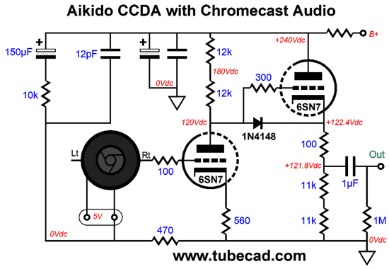
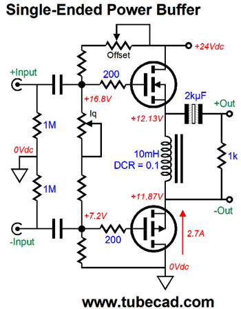
Effectively, two 12k resistors in series are the same as one 24k resistor, but I like the idea of the two plate resistors seeing less voltage differential. Mind you, the Chromecast Audio puck already produces a hot output signal. But for those who need more gain, the above circuit would work well. Imagine it as the frontend of an EL84-based single-ended power amplifier. Speaking of single-ended power amplifiers...
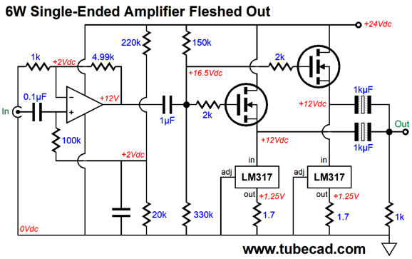
A 6W Single-Ended Power Amplifier
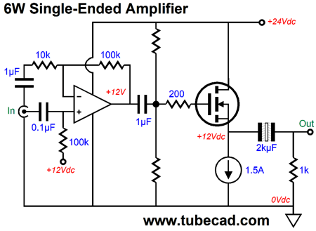
Since the constant-current source already automatically sets the idle current, we can use fixed bias to center the output stage, leaving the task of signal gain to an OpAmp. The obvious setup, the one where the OpAmp DC couples to the MOSFET output stage and applies a global negative feedback loop to the amplifier's output, is obvious and will not be considered here. Instead, we will look into not using a global feedback loop and not DC coupling the OpAmp to the MOSFETs. Why? With a 6W amplifier, even with horn loudspeakers, we must expect clipping. My hunch is that a global negative feedback loop will only marginally lower distortion and output impedance, but will significantly worsen clipping behavior. I am convinced that one reason that tube amplifiers are so well liked is that they do not clip hard, nothing like the sharp, harsh clipping from solid-state amplifiers with high feedback ratios.
DC coupling would ensure output stage centering and offer lower-frequency bandwidth, but less output power. Why less power? The MOSFETs require big turn-on voltages at their gates, say about 4V to 5V, which the OpAmp cannot provide at full output, as its output voltage swings are too limited by the tiny power-supply rail voltage. By using a coupling capacitor between OpAmp and MOSFETs, however, we can get an effectively bigger output swing from the OpAmp, which will result in more output power to the loudspeaker. As I look at this schematic, I fear heat. To get 6W, an 8-ohm speaker needs to see 10Vpk voltage swings and 1.25Apk current swings. We set the constant-current source to 1.5A to buy us some extra juice, should the speaker's impedance dip a bit below 8 ohms. Well, 1.5A against 24V equals 36W of heat at idle, with both the MOSFET and constant-current source dissipating 18W. Heat, lots of it, even with the wimpy 6W of output. We cannot dissipate any less heat in a class-A, single-ended amplifier, but we can distribute the heat across more devices.
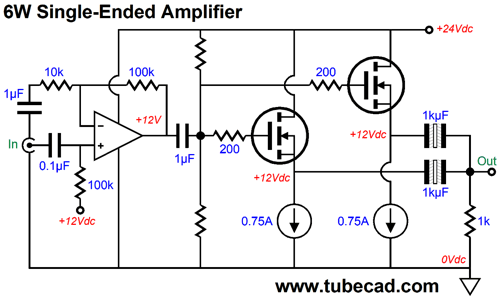
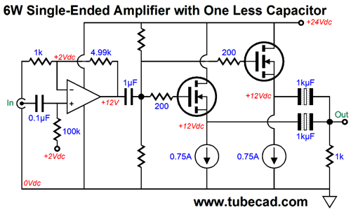
Two MOSFETs and two constant-current sources are used to distribute the heat across more devices and to allow the use of LM317 voltage regulators as constant-current sources. In addition, the two constant-current source and two coupling capacitors mean that we do not have to use matched MOSFETs. Note that both of the OpAmp's inputs center at 12Vdc, while the 1µF capacitor terminating the feedback resistor string retains all of the OpAmp's DC gain. The thing is the OpAmp is capacitor coupled to the MOSFETs and the MOSFETs are capacitor coupled to the speaker. This means that we can lose the 1µF capacitor terminating the feedback resistor string, as the following schematic shows.
Note that both of the OpAmp's inputs now center at 2Vdc, not 12Vdc. In other words, the amplifier's feedback resistors set a gain equal to 6, which against the 2V reference voltage equals 12V at the OpAmp's output. This means that 1.67V of peak input signal will be needed to drive the amplifier to full output, i.e. 10Vpk and 6.25W. (If we set the gain to 10, then the 2V reference voltage would have to be lowered to 1.2V, which might prove too low for many OpAmps; one exception being the AD823, due to its FET input stage.) Okay, let's flesh out this design.
The LM317-based constant-current sources use 1.7-ohm current sense resistors, which as far as I know are not made. The easy workaround is to place three 5.1-ohm resistors, which are made, in parallel. Each MOSFET and LM317 dissipates 9W at idle, which isn't too bad and would even allow for PCBs-mounted heatsinks to be used. For example, the 2.5in tall heatsink that comes with my kits offers a low 2.6C/W thermal resistance, which means that 9W of dissipation would cause the heatsink's temperature to rise by 23.4 degrees C. (If the device dissipates 1W, then its temperature rises by 2.6C.) Assuming an ambient temperature of 25C, results in a heatsink temperature of only 48.4C (118.4F), hot but not burning hot. More importantly, the LM317's junction temperature climbs to only 93.5C. Actually, the more I look at the above schematic, the more I like the idea of giving each MOSFET two LM317-based constant-current sources. Why? Because the LM317 is the weakest link here, in thermal terms. (Do not try another adjustable positive regulator in its place, such as the LT1083; I have and the results were not good. In short, the LM317 makes a surprisingly good constant-current source.)
If anyone at Texas Instruments is reading this (I know that I used to readers at National Semi), then put in the suggestion box the idea of packing the LM317 (and LM337) in the TO-247 package, as the junction-to-case thermal resistance is about three times lower than that of the TO-220 package. Who would want a 6W, solid-state, single-ended amplifier? I would. I have been thinking of building a tube-based power amplifier for my computer loudspeakers, which actually sound quite good, as they are dipole planar types with a 6in subwoofer.
One problem with using a tube amplifier is that the computer is on 16 hours a day. Do I really want to burn the tubes for the same amount of time? In contrast, solid-state devices, even those that smolder in a class-A amplifier will certainly outlast me. In addition, I own several high-current 24Vdc switcher table-top power supplies; they languish in a box. By the way, did you see the two letters, S & E, at the top of this section? Or, did you see four red shapes that look like pieces from a jigsaw puzzle? //JRB
User Guides for GlassWare Software Since I am still getting e-mail asking how to buy these GlassWare software programs:
For those of you who still have old computers running Windows XP (32-bit) or any other Windows 32-bit OS, I have setup the download availability of my old old standards: Tube CAD, SE Amp CAD, and Audio Gadgets. The downloads are at the GlassWare-Yahoo store and the price is only $9.95 for each program. http://glass-ware.stores.yahoo.net/adsoffromgla.html So many have asked that I had to do it. WARNING: THESE THREE PROGRAMS WILL NOT RUN UNDER VISTA 64-Bit or WINDOWS 7 & 8 or any other 64-bit OS. One day, I do plan on remaking all of these programs into 64-bit versions, but it will be a huge ordeal, as programming requires vast chunks of noise-free time, something very rare with children running about. Ideally, I would love to come out with versions that run on iPads and Android-OS tablets.
//JRB |
Kit User Guide PDFs
And
High-quality, double-sided, extra thick, 2-oz traces, plated-through holes, dual sets of resistor pads and pads for two coupling capacitors. Stereo and mono, octal and 9-pin printed circuit boards available.
Designed by John Broskie & Made in USA Aikido PCBs for as little as $24 http://glass-ware.stores.yahoo.net/
The Tube CAD Journal's first companion program, TCJ Filter Design lets you design a filter or crossover (passive, OpAmp or tube) without having to check out thick textbooks from the library and without having to breakout the scientific calculator. This program's goal is to provide a quick and easy display not only of the frequency response, but also of the resistor and capacitor values for a passive and active filters and crossovers. TCJ Filter Design is easy to use, but not lightweight, holding over 60 different filter topologies and up to four filter alignments: While the program's main concern is active filters, solid-state and tube, it also does passive filters. In fact, it can be used to calculate passive crossovers for use with speakers by entering 8 ohms as the terminating resistance. Click on the image below to see the full screen capture.
Tube crossovers are a major part of this program; both buffered and un-buffered tube based filters along with mono-polar and bipolar power supply topologies are covered. Available on a CD-ROM and a downloadable version (4 Megabytes). |
||


 .
. 


| www.tubecad.com Copyright © 1999-2017 GlassWare All Rights Reserved |