| John Broskie's Guide to Tube Circuit Analysis & Design |
26 September 2016 Post 397
Special Thanks to the Special 54
If you have never produced a technical white paper or written an article on electronics, you probably cannot imagine how much time and effort is required to produce one of my posts. My lifetime goal is reaching post number one thousand. I have 603 more to go. And with only three more to go, I should easily be able to hit post 400 this year. Four hundred posts! The mind boggles. How many words will that be? How many schematics drawn? How many graphs shown? I do not want to know. My second goal is to gather 1,000 patrons. I have 944 patrons to go. If you enjoyed reading this post from me for the last 18 years, then you might consider becoming one of my patrons at Patreon.com. It would make a big difference to me. Thanks.
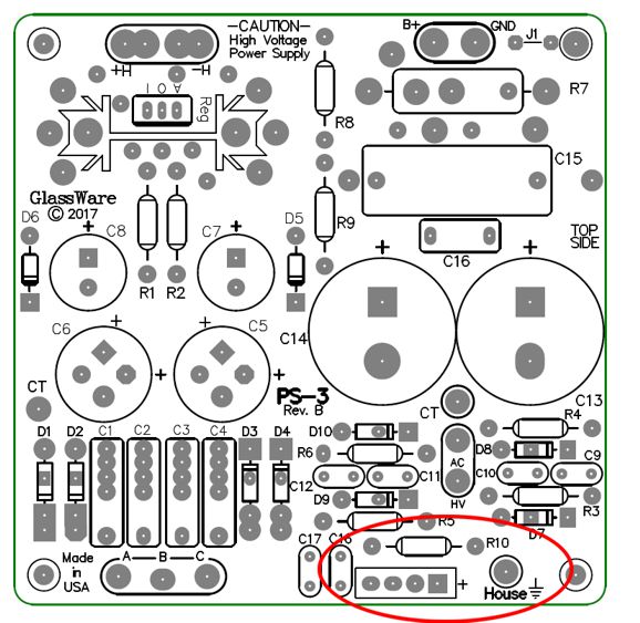
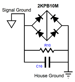
The house-ground circuit is simple enough; it uses a bridge rectifier and parallel resistor and capacitor to attach to the house ground, i.e. the third jack on a wall socket. The wall outlet's third jack connects to the house ground, which is also known as "earth," as the house ground is often created by attaching the wall socket's neutral connection to an 8-foot metal rod buried in the dirt under your house or to the cold-water pipe, assuming that the pipe is made of metal. This is an important safety feature. let's say that something goes terribly wrong in your power amplifier and the hot/live AC wire connects to the chassis, creating a dangerous situation, as you could receive a lethal shock from touching the energized chassis. But with a solid connection made to the house ground, the hot AC voltage would drain away safely. Unfortunately, a direct connection the house ground of the chassis and signal ground often causes hum problems, as other electric items are also attached to the house ground, thereby creating ground loops. The following circuit allows up to about +/-1.4V of voltage differential between the chassis ground and the house ground, which are only joined by the 10-ohm resistor and shunting capacitor inside this small voltage window. This is enough resistance to break the ground loop, as 10 ohms should be vastly higher than the interconnect ground wire and shield resistance. The small-valued ceramic capacitor drains away ultra-high-frequency hash from the power supply and provides sum RFI protection. Should the "hot" or "live" AC wire connect to the chassis, the bridge rectifier engages, shunting away the wall voltage to the house ground until the fuse opens.
The new version of the PS-3 is available now at the GlassWare webstore.
Crazy is normal, in audio, particularly in high-end audio. I am not just talking about magic pebbles, magic bricks, magic wood cable lifters (sorry, sound elevators), or magic electron sponges, you know those copper braided ponytails that some attach to their speaker terminals so that the loudspeaker can better access a pool of ready electrons from the drooping metal dreadlocks. Nor am I talking about just a general want of sobriety and decorum. Surely it is neither sober nor decorous to buy $100,000 speaker cables when poor kids in India are using forty-year-old lamp cords to hook up their speakers; in audio, drunken indecorousness is the new normal. As I wrote before,
Instead, the crazy I am talking about is more along the lines of a general lack of rational discourse, the capacity of orderly thought and the required capacity to effectively communicate those thoughts. Centuries ago, learned men rationally discussed angels and demons; so although those thoughts might have been devoid of semantic content, they could, nonetheless, be discussed rationally. Today, we are not so lucky. Here is a small example: a good friend of mine often says disparagingly of some audio gear that it lacks transconductance. Does it really? Does he really mean that the preamp betrays a paucity of the measure of the ratio of the change in current flow through an electronic device to the change in the controlling element's voltage? I doubt it. Sometimes he means that the audio product lacks deep bass; other times, drive. Yes, drive. Surely you know what "drive" as an adjective, not a noun, means. It means… whatever you want it to mean. This has been a long preamble to the topic of DC servos. Why? I often hear some audiophile say that he hates the sound of DC servos. Really? Does he also hate the color, smell, and hand-feel of DC servos? Do all DC servos sound too bright or too dull? Or, do they all sound different? I am reminded of that one beautiful analogy from Immanuel Kant, the otherwise bland German philosopher—of course, after Nietzsche, all German philosophers are bland—of the bird* that imagines how much better flight would be without all that damn air resistance, not realizing that without air resistance, the bird would fall to the ground. In much the same way, without a DC servo, many pieces of audio equipment make no sound to hate, as their outputs latch up at one rail voltage. Perhaps, he means that hates the absence of sonic overlay that a coupling capacitor can impart to the sound, as he finds the naked sound as unappetizing as a salad bereft of dressing and croutons. Or, perhaps, he finds the presence of any solid-state devices in his otherwise all-tube audio product—indecorous. He believes that any solid-state device must by necessity sully and violate the sonic purity that pours forth from the tubes. (It would be rude to point out that solid-state devices were used extensively in the making of his cherished LPs, CDs, and digital downloads—just as it would be equally rude to point out to the purchaser of a $7,000 power cord that voltage emerging from the wall socket must first travel through hundreds of feet of 30-cent Romex wire before entering his platinum-braided, silk-sheathed power cord.) In other words, I have no idea what his complaint against DC servo "sound" means. Okay, having said all this, I must admit that it is possible to screw up a DC servo so that it can give rise to a sonic overlay, but I am inclined to bet that most audiophiles would enjoy the sonic flavoring it imparts. I don't want to get ahead of myself to much, so let's begin at the beginning.
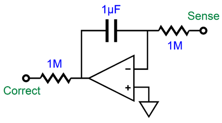
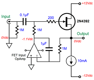
DC Servos A DC servo uses an amplifier (which might consist of a single electronic device, such as a single FET, tube, or transistor) and a DC negative feedback loop to establish a desired DC voltage, which is often 0V, but can be any desired DC voltage. (Many subwoofers that hold their own power amplifier an use bottom-facing woofers purposely use a small negative DC offset to pull the woofer cone up and its voicecoil back into the center of the magnet structure, after gravity has pulled them off alignment.) The keyword here is DC, as the DC servo should leave the AC signal unaltered. Here is a typical DC servo used to eliminate a DC offset voltage at the source-follower's output.
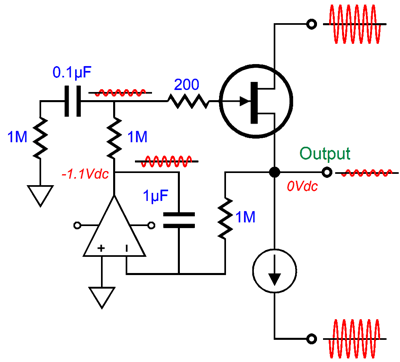
If the DC output goes positively above 0Vdc, the OpAmp responds to the voltage difference at its two inputs by making its output voltage go negative. How negative? Its output slowly drifts negative, until the source follower's output returns to 0Vdc. The inverse holds true if the follower's output goes negative instead, but the result is the same 0Vdc target DC output voltage. The FET's gate presents a supremely high input impedance, so we can use a fairly small-valued coupling capacitor (0.1µF) and a fairly large-valued gate resistor (1M), which form a high-pass first-order filter with a -3dB frequency of 1.59Hz. Dang low, in other words. (It's a good thing that our loudspeakers do not go this low, as subsonic frequencies can provoke spontaneous bowel movements, when the intestines encounter their resonant frequency.) The DC servo uses an OpAmp in an integrator topology, with its 1µF and 1M resistor defining a 0.159Hz transition frequency. Super dang low and a decade lower than the frequency the coupling capacitor imposed. When studying electronic servos, however, we will encounter this warning: at some frequency the servo will stop proving negative feedback and produce positive feedback, as no amplifier offers infinite bandwidth and constantly flat phase. This means that we must examine both frequency extremes, when dealing with DC servos. As you might imagine, there might be a phase lag between the DC servo's output and the follower's output, which will cause the servo to first over correct and then under correct and then over correct… If this results in a tiny slow rolling sinewave centered at 0Vdc at 0.1Hz, it is unlikely that even audio-magazine reviewers can hear it. If it occurs at 100Hz, then we all can worry. Okay, now let's try to think of ways that this system can actually go wrong. We assume that the OpAmp used offers a low DC offset, just as we assume that the yardstick is actually one yard long. If the OpAmp presents 10mV of DC offset, then the follower's DC offset will equal 10mV. OpAmps that hold transistor-based input stages require matching resistances at both inverting and non-inverting inputs. Feeding the non-inverting input zero ohms and the inverting input 1M ohms invites a DC offset, which is why FET-based input stages are preferred in DC servo OpAmps. Let's say that we are using an OpAmp with both an FET input stage and a naturally low DC offset, are we home free? Maybe, maybe not. What if the power supply that feeds the OpAmp is dirty and the OpAmp's PSRR poor? If so, then the power-supply noise will appear at the OpAmp's output, along with the correcting DC voltage. If the source follower's input is left floating, we can expect to hear 50% of the power-supply noise at the follower's output.
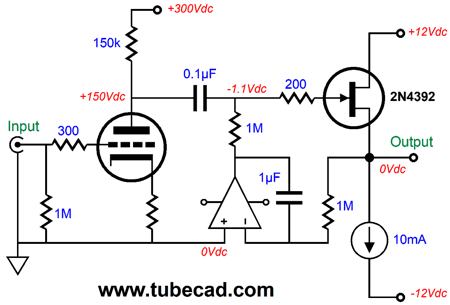
Why only 50% of the noise? The input 1M resistor and the 1M gate resistor define a two-resistor voltage divider. If the follower's input is attached to a low-impedance signal source, then the math works in our favor, as a voltage divider with 1M and 100 ohms allows very little (if any) of the DC servo's OpAmp noise to pass. What about a high-impedance signal source, let's say a grounded-cathode amplifier that uses a 12AX7?
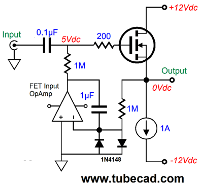
The output impedance of the 12AX7 in the above circuit is about 75k, which with the 1M gate resistor allows 7% of the OpAmp's noise to pass. If we choose an OpAmp with excellent PSRR or regulate its power-supply rails, then we have a lot less to worry about in this regard. One additional problem we might face is OpAmp latch up, where the OpAmp's output sticks to one power-supply rail voltage. One workaround is use to two two safety diodes, such as the 1N4148.
The diodes help prevent OpAmp from latching up. Some use diode-connected signal transistors instead, as they can offer lower leakage current; others paint the diodes so no light alters their performance.
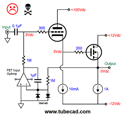
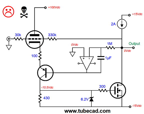
Nonetheless, I have had OpAmps latch up with the diodes in place. The workaround was simply to use a different OpAmp. Interestingly enough, old OpAmp designs often work best, such as the LF412, as do rail-to-rail designs, such as the AD823. With tubes, however, we can run into other problems, which is why I came up with my Broskie DC servo circuit. Here is a simple example: a unity-gain power buffer that uses a triode to drive an N-channel power MOSFET that is constant-current-source loaded. What's not to like?
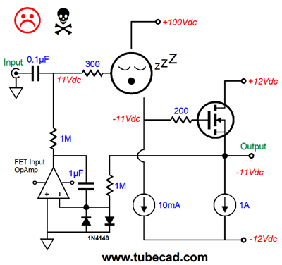
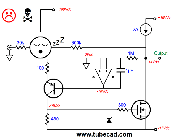
One huge problem is that the triode might not be located in its socket or it might be cold and not conducting; in either case, we have a big problem, as the buffer's output has slammed into the negative rail voltage.
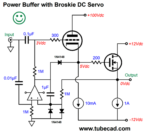
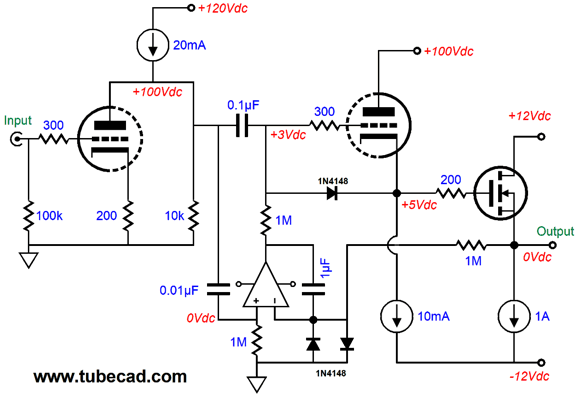
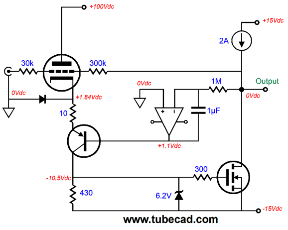
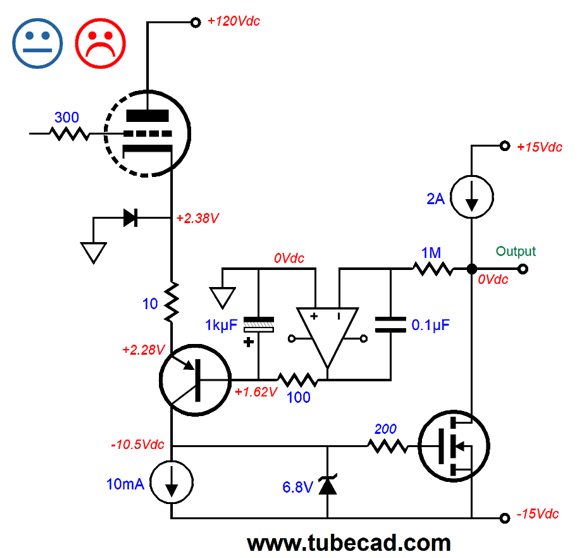
By time the triode heats up, the woofer will be singing in the heavenly choir. The workaround is to use a Broskie DC servo, as shown below.
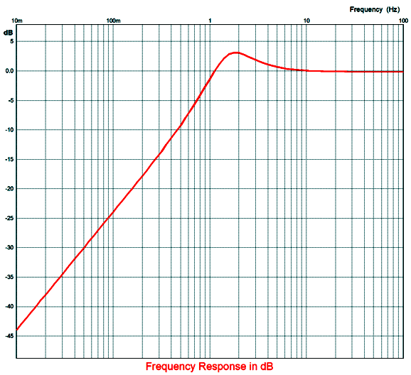
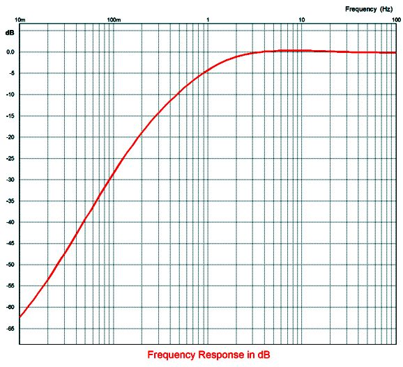
If the triode missing from its socket or its heater element opened up, the extra 1N4148 diode will become forward biased and conduct, allowing the OpAmp to undo any DC offset. As the music plays, the servo's output will trace the input signal, preventing the extra diode from engaging in an unwanted way. Note the decade staggering of the capacitor values. We use 1µF, 0.1µF, and 0.01µF capacitors. What happens if we use the same value, say 0.1µF, throughout? Not good, as get +3dB of peaking at 1.9Hz.
Of course, if we set a target frequency of 70Hz instead, those who own mini-monitor speakers might quite like the 3dB boost and the sharp cutoff, as it would allow the speakers to sound bigger and play louder before running into trouble. In other words, flat is not always best. In contrast, the decade staggered values result in only 0.5dB of peaking at 8Hz, as shown below.
What if we stagger in the opposite direction, so the DC servo gets the smallest capacitor value, while the non-inverting input of the OpAmp gets the biggest value? Answer, we end up with close to 1dB of peaking at 4.5Hz. Really, the best procedure is to model the circuit in SPICE and see what the low-frequency output looks like, as there might be a big bump at some subsonic frequency. Just for fun, let's use this power-buffer circuit in a complete amplifier.
The input tube provides all the gain and the output is inverted. Is that a problem? Only if you cannot flip the wires on your speaker terminals. By the way, the 1A constant-current source limits the maximum output swing to 8Vpk into an 8-ohm load, which equals 4W of power. Flea power, but mighty. The 10k plate load resistor is only there to limit the gain of the input triode; without it, the gain will come close to the amplification factor (mu) of the triode. We assume that the integrator capacitor coupling capacitor are blameless. Should we? No capacitor is perfect, as they all hold some series resistance and inductance. Even a straight piece of wire offers some resistance and some inductance. Here is an odd story. About two decades ago, a maker of high-end-audio capacitors sent me two of each of the values he made of his super-deluxe film capacitors to evaluate, with 400V and 630V capacitors in the array. I needed a pair of very high voltage capacitors in a project that I was assembling, a electrostatic headphone amplifier, so I used those first. Amazingly good sound, much better than the film capacitor I had been using (a Wima FKP-1 capacitor). I was so pleased that I replaced similar capacitors in another project. Not so good, as this time the Wima FKP-1 sounded better. This didn't make much sense to me, so I placed the 630V capacitors in the project and they did improve the sound. I then set up a test bed circuit and I evaluated each pair of capacitors. Starting at the smallest value, I got hit, fail, big hit, fail, big fail, hit, hit, big hit, hit-fail, and hit-fail. The hit-fail capacitors did some things really well and failed at other things. Yet, all the capacitors were made at the same factory with the same materials and techniques, with the only difference being that some used higher-voltage metallized polypropylene film. And, yes, I did perform some autopsies on the capacitors to see what was inside. One pattern that I noticed—and which I had noticed before—was that the smaller-valued capacitors tended to sound clangy, as if metal pots and pans were being banged around during a musical performance. In contrast, some of the larger-valued capacitors sounded dull, as if a curtain was placed in front of the musicians. There were exceptions, but that was the trend. Years prior, in 1971 when I was in freshman in high school, I held a sonic shootout on mylar-film capacitors (I didn't know that polypropylene and teflon film capacitors existed). I found that long, thin capacitors sounded better than fat, short capacitors. There was a clear winner brand that sounded best; sadly, I cannot remember exactly the brand today; I believe it was Marshall brand. Mind you, no one was talking capacitor sound back then and I had discovered the sonic differences by accident. After reading an article by David Weems in Popular Electronics on woofer arrays, I had built a dipole speaker that held four Philips 5in paper woofers with rubber surrounds in a long array and one Philips full-range with a whizzer cone and one 2in Peerless square tweeter on the back of the panel, firing backwards and out of phase. My stoner friends were dazzled by how holographic Pink Floyd albums sounded on these speakers, which were augmented by two 8in woofers in a center subwoofer with its own 35W amplifier. The rear-firing tweeter came in at about 8kHz to 10kHz and the 5in full-range started at 400Hz. I noticed that one speaker sounded better than the other. I localized the difference to the full-ranges, by disconnecting all the woofers. I then swapped full-ranges and the same panel still sounded better, so I switched their positions, left for right. The same panel still sounded better. I then measured the crossover capacitor values with my recently-built LCR made by Heathkit. Sure enough there was difference, with the better sounding panel holding a 52µF capacitor, while the other panel held a 49µF capacitor. I then dug out enough mylar capacitors to place in parallel with the 49µF capacitor to bring the non-polarized capacitor up to 52µF within a tenth of a microfarad. Okay, now the other panel sounded better, by a huge margin and I traveled down the path of sonically testing capacitors. I didn't have a driver's licence yet, but my loving father was kind enough to drive me all over Silicon Valley (and up into Oakland and Berkeley) to all the many electronic surplus stores that existed then in search of different capacitors to test sonically. Later, I went on a quest to find the best polystyrene capacitor. Some were just horrible sounding, with some Italian-made capacitors taking the prize for worst sound. The best was probably the Siemens Styroflex capacitors from Germany, but even they were not perfect. In short, replacing a 4µF coupling capacitor at the output with a DC servo that uses a 0.1µF internal coupling capacitor may result in better or worse sound due just to the capacitor changes, not the DC servo making things either better or worse.
DC Servo Trouble Ahead
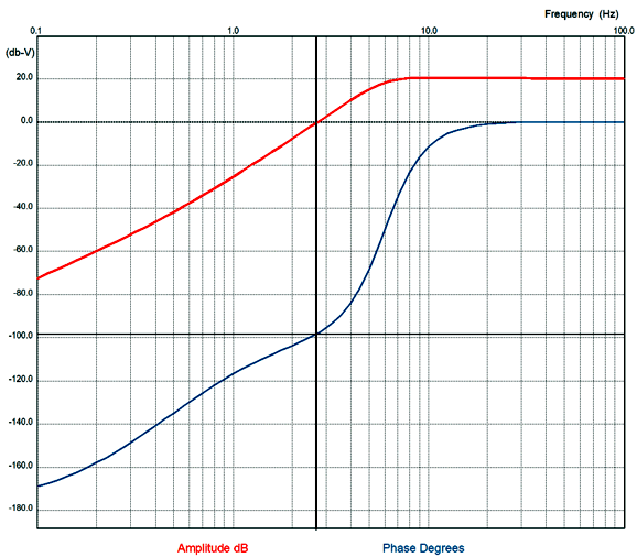
Why no happy face? The only time that I have personally run into DC servo problems was when I had to use the OpAmp's non-inverting input to sense the output DC offset voltage. Three capacitors are used and the staggering of time constants is critical. Here is the SPICE-generated low-frequency graph.
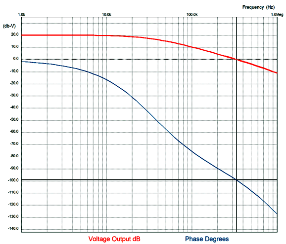
Note that there is about 0.3dB of peaking at 10Hz and the -3dB down frequency is 5.6Hz. The phase margin is a safe 82 degrees at the zero crossing. In other words, the output is not likely to oscillate, as a phase shift equal to 180 degrees would be needed while the amplifier is still delivering signal gain. Equally important are the high-frequency plots.
As you can see from the above graph, the -3dB down frequency is about 34.5kHz and the phase margin is a healthy 82 degrees. Remember that the assumption behind negative feedback is that the feedback remains negative, that it subtracts for the amplifier's gain. If it adds to the amplifier's gain, we have an oscillator. Thus, we never want the output phase to shift to close to 180 degrees while the amplifier is still maintaining gain. Okay, since getting three capacitor values right is a pain, why not just attach the DC servo's output elsewhere, so we can use its inverting input and a single capacitor?
Dang tempting, isn't? The big danger is, of course, that the triode might be AWOL or too cold to conduct.
The solution is to add one extra diode.
I forgot to add a happy face, so you will have to imagine that one is there. The diode saves the day, should the triode be missing from its socket or suffering from an open heater element. No doubt, many are thinking about adding an additional capacitor to the circuit, as shown below.
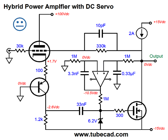
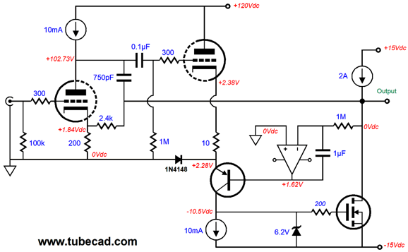
The logic behind such a move is that we do not want the OpAmp to directly drive the PNP transistor's base, so the added RC filter will buffer the base from the OpAmp's output. The added RC filter will buffer, but it will also add an additional time constant to the mix. Moreover, the electrolytic capacitor could become reversed biased, when the triode is missing or cold. (Use a non-polarized electrolytic capacitor instead.) In other words, this technique is best left to the advanced soldering-iron slinger. Just for kicks, I decided to flesh out this core design by adding an additional triode.
Now the amplifier has more gain to power the negative feedback loop. Moreover, the amplifier no longer inverts the phase. The only portion that is likely to cause concern is the 750pF capacitor. This capacitor improves the amplifier's phase margin by limiting the amplifier's open-loop high-frequency bandwidth. Trust me, it is essential. The tube that I used in my SPICE modeling was a 6DJ8 and the MOSFET an IFRP250. The constant-current loading of the single output MOSFET and the +/-15V power-supply rails set the maximum output swing into 8-ohm loads to about 12Vpk, which equals 9W into 8-ohm loads. Yes, we could back off on the constant-current source's current to 1.5A, but some headroom is always welcome to better deal with dipping speaker impedances. In SPICE simulations, the distortion at 1W was a lovely single-ended cascade and the THD came in at about 0.01%. Throw this circuit in a fancy box and slap a $10,000 price tag on it and you are off and running. Once again, this post has gotten much longer than I expected, so I will stop here, before the urge to draw more circuits grows too great to ignore.
//JRB
*Kant Bird Quote
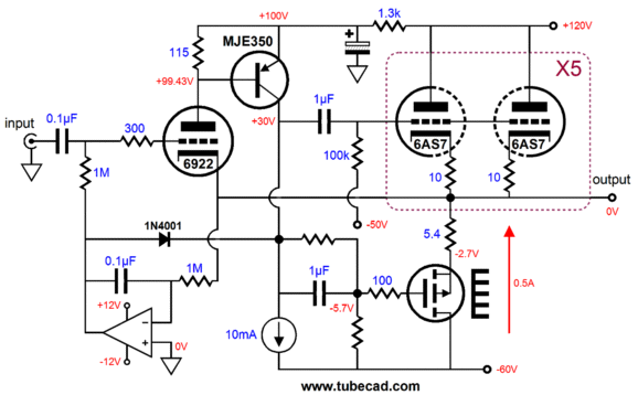
The 6922 triode controls the output stage in a super-triode fashion. Looking at it now, almost four years later, I would add a 100k resistor that would span the output to the B+ rail, so the P-channel MOSFET would have something to bite on at start up when the 6AS7 triodes are cold.
User Guides for GlassWare Software Since I am still getting e-mail asking how to buy these GlassWare software programs:
For those of you who still have old computers running Windows XP (32-bit) or any other Windows 32-bit OS, I have setup the download availability of my old old standards: Tube CAD, SE Amp CAD, and Audio Gadgets. The downloads are at the GlassWare-Yahoo store and the price is only $9.95 for each program. http://glass-ware.stores.yahoo.net/adsoffromgla.html So many have asked that I had to do it. WARNING: THESE THREE PROGRAMS WILL NOT RUN UNDER VISTA 64-Bit or WINDOWS 7 & 8 or any other 64-bit OS. One day, I do plan on remaking all of these programs into 64-bit versions, but it will be a huge ordeal, as programming requires vast chunks of noise-free time, something very rare with children running about. Ideally, I would love to come out with versions that run on iPads and Android-OS tablets.
//JRB |
Kit User Guide PDFs
And
High-quality, double-sided, extra thick, 2-oz traces, plated-through holes, dual sets of resistor pads and pads for two coupling capacitors. Stereo and mono, octal and 9-pin printed circuit boards available.
Designed by John Broskie & Made in USA Aikido PCBs for as little as $24 http://glass-ware.stores.yahoo.net/
The Tube CAD Journal's first companion program, TCJ Filter Design lets you design a filter or crossover (passive, OpAmp or tube) without having to check out thick textbooks from the library and without having to breakout the scientific calculator. This program's goal is to provide a quick and easy display not only of the frequency response, but also of the resistor and capacitor values for a passive and active filters and crossovers. TCJ Filter Design is easy to use, but not lightweight, holding over 60 different filter topologies and up to four filter alignments: While the program's main concern is active filters, solid-state and tube, it also does passive filters. In fact, it can be used to calculate passive crossovers for use with speakers by entering 8 ohms as the terminating resistance. Click on the image below to see the full screen capture.
Tube crossovers are a major part of this program; both buffered and un-buffered tube based filters along with mono-polar and bipolar power supply topologies are covered. Available on a CD-ROM and a downloadable version (4 Megabytes). |
||


| www.tubecad.com Copyright © 1999-2017 GlassWare All Rights Reserved |