| John Broskie's Guide to Tube Circuit Analysis & Design |
18 September 2017 Post Number 396
Special Thanks If you have been reading my posts, you know that my lifetime goal is reaching post number one thousand. I have 604 more to go. With only 4 more to go, I should easily be able to hit post 400 this year. My second goal is to gather 1,000 patrons. I have 948 patrons to go. If you enjoyed reading this post from me for the last 18 years, then you might consider becoming one of my patrons at Patreon.com. It would make a big difference to me. Thanks.
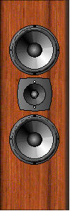
More Speaker Ideas Returning to the topic of email, one reader was shocked to learn that the classic Quad model 57 electrostatic speaker was not a fullrange, but a two-way design. What added to his embarrassment was that he had once owned a pair of Quads. He pointed out that in certain aspects, these old classics have yet to be surpassed. I agree. Paired with a good subwoofer and 100Hz crossover frequency, these electrostatic speakers can sing. Now, if Volkswagen can reintroduce the classic Beetle, why cannot Quad reintroduce the classic model 57, save for modern upgrades in materials and design features. Well, all this reminiscing about the old Quads, got me remembering my faux Quad speaker that I had built forty years ago, while in college. It was folded dipole that used an Audex 6in woofer and Audex 1in dome tweeter. I paired it with my 200lbs to 300lbs subwoofer and I used a 4th-order, 80Hz crossover frequency between the two. The results were quite good for the time. Like Jon Dahlquist, my aim was to build a speaker that not only looked like an electrostatic, but sounded like one, too. If I were to build similar dipole today, it would be much the same, save for using two woofers and one coaxial driver in the center. In other words, it would be a three-way speaker with 400Hz and 4kHz crossover frequencies.
The problem of maintaining an 8-ohm load impedance can be solved by using either two 4-ohm woofers placed in series or two 16-ohm woofers placed in parallel. In general, 16-ohm speaker drivers are rare. And the problem with 4-ohm drivers is that the stated SPL might prove disappointing. Why? SPL is usually tested with a calibrated microphone placed 1 meter away and 2.828Vavg (or 4Vpk) sine waves applied to the 8-ohm speaker, which equals 1W. If this same voltage is applied to a 4-ohm woofer, however, the wattage doubles. One watt into a 4-ohm woofer requires 2Vav (or 2.828Vpk) of signal. Yet, many 4-ohm woofers are advertised with the 2W amount of SPL, not 1W. One way that we can use two 8-ohm woofers is to place 8-ohm power resistors in series with each woofer, as shown below.
John, are you crazy? Those resistors will destroy the amplifier's damping factor! True, the damping factor will plummet, but that is just what I want. Why? Most woofers were designed for either acoustic-suspension (sealed box) or bass-reflex enclosures (ported), which means that they usually offer a low Qts (total Q), as the Q (quality factor or amount of peaking) in the enclosure will rise substantially. When used in a dipole non-enclosure, the electrical damping is far too high, resulting in a pinched bass response, as the woofers are over damped. Placing an 8-ohm resistor in series with the 8-ohm woofer, however, will increase its Qes (electrical Q), which when placed in parallel with the Qms (mechanical Q) will yield a higher Qts, allow more bass to be developed.
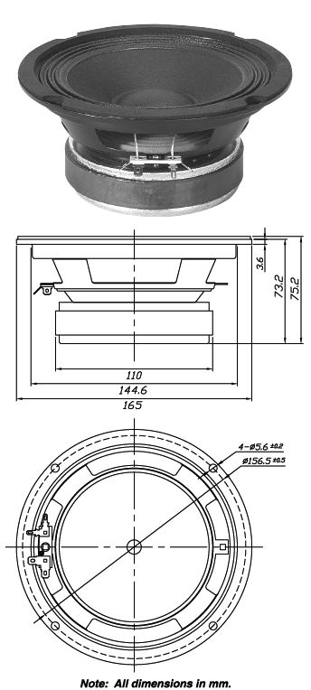
Reader, Christian, back in 2010 sent me an excellent email detailing why adding 2-ohms of resistance in series with an existing 8-ohm speaker was a bad idea, which is just what a late, sadly late, brilliant electrical engineer friend of mine had done in an attempt to make solid-state power amplifiers sound as good as tube power amplifiers. See my post from 2001 for the details on this EE's efforts and post number 186 for Christian's email. We can use the formulas that Christian provided to calculate the resulting Qts. Qes (new) = Qes*(R+RDC) / RDC Qes electrical part of woofers Q-Factor , R = added resistance of cable For example, the Dayton PA165-8 6in woofer holds the following specifications.
With the added 8-ohm resistor, we get the following changes:
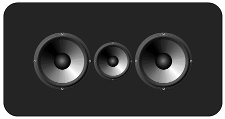
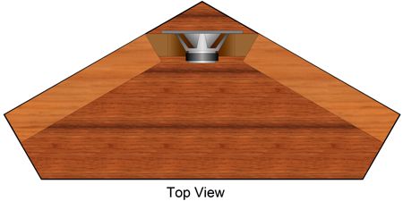
Note that the resonant frequency (Fs) and Qms did not change, but the Qes and Qts did. Qts equals Qes in parallel with Qms. A Qts of 1.065 equals 0.54 dB of peaking at the resonant frequency. What happens to the woofers SPL with the added resistors? Since each woofer now only sees 50% of the amplifier output voltage, its SPL falls by -6dB; but as we have doubled the emitting surface area by using two woofers, we gain +6dB of SPL, returning us to unity. In other words, oddly enough, the SPL remains unchanged in this arrangement. What if we used four woofers instead of two? The math is the same. Each woofer would need to get a 24-ohm power series resistor, so when the four 32-ohm loads are all placed in parallel, the resulting load impedance will be 8 ohms. Since each woofer sees only 25% of the amplifier output, we incur a -12dB drop in SPL from each; but as we have four woofers, we gain +12dB, bring us back to unity. (The same holds true for three 8-ohm woofers with 16-ohm series resistors.) Here is a dipole design that I would love to both build and hear.
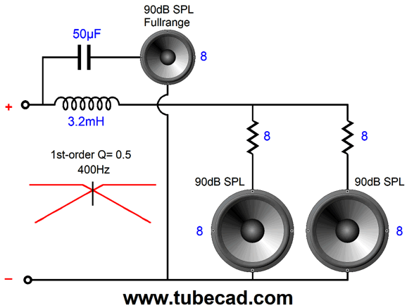
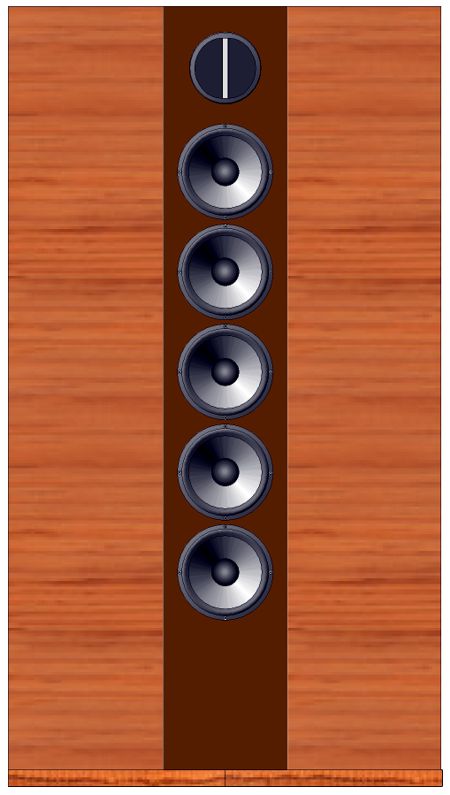
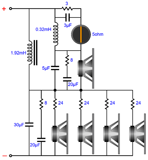
I had the decent Lack shelf units sold by Ikea in mind, when I came up with this design. Four 5in woofers offer a surface area equal to 10in woofer, but offer a much higher cutoff frequency and a greater ratio between voicecoil to diaphragm diameter. (I much prefer the increased articulation that a good 5in presents over a 10in or 12in woofer; and with four 5in woofer, we can get similar bass performance.) With the added 24-ohm resistors and a Dayton DC130A-8 5in woofer, just as an ready example, we get the following changes: Original with Resistors Qts = 0.41 1.1 Qes = 0.51 2.66 Qms = 1.9 1.9 Fs = 53 Hz 52 Hz A Q of 1.1 results in a 0.9dB of peaking at the resonant frequency, whereas a Q of 0.41 results in a -7.75dB droop at the resonant frequency. Many planar and electrostatic speakers run much higher, some closer to 2, as the peaking at diaphragm's resonance undoes some of the bass loss to the panel's width not being sufficiently wide to prevent bass cancellation. Here is what one possible crossover could look like for the above dipole.
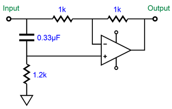
The 8-ohm resistors in series with a 20µF capacitor are Zobel networks that undo the effect of the woofer's own big internal series inductance. (All woofers with round voicecoils exhibit a good amount of inductance, which is why their impedance climbs at higher frequencies.) The tweeter that I had in mind was a 5-ohm ribbon and the 3-ohm resistor provides both the needed volume padding and brings its load resistance up to 8 ohms; the 3µF capacitor boosts the highs that begin to droop at ultra-high frequencies, starting at about 10kHz. Returning to the Quad-like dipole with two woofers, I was thinking about what a suitable crossover would look like when the following idea returned to my head. Back in post number 261, I pointed out that a phase-shifting but flat frequency response circuit could be used to achieve a crossover point—with no actual filter in place.
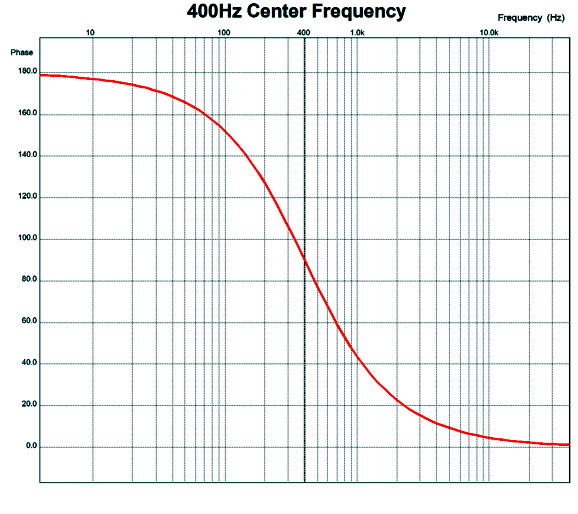
Below is the phase versus frequency graph, which begins at 4Hz and ends at 40kHz, thus centering at 400Hz on the log scaled horizontal axis.
The frequency plotline is a straight horizontal line that sits at 0dB, so I did not bother showing it. Using this topology with an internal (to the speaker) power amplifier allows us to do away with the passive crossover.
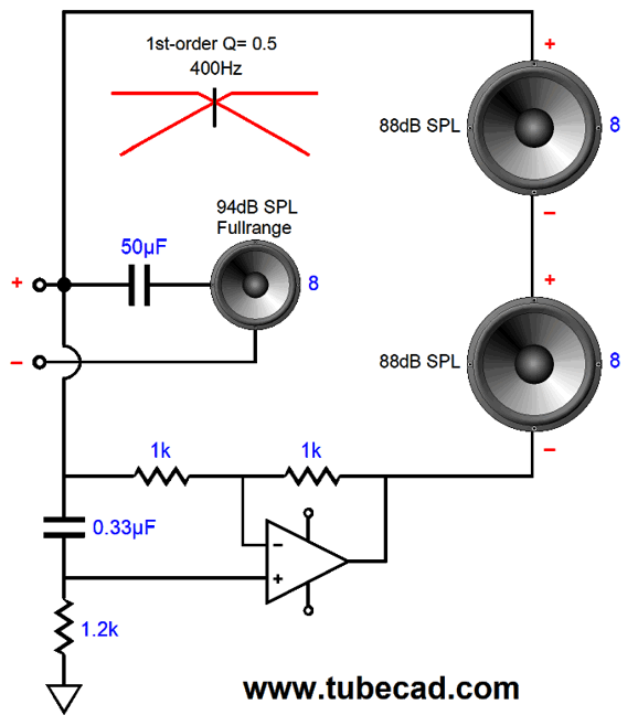
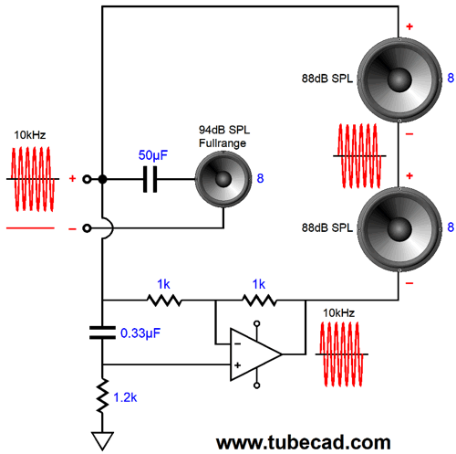
The solid-state power amplifier that feeds the two woofers in series puts out a flat frequency response, but inverts DC and low frequencies, while delivering high frequencies in phase. The result is that the two woofers see a differential signal at low frequencies, but no differential signal at high frequencies; and since a speaker driver is an intrinsically differential device, giving it the same signal—in phase—at both its terminals results in no sound.
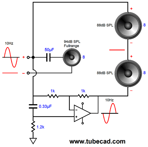
Note how the the 10Hz signal is inverted by the internal amplifier. Also note how no signal appears at the nexus between drivers. Also note that booth woofers work in phase, but the bottom woofer's negative terminal attaches to the internal amplifier's output. At high frequencies, however, the phase is restored. Since neither woofer sees any voltage differential across its terminals, they remain still.
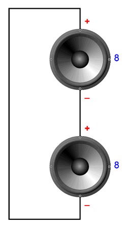
As far as the external power amplifier is concerned, which might be a flea-power tube amplifier or a behemoth solid-state power amplifier, the woofer impedance it sees at low frequencies is 8 ohms, not 16 ohms. And as the frequencies climb above the crossover frequency, the woofer impedance increases as if it were in series with an inductor. In other words, with the fullrange driver in place, the external power amplifier thinks it is driving a consistent 8-ohm load. As far as the two woofers are concerned, at high frequencies, they act as if they were situated in the following circuit.
Note that no inductor is used. Is that a good thing? You betcha. Why? Think about it: you have just bought $22,000 speaker cables, confident that all the sonic purity will now easily flow into your speakers, as the speakers are no longer choked by the cheap $2,200 cables you were using. Yet, the same inductors are still located within the speaker's crossover, so all that sonic purity must flow through several hundred feet of 22-gauge enameled wire. (If only they sold $45,000 inductors.) In contrast, the two woofers in this scheme see only the two amplifier outputs, so all of the damping factor can apply and all the sonic beauty can flow pour forth freely. Since each woofer sees the same differential signal voltage that the fullrange sees, and since we are using two woofers, we gain +6dB at low frequencies, which means we can use 88dB woofers with a 94dB fullrange driver. The power amplifier internal to the dipole speaker effectively doubles the power going to the woofers. Thus, if a 16W single-ended tube-based power amplifier puts output 16Vpk at 100Hz, the internal amplifier will also put out -16Vpk, adding up to 32Vpk, which across a 16-ohm load equals 32W. Note that if the external power amplifier clips smoothly and if the internal power amplifier has not exceeded its maximum output, the internal amplifier will put out a smoothly clipped output. In other words, the internal power amplifier will mimic the external power amplifier's flavor. Isn't adding a power amplifier to a speaker a pain? Yes, it is; but so is dealing with big inductors. Ideally, we use an internal power amplifier only slightly more powerful than the external amplifier. But as class-D amplifiers are so cheap and so powerful, we could simply use a one-size-fits-all amplifier with 200W of output. (By the way, from my listening test, I quite like class-D amplifiers as long as they are not used with differential outputs and as long as they are not required to go beyond about 3kHz. Unfortunately, just about all class-D amplifiers hold inductors at their outputs; fortunately, these are low in value.)
SRPP Power Amplifier
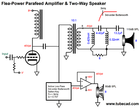
One reader wondered why the following Schematic from post number 394 utilized so small a plate voltage swing, only +/-40Vpk, whereas most single-ended power amplifier saw swings almost ten times greater.
The idea behind that design was that the load to be driven was a super-high-efficiency horn-load tweeter, so only 1W was needed. If we doubled the plate voltage swings, we would get 4W of output. Double the swings again, for 160Vpk, and we get 16W of output. Mind you, the idle current must be sufficient to sustain these larger plate-voltage swings. In the above schematic, we see an output transformer winding ratio of 10:1, which results in an impedance ratio of 100:1, so that 8-ohm load reflects to the primary as 800 ohms. Now, 160V divided by 800 ohms equals a peak current swing of 200mA, which must also be the idle current. This is not trivial amount of current flow, as it against 300V of cathode-to-plate voltage equals 60W of plate dissipation. In contrast, a class-A push-pull output stage need idle at only half the peak current swing. In this example, 100mA, which against 300V equals only 30W of dissipation. Of course, push-pull also means two output devices, so a total of 60W of plate dissipation remains: a giant step sideways, as I like t say. Or does it? If two output tubes are used, then certainly 60W of plate dissipation remains. If we use one output tube and one solid-state output device, say a power MOSFET, then we can get away with less dissipation.
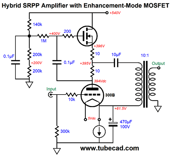
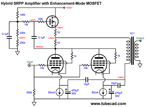
Note that the B+ voltage is only high enough to ensure positive 160V plate-voltage swings. Also note that the topology is a hybrid SRPP, which pushes and pulls, resulting in up to twice the idle current being delivered into the primary and, by extension and increased by the winding ratio, into the external load. In other words, the 200mA swings become 2A swings into the 8-ohm speaker, which creates 16Vpk voltage swings at the secondary and 16W into 8-ohm loads. Beyond saving on expensive output tubes, this hybrid SRPP power amplifier offers excellent PSRR, as the MOSFET's drain offers wonderful shielding of power-supply noise to the output triode's plate. The output transformer is capacitor coupled, so its sees no net DC current flow and need hold no air-gap. The bottom lead of the output transformer's primary is attached to the output triode's cathode. Why? So that cathode's bypass capacitor is out of the current loop with the output transformer. The two diodes are there as safety devices, which prevent inductive kickbacks from taking out the power MOSFET. The constant-current source auto biases the output stage and can be made from a TL783 high-voltage, adjustable regulator. The MOSFET only dissipates 114.4W, while the triode dissipates 33W. Effectively, the SRPP topology make the external load appear twice as large than it actually is to the output triode, so the 800-ohm primary impedance appears as a 1600-ohm load to the triode, which will lower the triode's distortion. Of course, different output tubes could be used, as could different output transformers. For example, an output transformer with a winding ratio of 14.14, like my favorite UBT-1 transformer, offers an impedance ratio of 14.14², or 200:1, so 8-ohm loads appear as 1600-ohm loads at the output tube's plate. And two KT77 or KT88 output tubes could be used in parallel, as shown below.
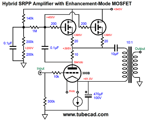
Each triode-connected pentode gets its own constant-current source cathode load, so each can auto-bias correctly. Note that two 10µF capacitors are used at the bottom of the primary, as the two cathodes are unlikely to be at the same DC voltage. If we wish, we can also double up on power MOSFETs, as shown below.
Note how only one current-sense resistor is used, but two 20-ohm source resistors are used. Why two? Giving each power MOSFET its own source resistor will help ensure equal functioning between power MOSFETs and prevent current hogging, where one MOSFET hogs too much current flow, although this is, in general, far less a problem with MOSFETs than it is with transistors. Also note that two 20-ohm resistors are used, not two 10-ohm resistors. Think in terms of impedance-multiplier circuit (IMC), not SRPP, as that is what the MOSFET are doing in this circuit—with little regard to the 300B, as its mu and rp do not matter to the IMC.
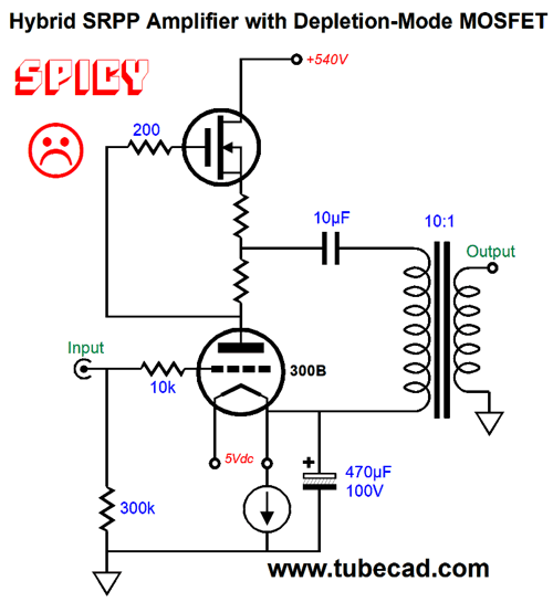
Some might query the need for the 0.1µF internal coupling capacitor, believing that it could be left out, as it is in the following schematic.
A very bad idea. This arrangement might work in SPICE, with a depletion-mode MOSFET, but it is unlikely to work in reality. The internal coupling capacitor and two-resistor voltage divider, in contrast, ensure a fair voltage distribution between MOSFET and output tube.
//JRB
If you enjoyed reading this post from me, then you might consider becoming one of my patrons at Patreon.com.
User Guides for GlassWare Software
For those of you who still have old computers running Windows XP (32-bit) or any other Windows 32-bit OS, I have setup the download availability of my old old standards: Tube CAD, SE Amp CAD, and Audio Gadgets. The downloads are at the GlassWare-Yahoo store and the price is only $9.95 for each program. http://glass-ware.stores.yahoo.net/adsoffromgla.html So many have asked that I had to do it. WARNING: THESE THREE PROGRAMS WILL NOT RUN UNDER VISTA 64-Bit or WINDOWS 7 & 8 or any other 64-bit OS. I do plan on remaking all of these programs into 64-bit versions, but it will be a huge ordeal, as programming requires vast chunks of noise-free time, something very rare with children running about. Ideally, I would love to come out with versions that run on iPads and Android-OS tablets. //JRB |
E-mail from GlassWare Customers
High-quality, double-sided, extra thick, 2-oz traces, plated-through holes, dual sets of resistor pads and pads for two coupling capacitors. Stereo and mono, octal and 9-pin printed circuit boards available.
http://glass-ware.stores.yahoo.net/ Support the Tube CAD Journal & get an extremely powerful push-pull tube-amplifier simulator for TCJ Push-Pull Calculator
TCJ PPC Version 2 Improvements Rebuilt simulation engine *User definable
Download or CD ROM For more information, please visit our Web site : To purchase, please visit our Yahoo Store: |
|||


| www.tubecad.com Copyright © 1999-2017 GlassWare All Rights Reserved |