| John Broskie's Guide to Tube Circuit Analysis & Design |
24 August 2018 Post Number 436
Return of the Triadtron
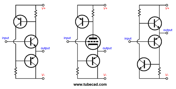
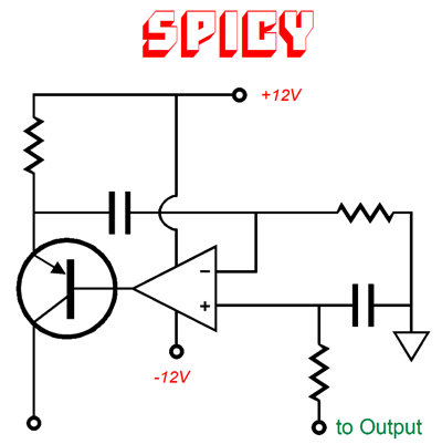
In case you have forgotten the Triadtron, be sure to check out post 188. Here the core of the new circuit.
The NPN transistor receives the input signal at its base and its collector resistor reveals the current flow through the transistor. If the current flow is too great, the top PNP transistor will turn on and draw current, which in turn will force a greater voltage drop across its collector resistor, which will then force the bottom PNP transistor's base to move up in voltage. Equilibrium obtains when the NPN collector resistor sees the same voltage drop as the top PNP transistor's base-to-emitter voltage. In other words, auto-bias. Because of the auto-bias feature, the NPN transistor's idle current barely varies, whereas the bottom PNP transistor will undergo all the current variations needed to drive an external load impedance. Thus, the single-ended aspect of the circuit. This is an inversion of the single-ended emitter follower circuit wherein the emitter works into a constant-current source. In that setup, the constant-current source's current never varies, while the NPN transistor's varies with the input signal and external load impedance sees the difference in current conduction. The next step is to add an input emitter-follower stage to reduce the input impedance and to add a few stability capacitors and to add a DC servo loop to keep the output centered at the ground potential; i.e. no DC offset voltages. The OpAmp monitors the DC offset at the output and varies the base voltage of its PNP transistor to counter the offset voltage. In other words, the OpAmp and PNP transistor define a variable-current source. If the output strays too positive, the variable-current source draws less current, which will lower the NPN transistor's base voltage and the output will drop back to 0V. If the output drops below 0V, the variable-current source draws more current, which will force the output back to 0V.
The OpAmp is powered by the +/-12V power-supply rails and should hold an FET input stage; it could be a dual-OpAmp type. Note that this DC servo may not look right, as the Triadtron's DC output enters the OpAmp's non-inverting input, not its inverting input, which is the typical arrangement. This seeming conflict is resolved when we realize that the PNP transistor is part of the DC servo and this transistor inverts the signal at its base, so the OpAmp's non-inverting input effectively becomes an inverting input for the entire DC servo.
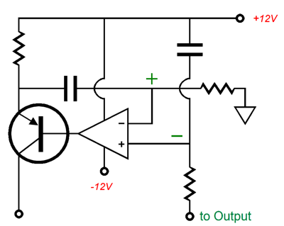
Note how one capacitor terminates into the +12V power-supply rail. This is critical, as it establishes a quiet DC servo. The following messed-up version must be avoided.
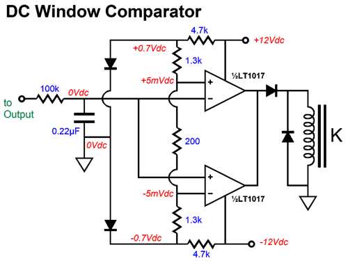
This version works flawlessly—in SPICE simulations, but bombs in reality. Why? The emitter resistor must see 100% of the +12V rail noise at both its ends, as that will ensure that the power-supply noise will not leak into the DC servo's output. By the way, even with the DC servo in place, I would think about adding a protection relay at the output. Why? DC and expensive headphones should never meet. The relay can be driven by window-comparator circuit, which would only engage the relay and close its contacts when the DC offset hits 0V (that is it falls between 5mV and -5mV). Note the two diodes, which serve as voltage references. Once again, SPICE offers the trap false exactitude, as real +/-12V power supply rail voltages might actually measure +11.8Vdc and -12.3Vdc and real 200-ohn resistors can fall between 198 and 202 ohms and still be 1% types. With the diodes in place, we could run unregulated +/-12V rails.
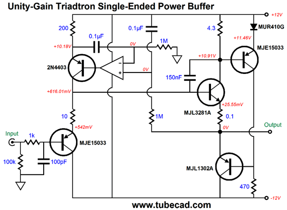
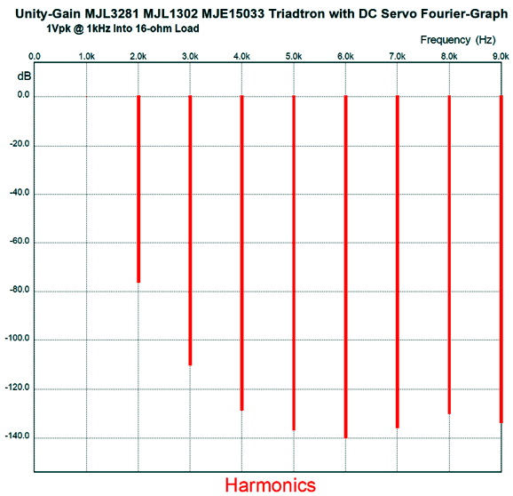
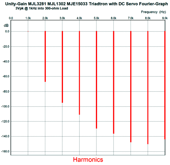
How would we use this window comparator circuit? We would place a large-valued resistor in series with the output, say 10k, and the relay would normally remain open; thus, the headphones will only connect to the output through the 10k resistors, until the 12V relay closes its contacts. Lest you worry about the relay contacts sullying the sound, many communication-grade relays are sold with hard-gold contacts. (The LT1017 is probably overkill, but it was the only high-output-current comparator I could think of off the top of my head. If more current is required, the LT1018 offers about twice as much as the LT1017.) How does this Triadtron buffer perform? Here the SPICE-generated Fourier graph for 1Vpk into 16 ohms at 1kHz.
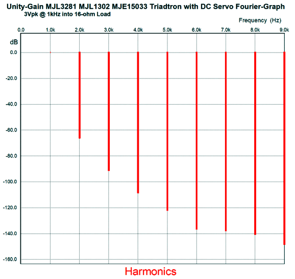
The THD comes close to being 0.01%, but more important to me is the relative ratios of even to odd harmonics. This is a truly single-ended fingerprint. Now, let's look at 3Vpk, which is 280mW into 16-ohm loads.
The THD climbed a bit, but note that 7th, 8th, and 9th harmonics actually went down, not up. Okay, what if we drive 300-ohm headphones instead?
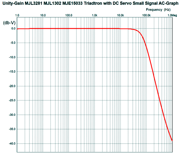
The Triadtron's NPN transistor idles at about 250mA, so that is the peak output current swing. With 32 ohm headphones, the peak output voltage swing would be 32 against 0.25A, which equals 8Vpk, which in turn equals 1W of power. The output impedance was about 0.3 ohms. The frequency response is flat and falls off at 72kHz.
Understand, that this buffer offers no voltage signal gain, only current gain, so it relies on the signal source for a sufficiently big input signal. This is all nice, John, but where are the tubes? Tubes, you want tubes? Have I got tubes for you.
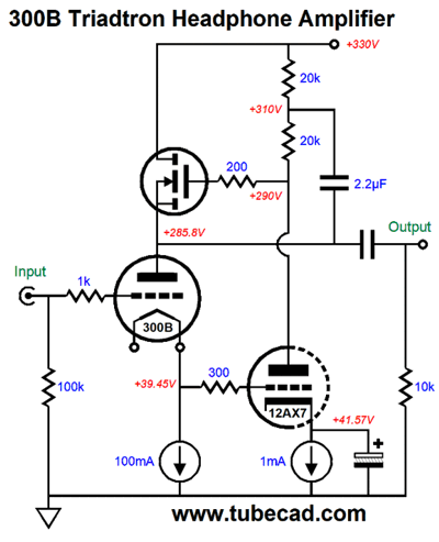
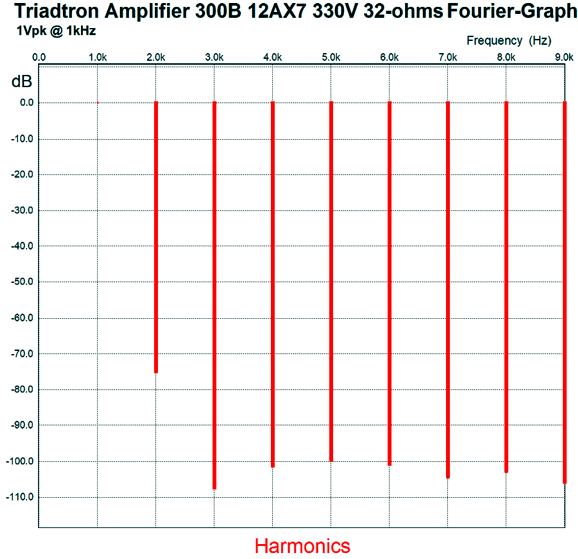
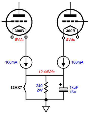
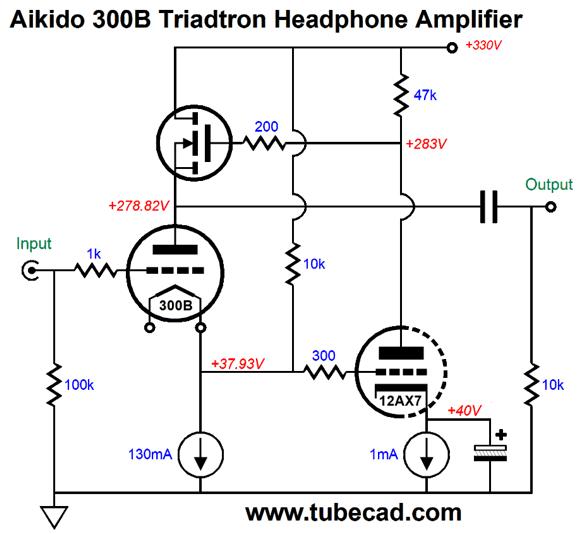
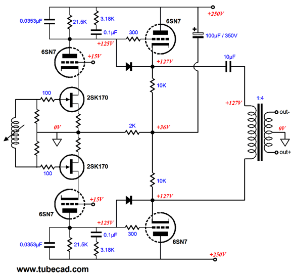
300B-Based Triadtron Headphone Amplifier We can give this starring role to many triodes, such as the 2A3, 6AS7, 6H30, 12B4, but one stands out: the 300B. The 300B is certainly the star of many emails that I receive and when I have asked tube-loving folk what sort of headphone amplifier would they like most, the answer I most often hear is 300B-based headphone amplifier. Even one friend who actually disdains the 300B in power amplifiers that drive loudspeakers said he would like a 300B headphone amplifier. Was he being inconsistent? At first, I though so. But with some reflection, I believe I understand his reasoning. His complaint against the 300B in power amplifiers is that its highs seem dimmed; in a headphone amplifier, however, this failing might prove a feature. In fact, I have told here of my experience with some old Telefunken 12AU7 tubes that I discovered that I owned. At first, I was disappointed, the sound seeming somewhat dull and reticent, certainly sparkle free, but I could not stop listening to music. With the headphone diaphragms just an inch away from your eardrums, how much sparkle is too much sparkle? The 300B maximum steady current flow is 100mA, which will set the limit of the maximum output current swing. This limit implies a maximum peak voltage swing of 30V into a 300-ohm load and 1.6V swing into 16 ohms, which results in 1.5W and 80mW respectively. With a 50-ohm load, we get 250mW. Let's now look at the Triadtron amplifier configuration.
The 300B is auto-biased by the 100mA constant-current source at its cathode, while the 12AX7 is as well by its 1mA CCS. The 300B's directly-heated cathode attaches to a floating 5Vdc power supply, preferably a regulated one. The way this circuit works is that 12AX7 monitors the 300B cathode voltage and responds to any changes in voltage. If the 300B's cathode voltage moves up, say in response to a positive 1V signal at its grid, the 12AX7 increases its current conduction and pulls down the N-channel MOSFET's gate voltage, which in turn will lower the 300B's plate voltage. By how much? As much as is needed to return the 300B's cathode voltage to its idle value; in other words, by the amplification factor (mu) of the 300B, which is roughly 4. If a 40-ohm headphone driver attaches to the output, the headphone will see a -4Vpk voltage swing and a 100mA current swing. Conversely, if 300B's cathode falls, the 12AX7 will force the MOSFET's source up until the idle voltage is reestablished. The 300B will undergo an almost constant-current conduction (100mA), while the MOSFET will undergo current swings of +/-100mA. Thus, you can see the single-ended and super-triode aspects of this circuit. What is the output impedance of this amplifier? Far, far lower than you might imagine. In SPICE simulation the result was lower than 1 ohm. The Fourier graph of the harmonics was quite good.
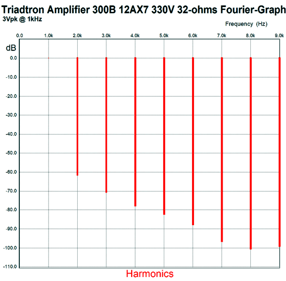
Behold the lower-than-expected 3rd harmonic. It is about -20dB lower than what is typical. Now, lets increase the output signal to 3Vpk into 32-ohms, which equals 140mW.
The THD is about 0.1% and smoothly single-ended in structure. What is there not to like about this design? Well, other than the expense of two 300B tubes, having to provide three heater power supplies is a pain, 5V, 5V and 12.6V. One workaround would be to commandeer or highjack the needed current from elsewhere in the circuit. For example, since the goal is that the 300B's cathode does not vary in voltage and that its plate current remains close to constant, we can divert the current flow from both channel's constant-current sources to the 12AX7 heater.
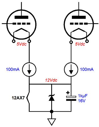
Since the 12AX7 heater element only draws 150mA of current, we place the 240-ohm resistor in parallel with it to bring the total current flow up to 200mA. Alternatively, we can replace the resistor with a 12V zener.
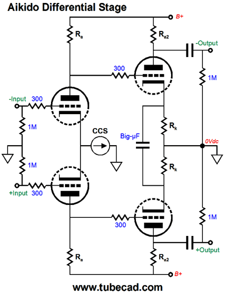
Another complaint we might make is that the faux constant-current source created by the two 20k resistors and the 2.2µF capacitor is lacking in elegance. Well, we cannot use an actual constant-current source in their place, as we never want to place two constant-current sources in series, they will lead to headaches. One workaround is to introduce some Aikido mojo.
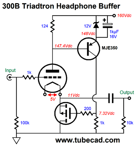
The 10k resistor will dissipate a lot of heat, so a high wattage type is required. In addition, the constant-current source must supply both the 300B and this added resistor their needed current flow. I can imagine that either design would make a fine looking headphone amplifier. Just imagine one 12AX7 and two 300B tubes on a chassis top. Most would assume that the 12AX7 was the input tube, not the 300B, and that the 12AX7 controlled the 300B, not the other way around. In the buffer version of the Triadtron, we lose the 12AX7.
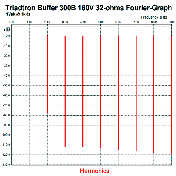
This power buffer offer no signal gain, so the signal source must provide the needed signal gain. The MJE350 PNP transistor monitors the 300B current flow by reading the voltage drop across the 124-ohm plate resistor. The 12V zener allows us to use larger-valued plate resistor and the 1kµF shunting capacitor across the zener undoes most of the zener noise. The P-channel MOSFET performs the same job as the N-channel MOSFET had performed in the amplifier version: It varies its current conduction so the 300B's conduction remains constant. The P-channel MOSFET model used in SPICE simulations was of an IRF9520. Note the low B+ voltage in the design, 160V, not 330V. This relatively low B+ voltage allows us to use a 300V PNP transistor and greatly reduces the 300B's dissipation. In addition, we get to use a far lower voltage output coupling capacitor. This is important, as 16-ohm headphones will require at least 500µF of capacitance to go down to 20Hz. With the 400B's 11V cathode voltage, we can use a 16V or 25V non-polarized coupling capacitor (bypassed by a quality film or PIO capacitor). Here is the Fourier graph for 1Vpk at 1kHz into 32-ohm load.
Note that once again the 3rd harmonic is lower than what we might expect. Reducing the 3rd, 5th, and 7th harmonics is the goal. Now, here is the 3Vpk graph.
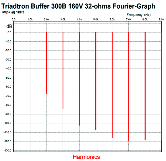
Not bad at all. Very single-ended, the THD is definitely lower than the amplifier version, as we would expect. (I did try a version without the 12V zener and with a lower-valued plate resistor, but the distortion was much too high.) In SPICE simulations, the output impedance was less than 0.1 ohms! On the other hand, the PSRR was only -14dB. Therefore, I would use a regulated power supply. (I would use a PS-21 with 250V capacitors and 5Vdc heater regulator outputs.) Still, this circuit is simple and the 300Bwill last much longer due to the reduced plate dissipation. If line-stage amplifier is used to drive the buffer, this Triadtron would certainly be worth considering.
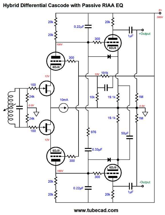
Balanced Phono Stage First, let's look a design from post 323 that presented no issues. This hybrid phono stage uses cascading differential amplifiers with some Aikido mojo thrown in to improve the signal-to-noise ratio by vastly improving the PSRR.
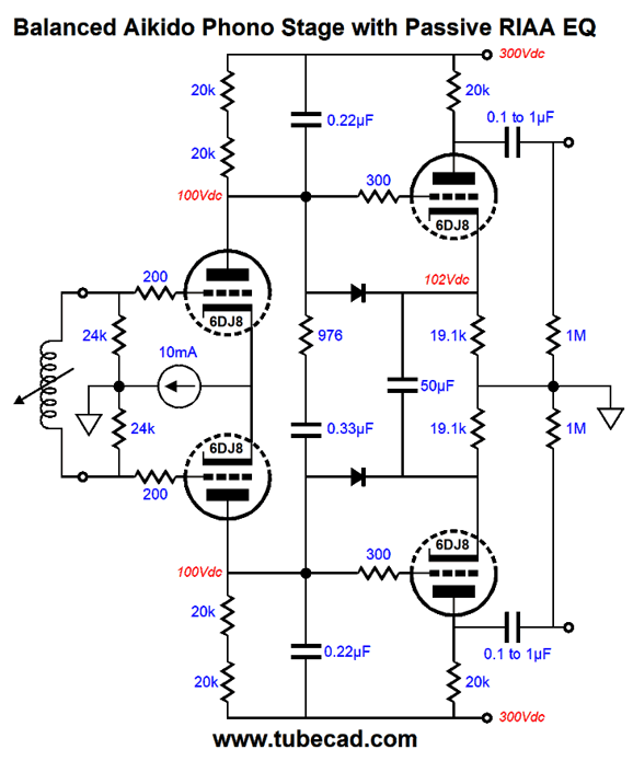
The N-channel FETs cascode into the triodes above them, so any current variation passes through the triodes and develops a varying voltage across the plate resistors. The plate resistor are not naked, as they are adorned with RIAA equalization capacitors and resistors. Note how the equalization is referenced to the B+ voltage connection, not ground. The balanced output signal then cascades into the two cathode followers, which are also referenced to the B+ voltage connection through the 100µF capacitor. If you must, think of them as ultra-path cathode followers. In other words, the phono cartridge and FETs are ground-referenced, but the cascode plate resistors and RIAA equalization parts and cathode followers are all B+ voltage referenced. If we took the output signal directly from the cathode follower outputs, the PSRR would be zero, as 100% of the power-supply noise would be superimposed upon the output signal. But as the output transformer is an intrinsically differential electrical device, the power-supply noise is treated as common-mode signal and ignored. Another advantage to the output transformer is that it can deliver more signal gain, if needed. Okay, what if we didn't want to buy expensive signal transformers? One workaround would be to use the Aikido differential gain stage from post 381.
The shared constant-current source by the two input triodes ensures a PSRR approaching zero, which normally would prove a huge liability, but in this circuit it is a feature. The second differential amplifier hold optimally chosen plate and cathode resistors values to provoke a power-supply-noise null that the two outputs. The Big-µF polypropylene capacitor that spans the two cathodes effectively unites the cathodes in AC terms, but allows for big DC voltage differences to exist without causing harm. Now, all we need to do is add the RIAA equalization parts—but with a twist, as 500Hz-pole-setting resistor (976 ohms) and capacitor (0.33µF) span from plate to plate. (The diodes are only safety devices that only engage when the power is applied and the tubes are still cold. If they bother you, imagine that they are not there)
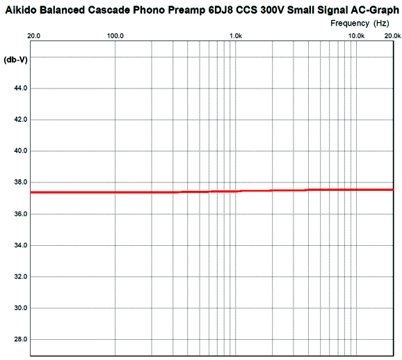
This is the final design. (As if any design is final, i.e. not subject to modification.) I would use several LM334Z constant-current sources in parallel, which would all the them to work within the 2.3V voltage window and reduce their noise contribution If the RIAA equalization part values look crazy to you, you are not alone, as they looked crazy to me as well. In fact, the only values that made sense was the 976-ohm resistor and 0.33µF capacitor, which is where I started the design. Once I had the bottom half of the reverse RIAA equalization curve, from 50Hz to 500Hz, flat, I went after the second half, the low-pass filter at 2122Hz. Here is the SPICE-generated frequency response graph.
Not bad. Its flat within 0.2dB from 20Hz to 20kHz. (I purposely aimed to make easily-available capacitor and resistor values work. If ideal, absolute resistor and capacitor values were used, the curve would prove flatter still.) The gain comes in at about 38dB, which is only 2dB shy of the standard 40dB for phono preamps. If more gain were needed, a step-up transformer could be used. Or, we could use the FET cascode in the first differential gain stage. (Many of my LP-loving friends tell me the same story: they buy a step-up transformer and later replace it with an active pre-preamp gain stage, which then gets replaced by the old step-up transformer, as it ultimately worked better.)
A negative power-supply rail (-5V) might be needed to give the constant-current source more voltage headroom.
Quick Update
Just the other day, a friend and I were talking about how headphones systems were the optimal first step for young music lovers. If nothing else, great-sounding headphones for far less than a decent high-end-audio power cord. (Imagine the dilemma: a 20-yearold must choose between a new $1,000 smart phone or a $1,000 high-end-audio power cord.) I pointed out that I drop into Best Buys electronics store at least once a month and, when I do, I always check out their high-end room, where they keep their best TV screens and expensive loudspeakers. The room is always empty. In contrast, out in the two isles that hold fancy headphones, I often encounter enthusiastic teenage boys and young men. Last week, I observed two college students compare as many headphones as they could. Their conversation was filled with comments that you would expect to hear at a stereo show. "The bass is big, but too flabby. Extended highs, but oddly disjointed from the rest of the frequency spectrum. Amazing clarity…"
I was tempted to interject myself into their conversation and tell them that they must attend the upcoming Can Jam at the RMAF in Denver in October, where they could hear great $50 earbuds and $50k headphone systems. Ideally, all the nearby colleges should each charter a bus and fill it with students, so the students could spend half a day at the Can Jam. After just one event, the number of newbie audiophiles living in or near Denver would increase tenfold.
Music Recommendation: Silent Running (Movie Soundtrack) Actually, many movie soundtracks are worth hearing. Anything by Bernard Herrmann is worth a listen. He composed the music for the movie, Psycho, and Alfred Hitchcock said that a third of the movie's scariness was due to Hermann's music. In fact, if a movie is deemed to be a classic, Herrmann probably composed the music for it; for example, Citizen Kane (1941), The Devil and Daniel Webster (1941), Jane Eyre (1944), Anna and the King of Siam (1946), The Ghost and Mrs. Muir (1947), The Day the Earth Stood Still (1951), North by Northwest (1959), Fahrenheit 451 (1966), and Taxi Driver (1976). Do check out The Fantasy Film World Of Bernard Herrmann and The Mysterious film world of Bernard Herrmann.
Harry Pearson, the man behind The Absolute Sound, included this last album on his super LP list. Aaron Copland, Erich Korngold, Prokofiev, Shostakovich—all wrote music for movies. And many jazz greats made music for movies. Alas, much of this great music is forgotten, as we have forgotten the movies.
//JRB
If you enjoyed reading this post from me, then you might consider becoming one of my patrons at Patreon.com
User Guides for GlassWare Software
For those of you who still have old computers running Windows XP (32-bit) or any other Windows 32-bit OS, I have setup the download availability of my old old standards: Tube CAD, SE Amp CAD, and Audio Gadgets. The downloads are at the GlassWare-Yahoo store and the price is only $9.95 for each program. http://glass-ware.stores.yahoo.net/adsoffromgla.html So many have asked that I had to do it. WARNING: THESE THREE PROGRAMS WILL NOT RUN UNDER VISTA 64-Bit or WINDOWS 7 & 8 or any other 64-bit OS. I do plan on remaking all of these programs into 64-bit versions, but it will be a huge ordeal, as programming requires vast chunks of noise-free time, something very rare with children running about. Ideally, I would love to come out with versions that run on iPads and Android-OS tablets. //JRB |
John Gives
Special Thanks to the Special 67
I am truly stunned and appreciative of their support. In addition I want to thank
All of your support makes a big difference. I would love to arrive at the point where creating my posts was my top priority of the day, not something that I have to steal time from other obligations to do. The more support I get, the higher up these posts move up in deserving attention. Only those who have produced a technical white paper or written an article on electronics know just how much time and effort is required to produce one of my posts, as novel circuits must be created, SPICE simulations must be run, schematics must be drawn, and thousands of words must be written.
If you have been reading my posts, you know that my lifetime goal is reaching post number one thousand. I have 564 more to go. My second goal is to gather 1,000 patrons. I have 933 patrons to go. Help me get there.
Support the Tube CAD Journal & get an extremely powerful push-pull tube-amplifier simulator for TCJ Push-Pull Calculator
TCJ PPC Version 2 Improvements Rebuilt simulation engine *User definable
Download or CD ROM For more information, please visit our Web site : To purchase, please visit our Yahoo Store: |
|||


%20Cover.jpg)


| www.tubecad.com Copyright © 1999-2018 GlassWare All Rights Reserved |