| John Broskie's Guide to Tube Circuit Analysis & Design |
30 November 2018 Post Number 448 New Product From GlassWare
The Balancer
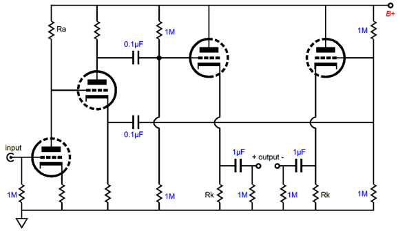
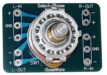
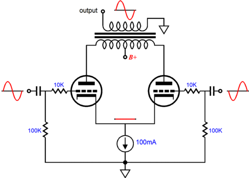
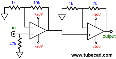
From the above schematic (simplified), we can see that the Balancer's input stage is a grounded-cathode amplifier, which offers signal gain and inverts the input signal's phase at its output (its plate). The signal then cascades into a split-load phase splitter, which provides no voltage gain, but which does create a pair of balanced output signals that are equal in amplitude, but out of phase with each other. This balanced signal then enters the two cathode followers, which both shield the phase splitter's balanced outputs from the external world and offer low output impedances. Okay, who would the Balancer? Of course, the easy answer is anyone who owns a balanced power (or headphone) amplifier. Circlotron amplifiers require a balanced pair of input signals, for example. But who else? It's now time to get creative. For example, you might want to run an unbalanced subwoofer (or headphone) amplifier from a buffered output. I do not like to split the output signal out down two interconnects and then have the two separate input stages work in parallel, as I fear cross contamination. (Some solid-state amplifiers present a radically different input impedance when shut off.) The workaround I often use is to feed my subwoofer amplifiers from a -6dB two-resistor attenuator, as the attenuator decouples the sub amplifier from my main amplifier. What about the phase inversion on one of the outputs? No problem, just flip the speaker-cable wires at the loudspeaker terminals. Or, perhaps, you simply want to be able to flip the signal phase with your completely unbalanced system. The Balancer can be used with a GlassWare Select-Phase switch at the outputs, not the input.
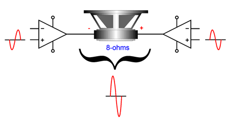
The switch offers three positions: non-inverted, mute, and inverted. We need only take the +output from the switch and send it to a single output RCA jack. Then, by rotating the switch, we chose which phase cathode follower output we wish to use. Another possible use for the Balancer is to drive two stereo amplifiers in bridge mode. What is bridge mode? Here is a long quote from my post 406:
If your stereo amplifier is tube design with an output transformer, then you get twice the wattage, not the solid-state potential of a fourfold increase. Why? The output transformer ensures a constant power output into 4, 8, and 16 ohms. In contrast, a 100W solid-state power amplifier, if it is a robust design, can deliver 200W into a 4-ohm load and only 50W into a 16-ohm load; in other words, not constant power. As far as each power amplifier in the bridge arrangement is concerned, the 8-ohm speaker is effectively a 4-ohm load, so it can deliver twice the power that each of its two amplifiers can deliver into a 4-ohm load. For example, a 100W solid-state power amplifier may only be able to deliver 160W into a 4-ohm load; thus, in bridge mode, we could only expect 320W, not 400w. In addition, I have found that bridge mode often brings a bonus in the form of reduced hum, which is usually a common-mode noise shared equally between channels. Moreover, monobloc amplifiers usually deliver better stereo imaging, as they sidestep grounding issues between channels. Well, the Balancer would be a perfect tube line-stage amplifier for bridging amplifiers—but only bridge if your speakers are 8-ohm types.
The last possible use, at least the last one that I can think of off the top of my head, is that the Balancer could be used as the frontend of a push-pull tube power amplifier. With a 12AX7 or 5751 input tube, we would easily enough gain to drive two EL34 or two KT88 output tubes to full output. Or, using the Balancer as the input amplifier, we could build a two-amplifier cascade power amplifier.
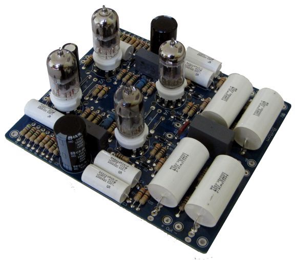
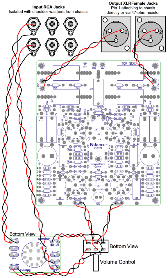
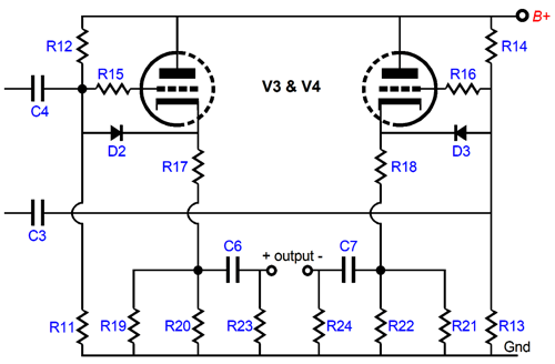
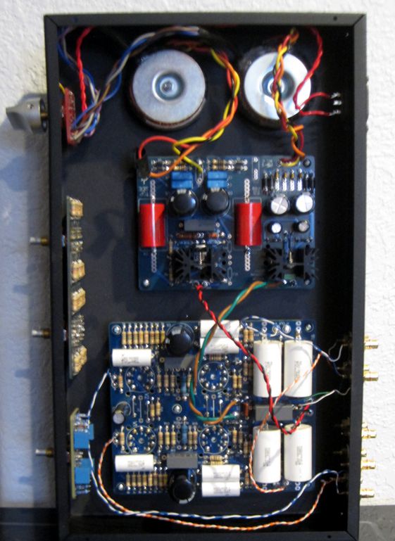
The above illustration shows how the Balancer PCB is used in a chassis. What is not shown is that we do not need to use XLR output jacks if we don't want to, as we could use four RCA jacks, two per channel. The Balancer fronted consists of a grounded-cathode amplifier input stage, followed by a split-load phase splitter. I setup the PCB so that 12DW7/ECC832 tubes could be used in the input position. In other words, we would use the 12AU7 triode inside the 12DW7 as the grounded-cathode amplifier triode and the 12AX7 triode in the phase splitter.
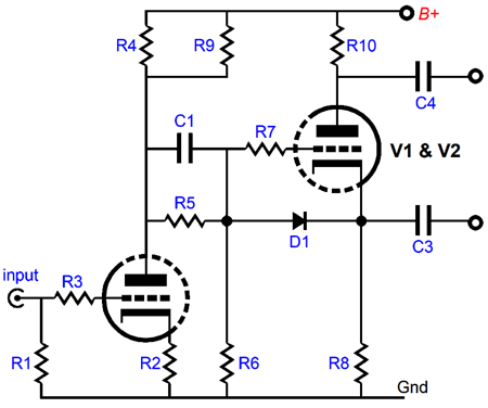
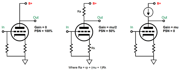
Ideally, we want the input stage to define a 50% AC voltage divider to the power-supply noise. Why? We want each of the phase splitter's outputs to hold the same amount of ripple and in the same phase. When this common-mode noise is delivered to the balanced power amplifier, the noise is largely rejected.
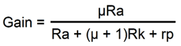
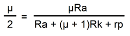
The formula for the gain of a grounded-cathode amplifier with an unbypassed cathode resistor is simple enough: We need to rearrange the formula so that the gain comes in at half of the amplification factor (mu or µ) and a PSRR of -6dB will result.
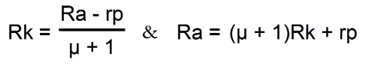
So, we start with mu/2 as the goal. Now, all we have to do is solve for Rk or Ra. The Balancer's output stage consists of two cathode followers per channel.
Note the doubled up cathode resistors. Why? These resistors get hot. For example, let's say that the triode draws 10mA of idle current and the cathode resistor value is 12k. We square the current and then divide by the resistance; which, in this example, means a dissipation of 1.2W. We could use a single 2W 12k resistor or two 1W 24k resistors in parallel.
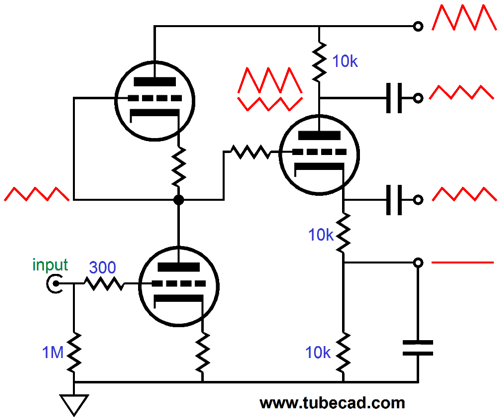
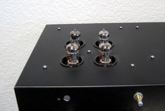
A Balancer line-stage amplifier can be built in a nearly infinite number of ways. For example, a 12AU7 or 12DW7 input tube will yield a gain of +18dB, which would prove excellent for a line stage amplifier; a 6DJ8, 6CG7, 6H30, 12AU7, 12BH7, or ECC99 as the output tube would deliver a low output impedance that could drive capacitance-laden cables. In other words, the list of useable tubes is a long one: 6AQ8, 6BC8, 6BK7, 6BQ7, 6BS8, 6DJ8, 6FQ7, 6GC7, 6H30, 6KN8, 6N1P, 12AU7, 12AX7, 12BH7, 12DJ8, 12FQ7, 5963, 5965, 6922, E188CC, ECC88, ECC99… In general, a low-mu tube works best as the input tube and a high-transconductance tube works best as an output tube. The only stipulations are that the two triodes within the envelope be similar and that the tube conforms to the 9A or 9AJ base pin-out. What about driving 600-ohm loads. It can be done, but it will require four coupling capacitors that are at least 10µF in value. In addition, the cathode follower tubes must be robust and run hard. In other words, a 12AX7 need not apply. I would use either a 6DJ8 or 6H30 or 12BH7 or ECC99 in the output position. In addition, I would use 470µF 250V RC filter capacitors and a 160Vdc to 200Vdc B+ voltage, with each cathode-follower triode idling at least 10mA. So, how does this new circuit sound? I had fairly low expectations, as the four output coupling capacitors were smaller CDE 940 series, not the bigger and better-sounding 942 series that I now carry. In addition, the two B+ RC filters, one filter per channel, do not use pure polypropylene capacitors as the new Aikido PCBs do. Moreover, I have not finished assembling the chassis. (I soldered the tube sockets on the PCB topside and all the other parts were soldered to the bottom of the PCB, so I could have the tubes protrude from the chassis top.) Nonetheless, I thought the Balancer sounded great. I used 12AU7 tubes throughout (a mix of old NOS and new) and the gain was more than sufficient. The B+ voltage leaving the PS-1 regulator was 260Vdc, with 12Vdc for the heaters. (I like running slightly less heater voltage, as it prolongs tube life.) I loved being able to flip the phase of the output signal. Interestingly, the simpler the arrangement of musicians and singers, the easier it was hear the difference flipping the phase made. (Check out my music recommendation for this post.) I am waiting for a shipment of the CDE 942 series capacitors to arrive. Once they do, I will eagerly solder in four of them and give the Balancer another extended listen.
The new GlassWare Balancer PCB and kit are available now at the GlassWare-Yahoo store.
More Class-G
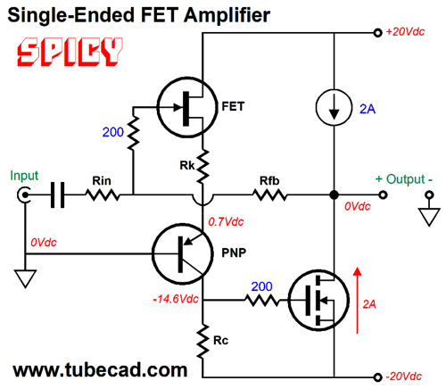
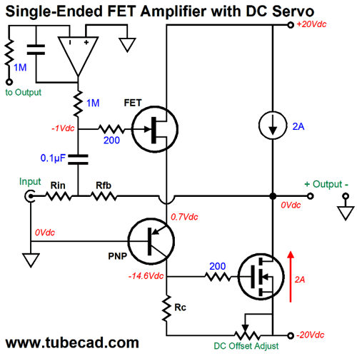
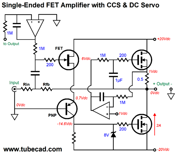
Ready for this, I have even dreamt of class-G topologies one night; and the dream was close to a nightmare, similar to dreaming of being trapped in a large building, such as a hospital or government office or university, and not being able to find a useable exist. When I awoke from troubled sleep, I fired up SPICE and quickly ran simulations on the solution that had appeared in my dream. It worked! This is rare, as most dream-inspired circuits fail to work. Recently, my obsession has been with single-ended class-G output stages, which many would dismiss as impossible. In contrast, push-pull class-G output stages are easy. Well, once again, we will begin at simple and end at complex. The following schematic shows a class-A, single-ended amplifier that uses a bipolar power supply and no output coupling capacitor. This amplifier inverts the input signal phase at its output and a negative feedback loop sets the gain and reduces the distortion and output impedance, while limiting the DC offset at the output.
The 2A constant-current source sets the idle current through the single output MOSFET and establishes a potential output power of 16W into an 8-ohm load impedance. The PNP transistor cascodes the input FET in a bastode fashion. This amplifier works well in SPICE, but would prove difficult in reality, as the output stage is not likely to center a 0V for long or at all. One workaround would be to add a potentiometer to adjust the DC offset.
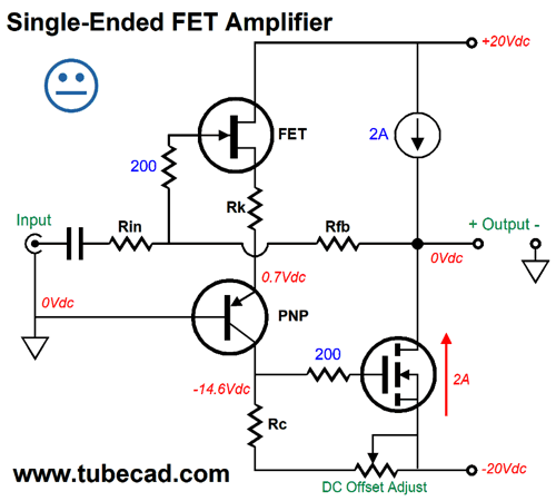
In all all honesty, I would rather add an output coupling capacitor, as the DC offset could vary with the ambient temperature. By the way, making a high-current constant-current source out of a P-channel MOSFET is easy enough.
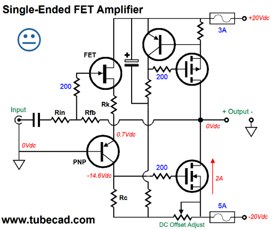
Note how the output does not slam to one rail voltage if one fuse opens. In contrast, the following arrangement will cause a positive slam, if the bottom fuse blows.
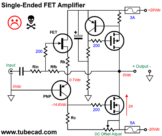
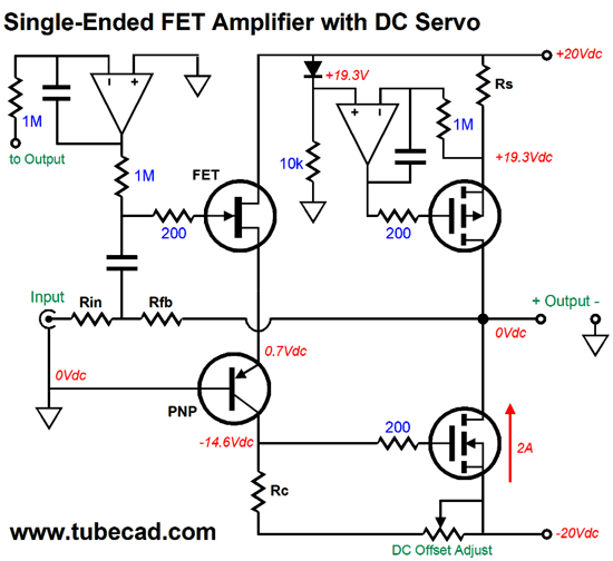
Note how the negative power-supply-rail fuse blowing does not stop the constant-current source from drawing 2A of current, which would pull the output up 16Vdc. The best workaround, however, would be to add a DC servo circuit that would constantly strive to eliminate the DC offset.
Note how the input coupling capacitor is rearranged. Even if the signal source presents its own DC offset, this arrangement blocks it and still maintains a 0V output at idle. Also note how we lost the resistor between the FET and PNP transistor, which results in greater gain and, thus, more negative feedback. Since dual-amplifier OpAmps are common, we could a second OpAmp to create the constant-current source.
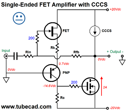
Another possible workaround is to replace the constant-current source with a compliant-constant-current source (CCCS), which hold force the output to close to 0V intrinsically.
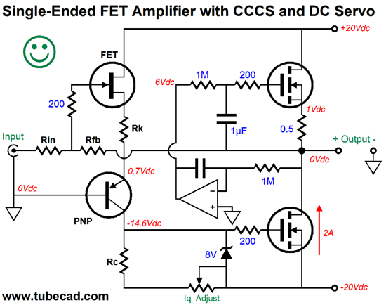
The way the CCCS does this is by being referenced to ground to start with, so the potentiometer has a smaller range of offset voltage to deal with. Of course, we could add a DC servo to the CCCS.
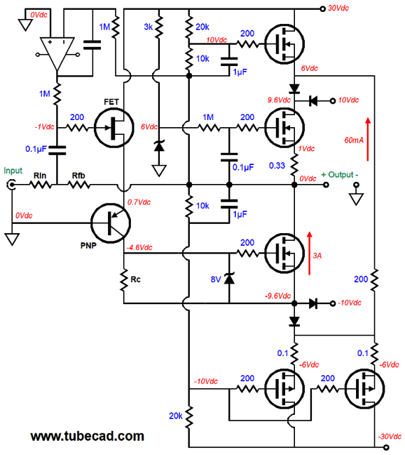
We can even get extra fancy and use two OpAmps, one to set the idle current and the other to eliminate the DC offset.
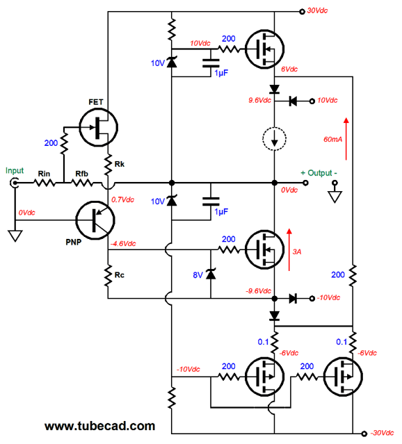
Now, it's time to add class-G to the output stage. In order to prevent clutter, I will leave out the DC servo circuits of the following schematic.
Note the +/-10V power-supply rail voltages and the idle current of 3A. In addition, the amplifier now holds three extra power MOSFETs and four ultra-fast rectifiers. The CCCS MOSFET gets one power-supply cascoded MOSFET. In contrast, the bottom output MOSFET gets two power-supply cascoded power MOSFETs. All three of these cascoded MOSFETs never turn off, as the 200-ohm resistor that bridges the two sources provides a current path between the two outer MOSFETs. This resistor is my own workaround to the problem that many class-G output stage face, namely the harsh switching on and off of the cascode devices, which can provoke local oscillations. Okay, let's look at the fleshed out design.
At idle, the two inside MOSFETs dissipate 30W each, while the two outside MOSFETs only dissipate about 1.5W each. Of course, when the amplifier output swing sufficiently to engage the outer MOSFETs, they will become plenty hot, as the top MOSFET's current conduction will slam from 60mA to 3A, while the bottom cascode MOSFET will go from 60mA to 4A and then see 6Apk at full output, which explains why two MOSFETs are used in the bottom cascode position. The maximum power out into an 8-ohm load is equal I² x Rload/2, or 36W in this example.
Tubes Enter the Schematic
Note, the class-AB or class-B limitation in Slone's definition. Why not class-A output stages. Heck, why not a class-G single-ended power amplifier? As you can imagine, such questions send me off to find my drawing tablet and mechanical pencil. After sketching several single-ended output stages that used power triodes and a class-G configuration, I soon realized that the triode was a poor choice. Why? The triode's current flow is sensitive to its cathode-to-plate voltage, as the triode exhibits plate resistance (rp). In other words, a triode's plate is 1/mu as effective as its grid in controlling current flow through the triode. In a class-G setup, the B+ voltage remains fixed at idle and at low levels of output voltage swing. Once the output voltage swings beyond a threshold voltage, the B+ voltage rises with the output signal. Well, where this abrupt change in B+ voltage occurs creates a glitch in the output waveform. In contrast, transistor, MOSFETs, and pentode are far less sensitive to changes in B+ voltage. Before showing you a pentode-based class-G single-ended output stage, let look at a one based on MOSFETs, as it is less cluttered.
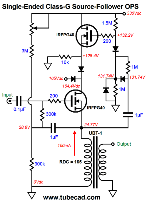
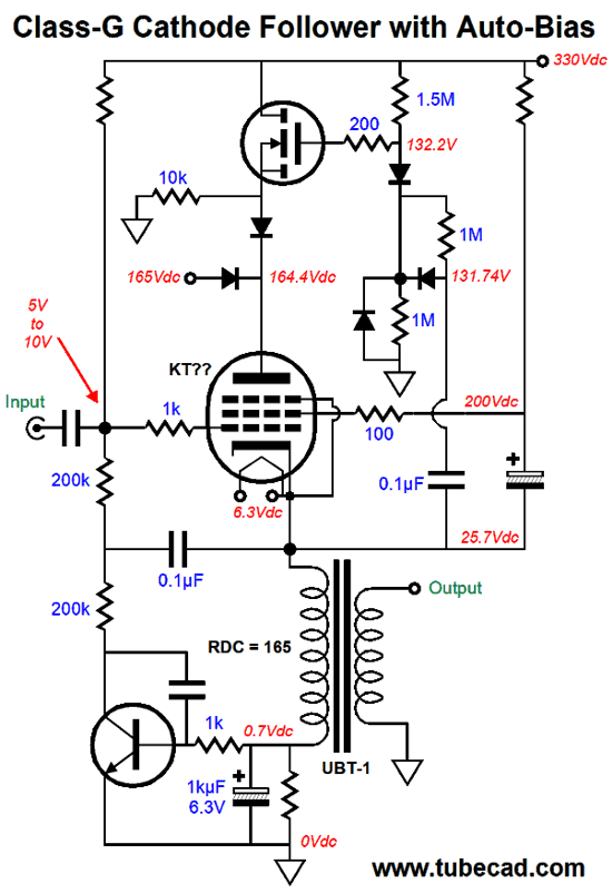
An output transformer is used and two power-supply rail voltages are used: 165Vdc and 330Vdc. These voltages are easily obtained by using a center-tap 240Vac secondary. The commutating diodes are not marked, but I was thinking of MUR420G diodes. (With a reverse breakdown voltage of only 200V, they may not be the best choice. Many faster, as in less 20ns, rectifiers with higher breakdown voltage are available, but they usually exhibit a larger voltage drop, which shouldn't be a concern in this design.) At idle, only the bottom MOSFET draws much current and dissipates most heat; 150mA and 20.9W versus 6.77mA and 1.8W. If this were not a class-G design, the MOSFET would have to dissipate 46W of heat. The output stage is configured as a source follower, which offers no signal voltage gain. The idle current of 150mA implies a peak potential power output of 18W, as i² x Rload/2 equals the AC power output. The UBT-1's primary impedance is 1600 ohms. The UBT-1's secondary DC resistance (DCR) is used to set the idle current through the bottom MOSFET, as the DCR functions as source resistor. An idle current of 150mA against the 165-ohm DCR equals a voltage drop of 24.75V, which in the schematic is rounded up to 25V. The UBT-1's winding ratio between primary and the secondary's 8-ohm tap to ground is 14.14, so for every 14V of primary voltage swing, the 8-ohm loudspeaker sees 1V of voltage swing. The two-resistor voltage divider made up of the 1.5M and 1M resistors impose a bias voltage of 131.74V across the coupling capacitor that feeds the top MOSFET's gate. The 1µF capacitor that bridges the primary to the two 300k resistors is there to unload the signal source and to prevent power-supply noise from leaking into the output stage's input. When the bottom MOSFET's source swings up by about 30V, the top MOSFET's source couples to the bottom MOSFET's drain through the top diode, and the bottom MOSFET sees its drain voltage climb; in addition, both top and bottom MOSFET will share the same current flow through the output transformer's primary and the top MOSFET will get much warmer. As the input signal, which must be huge, as in +/-265Vpk, the top MOSFET's source voltage will fall below the top diode's turn-on voltage and the bottom's MOSFET's drain will once again see a fixed voltage of 164.4Vdc. Most MOSFET exhibit a maximum source-to-gate voltage of +/-20V, which we never want to exceed. During the negative swings, however, we might. Thus, the extra three diodes at the 1µF coupling capacitor. When the bottom MOSFET's source swings up, one diode becomes forward biased and conducts, which then pulls up the top MOSFET's gate voltage. But when the top of the 1µF capacitor swings below the voltage needed to keep the diode that attaches to the coupling capacitor forward biased, the diode ceases to conduct, leaving only the 1M shunting resistor to connect the coupling capacitor to the top MOSFET's gate circuit, and the top MOSFET's gate sees a 33Vdc minimum voltage. (This workaround came to me in that troubled dream.) The diode that shunts the 1M that terminates into ground is there as an added safety feature, as it imposes a hard limit to the peak negative gate-voltage swing. Inductive loads and solid-state devices are a dangerous pairing, as the inductance can provoke huge high-voltage spikes, say when the amplifier is playing and the speaker cable breaks contact momentarily. In other words, we can never have too many safety features. I ran some SPICE simulation on the circuit shown above and I was impressed.
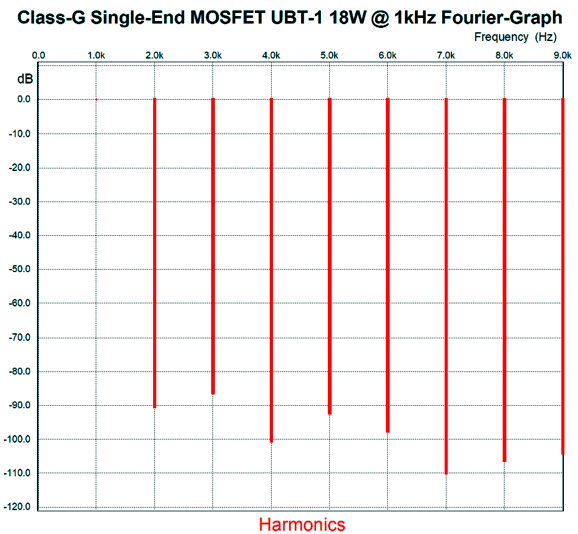
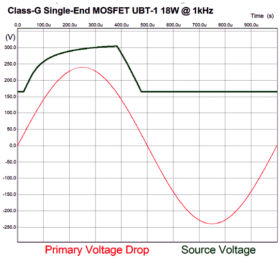
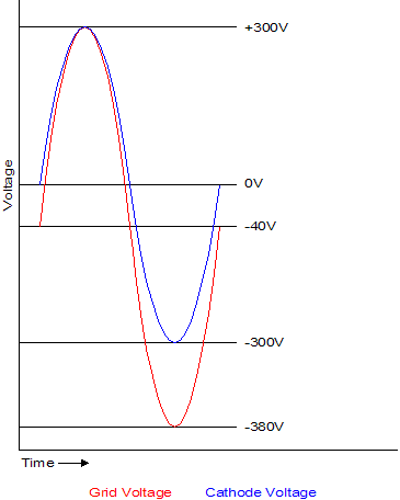
The graph shown above was SPICE generated with IRFPG40 MOSFET models. The THD at full power in the simulation came in below 0.01%. If this were not merely a stepping-stone to a tube-MOSFET hybrid, I would alter the power-supply-rail voltages, as we could shave 50V off the 330Vdc B+ voltage and lower the second power-supply voltage to something closer to 140Vdc. Here is a graph of the voltage relationships at full output. (The primary's RDC was not included in this graph, but was included in the simulation.)
It's time, however, to switch over to the pentode-based version.
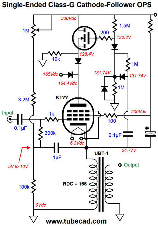
The output tube could be anything from a KT88 to a KT150, as any of these could withstand the 21W of dissipation at idle. The pentode is run as a pentode, not a triode-connected pentode or in ultra-linear mode. While the UBT-1 primary DCR could be used to set the idle current with a different output tube or a triode-connected pentode, its value is too high in this application, so we must apply a positive bias voltage to the pentode's grid. The 1M potentiometer is used to set the idle current. Much like the all-MOSFET version, a huge input signal is needed to drive the output stage to full output, say far more than the +/-265Vpk the all-MOSFET version required, as the pentode exhibits far lower transconductance than the MOSFET.
Note that when the top of the internal coupling capacitor swings above the 330V B+ voltage, the topmost diode is no longer forward biased and the top MOSFET's gate sees a maximum of the 330V B+ voltage. Since this output stage is basically a cathode follower type, it requires a huge input signal.
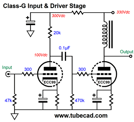
As you can see from the example above, it takes +/-340Vpk to get +/-300Vpk out of the cathode follower's cathode. With the 1600-ohm UBT-1 and the 150mA idle current, we only need +/-265Vpk of cathode voltage swing, so the pentode's grid must see a much bigger voltage swing. The following schematic shows one possible input and driver stage.
The ECC99 exhibits an amplification factor of 22, which just might prove sufficient. Ideally, we want to amplify 1Vpk of input signal to about 290Vpk. If we don't get enough voltage swing, the solution is to run a higher B+ voltage for the driver stage.
Class-S Amplifiers
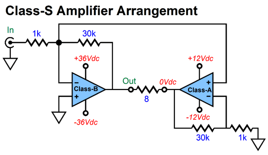
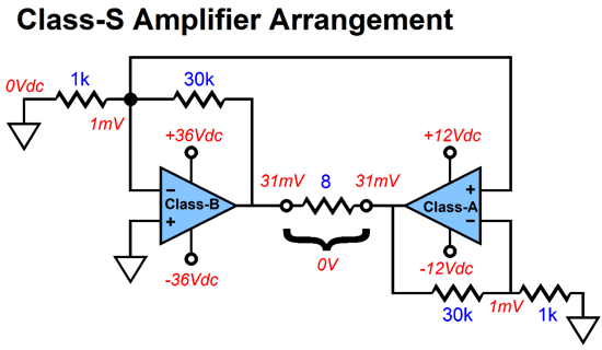
The dirty class-B amplifier delivers big watts, while the clean class-A amplifier functions as a virtual ground, but with a difference: the difference is that there is no difference, as far as the class-B amplifier's distortion is concerned, as the class-A presents the exact same distortion in phase at the class-A amplifier's output. In order to illustrate this point, let's use a DC offset on the class-B amplifier's output as a form of distortion, which it is, as it is a deviation from the input signal.
Note how the class-A amplifier must sink and source all the current that will flow through the loudspeaker. In the example above, however, no current flows through the speaker. How much current must flow through the class-A amplifier at idle? Let's assume that the class-B amplifier can swing +/-32Vpk of output signal, which implies 64W of output power and 4Apk of output current into an 8-ohm load. If the class-A amplifier holds a push-pull output stage, then its idle current should be at least 2A. Now, let's assume that the class-A can put out +/-10V peak voltage swings, which means that the complete class-S amplifier can actually swing closer to 40Vpk of voltage. How so? When the class-B amplifier clips, the class-A amplifier still gets an input signal and its output takes over where the class-B amplifier left off, so we end up with 10 volts more of output swing, for something closer to 100W of power.
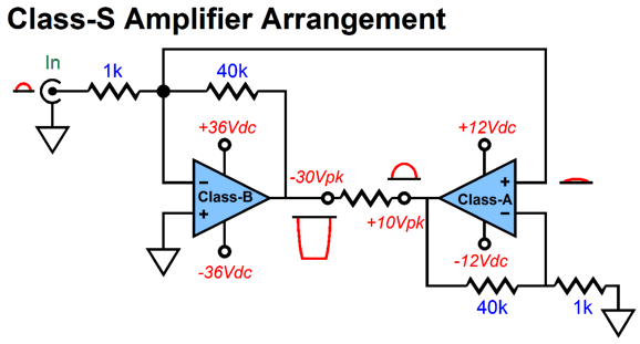
Since the true peak current swing is equal to 40V/8 or 5A, the class-A amplifier's output stage should idle at least 2.5A. There is only one problem: it would better if the class-B amplifier didn't clip, as amplifiers often clip in a nasty way and the output stage becomes "sticky." My workaround is the following.
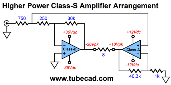
Note that 1/4th of the input signal is now sent to the class-A amplifier. In other words, the class-A amplifier no longer functions as pseudo ground, as its output now traces the input signal. It will still, nevertheless, largely erase the class-B amplifier's distortion. Full erasure would require a gain of 41.333... from the class-A amplifier. The closest 1% resistor value to 40,333 is 40.2k. Well, we could place this 40.2k resistor in series with a 133-ohm resistor to get closer to the optimal value. Furthermore, both amplifiers will now clip at the same time, when called upon to put out more than 40Vpk into the loudspeaker.
Music Recommendation: Musica Nuda
Tidal offers the above three albums (there might be more, as you can never be too certain with Tidal). Do give them a listen, before Tidal drops them, as they apparently have on some of their other albums. Much like Netflix, Tidal churns its selections. //JRB
If you enjoyed reading this post from me, then you might consider becoming one of my patrons at Patreon.com
User Guides for GlassWare Software
For those of you who still have old computers running Windows XP (32-bit) or any other Windows 32-bit OS, I have setup the download availability of my old old standards: Tube CAD, SE Amp CAD, and Audio Gadgets. The downloads are at the GlassWare-Yahoo store and the price is only $9.95 for each program. http://glass-ware.stores.yahoo.net/adsoffromgla.html So many have asked that I had to do it. WARNING: THESE THREE PROGRAMS WILL NOT RUN UNDER VISTA 64-Bit or WINDOWS 7 & 8 or any other 64-bit OS. I do plan on remaking all of these programs into 64-bit versions, but it will be a huge ordeal, as programming requires vast chunks of noise-free time, something very rare with children running about. Ideally, I would love to come out with versions that run on iPads and Android-OS tablets. //JRB |
John Gives
Special Thanks to the Special 71
I am truly stunned and appreciative of their support. In addition I want to thank
All of your support makes a big difference. I would love to arrive at the point where creating my posts was my top priority of the day, not something that I have to steal time from other obligations to do. The more support I get, the higher up these posts move up in deserving attention. Only those who have produced a technical white paper or written an article on electronics know just how much time and effort is required to produce one of my posts, as novel circuits must be created, SPICE simulations must be run, schematics must be drawn, and thousands of words must be written.
If you have been reading my posts, you know that my lifetime goal is reaching post number one thousand. I have 552 more to go. My second goal is to gather 1,000 patrons. I have 929 patrons to go. Help me get there.
Support the Tube CAD Journal & get an extremely powerful push-pull tube-amplifier simulator for TCJ Push-Pull Calculator
TCJ PPC Version 2 Improvements Rebuilt simulation engine *User definable
Download or CD ROM For more information, please visit our Web site : To purchase, please visit our Yahoo Store: |
|||


| www.tubecad.com Copyright © 1999-2018 GlassWare All Rights Reserved |