| John Broskie's Guide to Tube Circuit Analysis & Design |
28 February 2019 Post Number 457
Another How-To Example
The constant-current-draw amplifier (CCDA) topology is a good candidate, as it offers gain and a low output impedance and does not bang the power-supply rail about, as total current flow remains fairly constant. as the input grounded-cathode amplifier and the output cathode follower current-flow variations cancel, being in in voltage phase but in anti-current phase. The CCDA does, however, invert the input signal phase and it suffers from Miller-effect input capacitance magnification. Phase inversion is no big deal in a line-stage amplifier, as we need only flip the loudspeaker wires, as two inversions equal no inversion. The higher input capacitance, however, can prove to be problem, if the volume control presents too high an output impedance. In addition, the CCDA offers a PSRR of only -6dB.
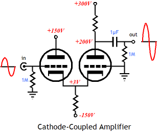
In contrast, the cathode-coupled amplifier offers no phase inversion and low input capacitance. Its output impedance, however, is high and its PSRR figure is also not great; with a constant-current source loading the coupled cathodes, the PSRR approaches zero. Well, that's true of the textbook cathode-coupled amplifier, not my Aikido version.
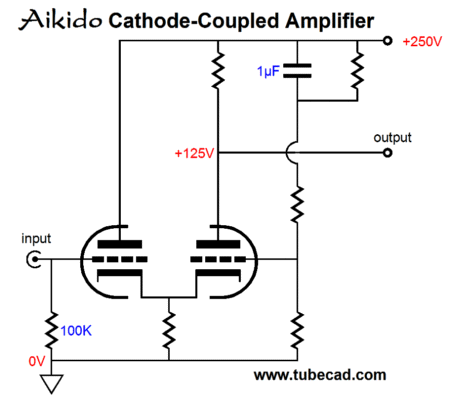
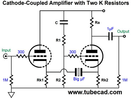
Note how the right triode's grid is simply grounded. In contrast, the Aikido cathode-coupled amplifier uses the right triode grid to purposely inject a small portion of the power-supply noise to prompt a power-supply-noise null at the output.
Note how the right triode's grid not only sees the AC signal of the sampling of the power-supply noise, but a small positive DC offset voltage. This offset voltage is needed to compensate for the the two triodes seeing different cathode-to-plate voltages. If both triode are going to draw the idle current, but run under different cathode-to-plate voltages, then they must see different grid DC voltages.
Another workaround to this problem of dissimilar voltages is the following.
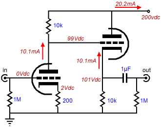
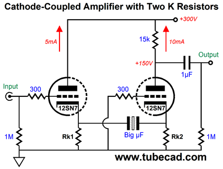
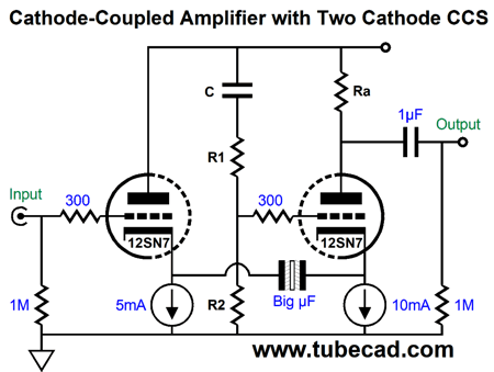
Note that no DC offset appears at either grid, as both see the same 0Vdc. Also note how the two cathode resistors and large-valued internal coupling capacitor solve the dissimilar cathode-to-plate voltages problem. The assumption here is that non-polarized electrolytic capacitor will be used to couple the the two cathodes. Here is where the how-to enters the picture. How can we find the right parts values? As you probably already guessed, I do not recommend that you machine-gun your way to the answers, as there simply to many variables. So, where do we start? We start with that which cannot be changed and that which is desired. For example, let us say that we have a serviceable power supply that puts a fairly clean 300Vdc and is good for 40mA of current flow; this will become are first two unchangeable variables: the B+ voltage and the maximum total idle current. Next, what do we desire? For a line-stage amplifier, we do not need a lot of gain, but we do want it to be as quiet as possible, so high-mu or low-gm triodes are out. A good choice for a dual triode tube would be a 6CG7, 6H30, 6SN7, 12AU7, 12BH7, 12SN7, 12SX7, 5687, or ECC99. I would prefer a 12V heater, as it is easier to create a 12Vdc regulator than a 6.3Vdc regulator, as we lose a lower percentage of voltage to rectifier losses. Since I have so many 12SN7 tubes, that will be my choice. In addition, the 6H30 and 5687 and ECC99 should be run under a heavier idle current per triode, say at least 10mA, which could bring the total idle current over the 40mA limit. In contrast, the 12SN7 works well with only 5mA per triode and even better with 10mA of current flow.
Now that we know the B+ voltage, the idle current, and the tube used. What's left is all the part values. Since the grounded-cathode amplifier portion of the cathode-coupled amplifier, i.e. the right triode and plate resistor, must drive the interconnect to the power amplifier, its idle current should be as robust as possible. Considering the 40mA power-supply current limit, lets set its idle to 10mA and set the cathode follower portion of the cathode-coupled amplifier, i.e. the left triode and cathode resistor, to 5mA, which would bring the current flow per channel to 15mA and the total current flow of the line-stage amplifier to 30mA. The next question is, How to we find the plate resistor value? This question leads to the question, What plate voltage do we want for the right triode? Possible candidates are 100V, 150V, 200V, and 250V, although in reality an infinite array of voltages between 100V and 250V are possible. I choose to match the plate dissipation of the input triode, which sees 300V against an idle current of 5mA, making for 1.5W of plate dissipation, so the right triode should see 1.5W divided by 10mA, resulting in a plate voltage of 150V. With the plate set to 150V, we also know that the plate resistor value is 15k, as (300V - 150V)/0.01 = 15,000.
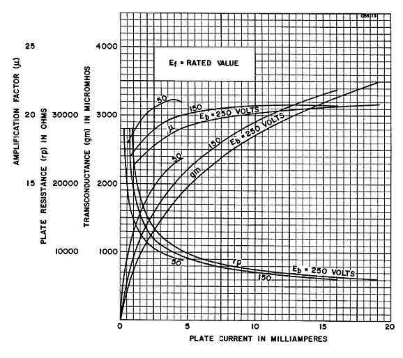
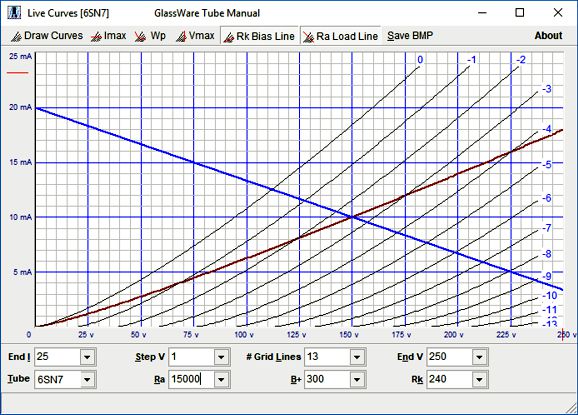
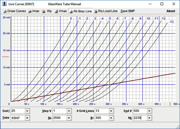
We move on to finding the two cathode resistor values. Four ways exist to find the required cathode voltage to set the desired idle current under a given cathode-to-plate voltage with the grid grounded. (Well, many more ways actually exist, such as wild guessing or divine revelation or emailing me, the last of which is the least desirable way—for me at least;) The first is to fire up the high-voltage regulator and test the circuit on our workbench, which we wish to avoid, at least at the start; after the circuit is actually assembled in reality, reality will pass judgment and we will make what amends are needed. The second way is to use math. The formula for the needed cathode voltage is Vk = (Vp - rp·Iq) / (mu + 1) The third way is to inspect the published plate curves for the 6SN7. We find the intersection of 150V and 10mA, and then the intersection of 300V and 5mA. The next step is to guess the grid voltage, as it is unlikely that a grid-voltage plot-line will hit either intersection.
As the grid voltage increases in negative voltage, we must subtract this voltage from the plate voltage. For example, the true intersection for the 300V value is at 300V - 11V and 5mA.
The forth way is to use SPICE. SPICE is wonderful, but it presents many traps. One of which is that the triode models are not that good. See post 48 and you will see how off the SPICE model of the 6SN7 is when compared to the tube manual plate curves and curve tracer plot lines (no, I did not repeat myself) and to my own, True Curves™, triode math model. Nonetheless, we are only try to dang close to the real value, so SPICE is probably the quickest way to good guesstimate answer.
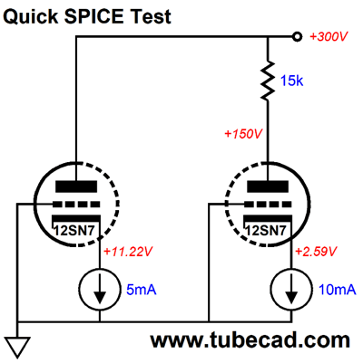
Two 6SN7 triodes are tested at 5mA and 10mA idle currents, as that is what the two constant-current sources force on the triodes.
After running these values in SPICE, we get these voltage values. To find the value of Rk1 we take 11.22Vdc and divide 0.005A to find the resistance of 2244 ohms; next, we divide 259V by 10mA and get 259 ohms. I decided to use the nearest 5% resistor value and rounded up to Rk1 = 2.3k and Rk2 = 270 ohms.
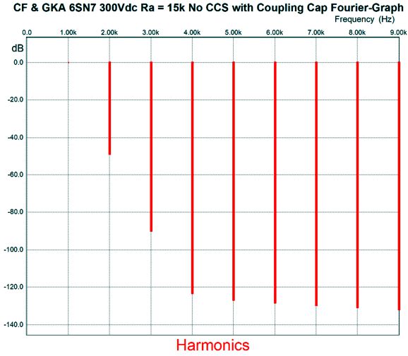
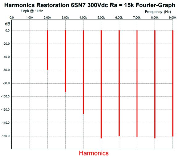
Close enough for government work. All that is left is to find the optimal values for the Aikido voltage divider values (R1 and R2). A good starting guess would be that R1 is mu times larger than R2. Now, we must machine-gun are way to the deepest power-supply noise null at the output. In SPICE simulations, 200k and 10k provided too little power-supply noise, as the noise wasn't inverted at the output; in other words, we under compensated. I then tried 180k and 10k and found that the power-supply noise at the output was inverted, so not too much compensation. I then split the difference and used 190k and 10k; too much compensation. Finally, I arrived at 191k and 10k. of course, reality may prefer a slightly different ratio, but we will be close. In SPICE simulations, the gain came i at 5 (+14dB) and the PSRR was -47dB, while the output impedance was 5.7k. Here is the SPICE-generated Fourier breakdown of harmonics of 1Vpk at 1kHz.
This translates in a THD of 0.37%, which is much higher than I expected, to be honest. Using constant-current sources would improve the THD substantially, but they would work against my goal of simplicity; in addition, they would result in more gain.
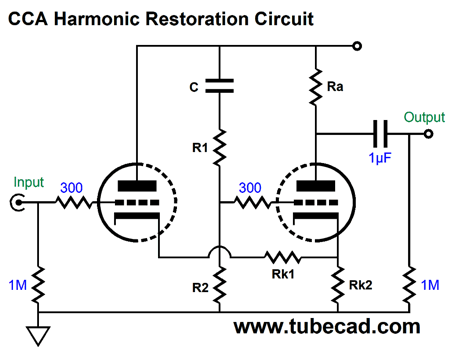
Harmonic Restoration Version
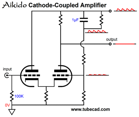
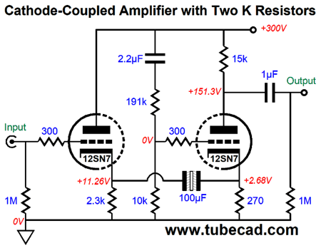
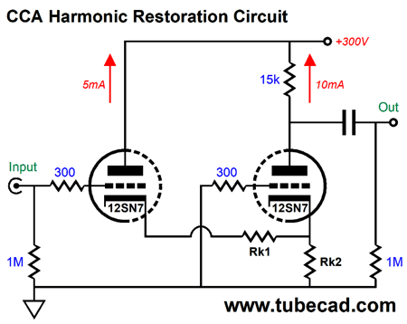
Note how cathode resistors Rk1 and Rk2 define a two-resistor voltage divider. In other words, the grounded-grid amplifier portion of the cathode-coupled amplifier will only see a portion of the input signal's magnitude. (If cathode resistor Rk2 were replaced by a constant-current source, then no voltage division would obtain.) Let's use the same idle currents and the same plate resistor value as before.
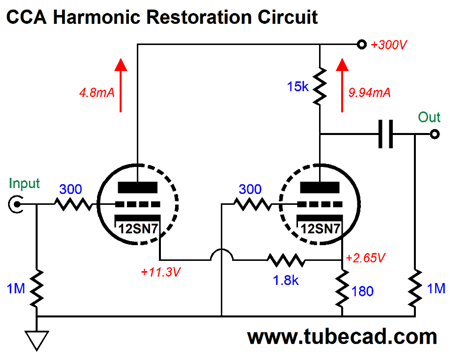
To find the value of Rk1, once again, we take 11.22Vdc and subtract 2.59V, leaving 8.63Vdc. Next, we divide 8.63V by 5mA to find the resistance of 1726. Since cathode resistor Rk2 sees the combined current flow from both triodes, we divide 2.59V by 15mA and get 173 ohms. I decided to use the nearest 5% resistor value and rounded up to Rk1 = 1.8k and Rk2 = 180 ohms. After running these values in SPICE, we get these voltage values.
The gain comes in close to unity, being 1.03, which is dang close to unity. The output impedance is 7.2k. The PSRR was -48dB. Here is the Fourier breakdown of harmonics of a 1Vpk @ 1kHz.
The THD was a surprisingly low 0.11%. So much for harmonic restoration.
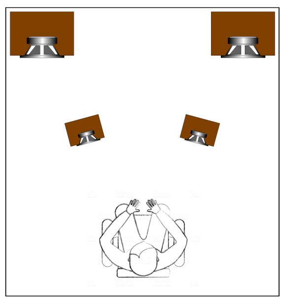
HeadWoofer Question In contrast, where I do think that a bit of time delay would certainly help is when the subwoofers are placed in the corners. Everyone knows that corner placement result in massive bass, as the corners act like horns and give the subwoofers an easier time grabbing hold of the air. In contrast, when placed out in the room, the air—at extremely low frequencies—tends to just move sideways away from the woofer cone, resulting in less of a grip. In the conner, the air is trapped, however, so more grip.
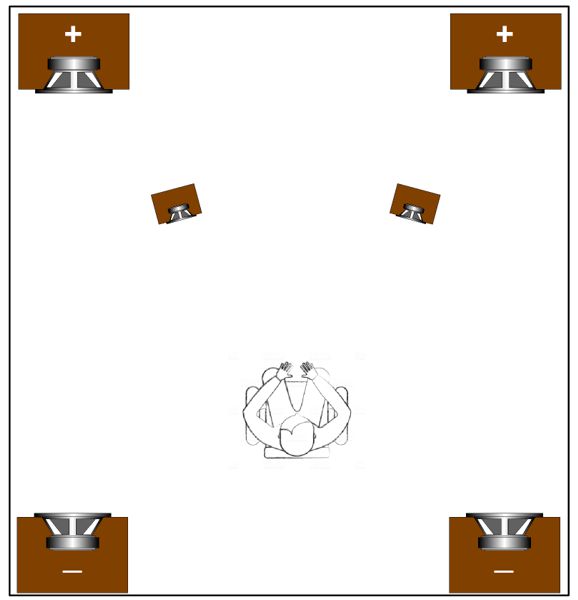
The front subwoofers are in phase with the primary speakers, but should be time advanced, so that the subwoofers and primary speakers line up in time. In other words, the primary speakers must be delayed so front subwoofers can get their signal before the primary speakers. Another interesting possibility is to use four subwoofers and time delay.
The rear subwoofers are there to add to the front subwoofer's output. Instead, they are run in anti-phase and attenuated and time delayed. Why? When the front subwoofer's output hits the rear wall can only cause problems. Ideally, we wouldn't have a rear wall. With the rear subwoofers running in inverted mode and time delayed, the front woofer's output will be largely nulled at the rear wall.
Music Recommendation: MOKAVE Volume 2 Tidal offers this album and two others by the trio (Glen Moore, Glen Velez, Larry Karush), both of which also appear to be on the Audioquest label.
//JRB
If you enjoyed reading this post from me, then you might consider becoming one of my patrons at Patreon.com
User Guides for GlassWare Software
For those of you who still have old computers running Windows XP (32-bit) or any other Windows 32-bit OS, I have setup the download availability of my old old standards: Tube CAD, SE Amp CAD, and Audio Gadgets. The downloads are at the GlassWare-Yahoo store and the price is only $9.95 for each program. http://glass-ware.stores.yahoo.net/adsoffromgla.html So many have asked that I had to do it. WARNING: THESE THREE PROGRAMS WILL NOT RUN UNDER VISTA 64-Bit or WINDOWS 7 & 8 or any other 64-bit OS. I do plan on remaking all of these programs into 64-bit versions, but it will be a huge ordeal, as programming requires vast chunks of noise-free time, something very rare with children running about. Ideally, I would love to come out with versions that run on iPads and Android-OS tablets. //JRB |
John Gives
Special Thanks to the Special 74
I am truly stunned and appreciative of their support. In addition I want to thank the following patrons:
All of your support makes a big difference. I would love to arrive at the point where creating my posts was my top priority of the day, not something that I have to steal time from other obligations to do. The more support I get, the higher up these posts move up in deserving attention.
If you have been reading my posts, you know that my lifetime goal is reaching post number one thousand. I have 546 more to go. My second goal is to gather 1,000 patrons. I have 926 patrons to go. Help me get there.
Support the Tube CAD Journal & get an extremely powerful push-pull tube-amplifier simulator for TCJ Push-Pull Calculator
TCJ PPC Version 2 Improvements Rebuilt simulation engine *User definable
Download or CD ROM For more information, please visit our Web site : To purchase, please visit our Yahoo Store: |
|||


| www.tubecad.com Copyright © 1999-2019 GlassWare All Rights Reserved |