| John Broskie's Guide to Tube Circuit Analysis & Design |
|
08 March 2019 Post 458
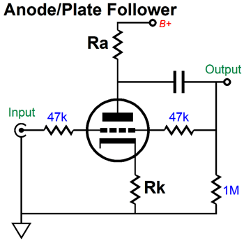
Anode Follower Circuits
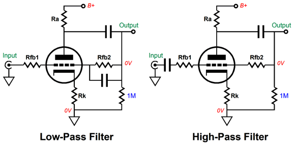
Negative feedback offers many features, such as lower THD, lower output impedance, improved PSRR, and consistency. Consistency, like so many other virtues, is seldom mentioned these days. Tubes age. Tubes differ in specifications, between brands and between years of manufacture. External load impedances vary. But with the application negative feedback, these variations diminish in consequence. In addition, the negative feedback loop allows us to set the gain and to apply frequency filtering.
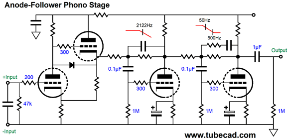
In fact, we can perform the required inverse RIAA equalization curve for a phono preamp by using two anode followers in series.
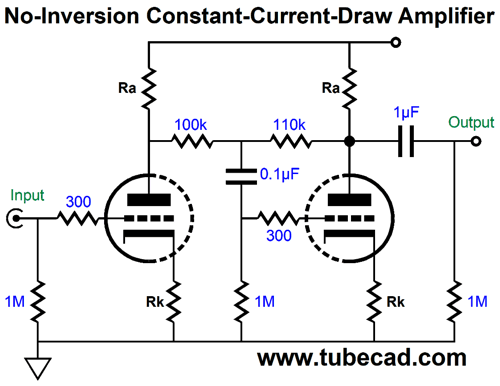
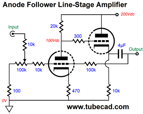
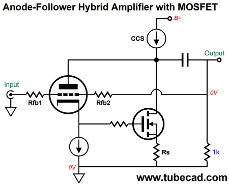
This phono preamp holds three cascading gain stages. The one in the middle sets the 75µs low-pass filter, while the last imposes the bass lift between 50Hz and 500Hz. If we left the last stage off, we could use the phono preamp to rip LPs and let software do the 3180µs and 318µs bass boost. In this design, I would use the fourth triode as a cathode follower inside the anode follower. Like the grounded-cathode amplifier, the anode follower inverts the input signal at its output, which is neither good or bad in any absolute sense. In fact, we can create constant-current-draw amplifier by cascading a grounded-cathode amplifier into an anode follower, as shown below.
The input stage, the grounded-cathode amplifier, provides the gain and the anode follower delivers the low output impedance—and phase inversion, which makes the entire amplifier non-inverting. If the second stage provided far more gain, the two negative feedback resistors would share the same value. Since both stages see the same current swings, but in anti-phase, the net current draw remains constant. Constant-current-draw is great feature in an audio circuit, as it greatly unloads the power supply; moreover, it prevents audio signals from circulating through the power supply. Another use for a second triode is as a cathode follower, which will offer a far lower output impedance.
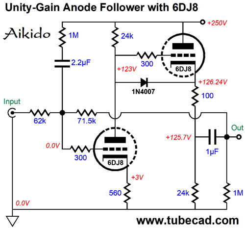
The circuit shown above offer gain and uses a linear potentiometer as a volume control. Check out my post 425 for more details on this variation. Next, we see a unity-gain version.
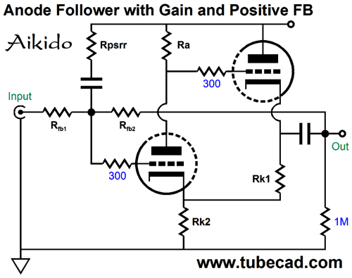
As you can readily see, this circuit is a CCDA amplifier with a negative feedback loop. I added some Aikido mojo with 1M resistor and 2.2µF capacitor. We can get fancier still, as we can add some positive feedback.
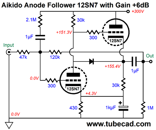
Note that cathode resistor Rk1 does not terminate into ground, but into the input triode's cathode, which results in positive feedback, which in turn increases the open-loop gain. On the other hand, we can bypass Rk2, which will undo the AC positive feedback effect.
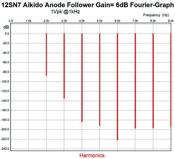
So, why bother with this arrangement? The 1kµF bypass capacitor is greatly unloaded, as it doesn't have to shunt any AC current. The feedback resistors set a gain of 2 or +6dB. Here is the SPICE-generated Fourier graph for this circuit.
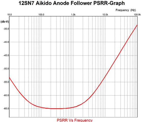
The THD is 0.0%. Not bad. Here is the PSRR graph.
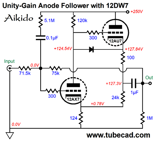
Very fine indeed. Do not worry too much about the reduction of PSRR at high frequencies, as the B+ shunting capacitors will take effect and flatten the right-half of the graph. The key band of frequencies to look at is from 100Hz to 120Hz, as that is where the B+ ripple will peak. The two triodes do not have to be the same type. The following unity-gain anode follower uses a 12DW7/ECC832 tube, which holds a 12AX7 triode and 12AU7 triode.
In SPICE simulations, this circuit yielded insanely low distortion, so much so that I won't show the graph, as it would prove too unbelievable. Still, if reality is ten times worse, we would still have an amazing performer.
Anode Follower SRPP
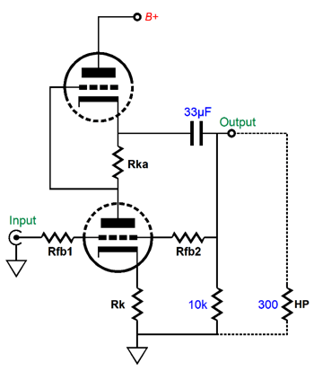
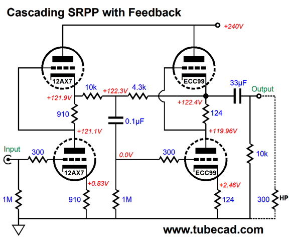
The SRPP, unlike the cathode follower, must be tuned to (optimized to) a specified load impedance. Adding the negative feedback loop helps overcome this SRPP limitation. The bottom cathode resistor can be bypassed by a large-valued capacitor if needed. We can drive the SRPP's input feedback resistor with another SRPP.
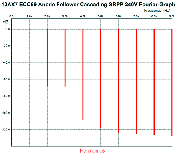
The 12AX7 is high-mu, low-transconductance triode that seldom works well in an SRPP topology, but not this time. It has been optimally configured to drive the 10k input feedback resistor, just as the second SRPP has been optimized to drive 300-ohm headphones. Note that the negative feedback resistors reduce the output SRPP's output to less than unity gain. In other words, the 12AX7's high gain is burned off driving the anode follower's feedback loop. All in all, this is not your typical gratuitous SRPP. In SPICE simulations, this circuit worked quite well, as revealed by the following Fourier graph.
The gain is 3 (or +9.5dB) and THD comes in at below 0.1% and the output impedance is a fairly low 106 ohms and the PSRR is an amazingly high -54dB; compared to the typical SRPP's usual -6dB, is simply fantastic.
Hybrid Anode Followers
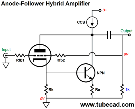
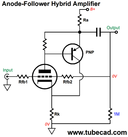
The circuit shown above uses an NPN transistor to vastly magnify the triode's transconductance. At the same time, the triode is in charge of the transistor. For example, if the transistor draws too much current, the plate voltage will drop, causing the cathode voltage drop in turn, resulting in the transistor being turned off. We can use a PNP transistor instead:
This version more closely reaches Super-Triode operation, as the triode works under nearly constant-current condition. The result transconductance is roughly equal to the inverse of the cathode resistor resistance. Using an N-channel MOSFET is more difficult due to the high base voltage needed to turn on the MOSFET, with the exception being lateral MOSFETs.
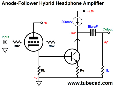
The big question is: Why would we need a hybrid anode follower circuit? One possible use would be in a headphone amplifier. Dynamic headphones require heavy current swing, but not big voltage swings—just the opposite of what tube do well, i.e. deliver big voltage swings, but weak current swings. The problem we face with all the previous hybrid anode-follower circuits is that the solid-state device sees the sam voltage drop as does the triode, which means a lot of heat. The workaround is to use two B+ voltage, one high-voltage B+ for the triode and one low-voltage B+ for the solid-state devices.
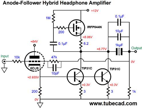
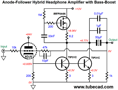
Note that only an AC feedback loop extends from input to output, as the output coupling capacitor blocks the DC voltage at the transistor's collector. Thus, the inclusion of the compliant-constant-current source (CCCS), denoted by the dashed circle. A CCCS will not establish a fixed current flow, but rather match the existing current flow, while fixing a set DC voltage at the collector. HEre is an example that uses an N-channel MOSFET.
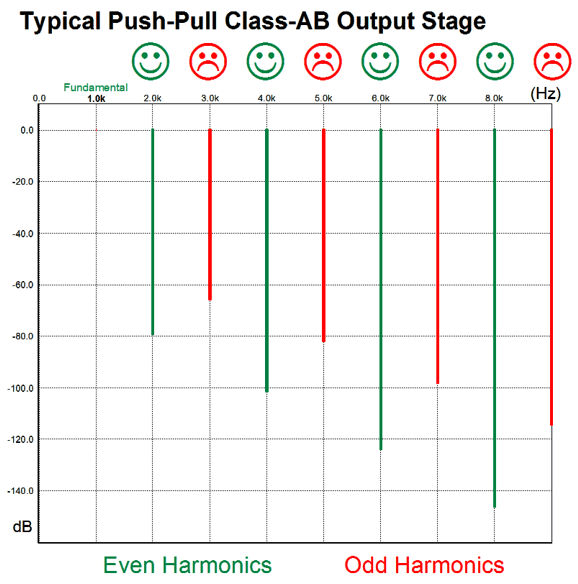
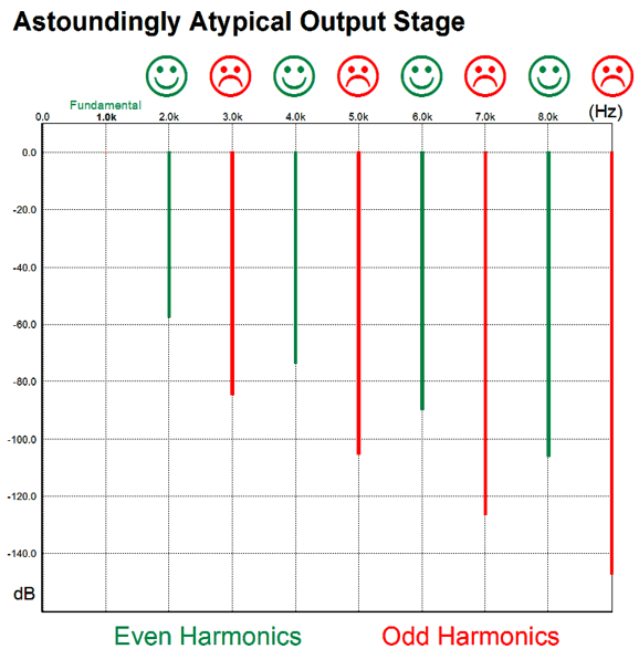
Note that the collector voltage is 6.77V, not 6V. Why? We could force the 6V collector voltage, but I choose the the slightly higher voltage as the two 3-ohm emitter resistors will see the 0.3V voltage drop double when the output voltage swings negatively into a low-impedance load. This hybrid headphone amplifier develops a gain of 3 (9.5dB) and can drive 32-ohm headphones (or lower impedance). With an idle current of 200mA, the output stage can swing clean +/-4Vpk. The 10pF capacitor is optional, but should be used with high-impedance headphones or when running unity gain. Okay, John, great another damn headphone amplifier. No, not quite, as this design delivers something amazing. First let's start with the typical push-pull amplifier harmonic signature, which both tube and sold-state amplifiers produce, as displayed below.
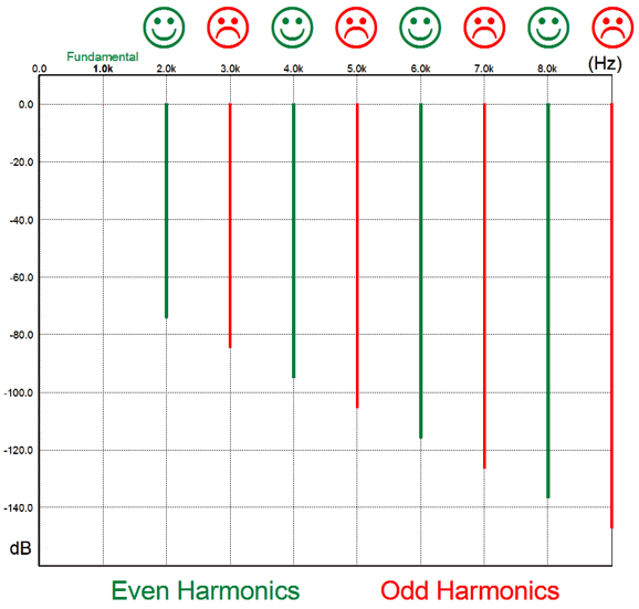
Odd harmonics are not as suppressed as much as are even-order harmonics. Odd harmonics, especially those beyond the third, irk the ear, with the 7th and 11th sounding particularly harsh. This is the sound you hear everyday. What you may never have heard is the following harmonic signature, as it is extremely rare.
This is what many believe that all single-ended amplifiers produce. They don't. Instead, we get an even downward progression.
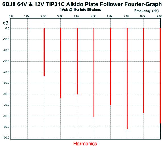
This is certainly far better than the push-pull structure, but it isn't as fine as the following.
This is the elusive sonic fingerprint. Since the CCCS holds an internal coupling capacitor and since the negative feedback loop encompasses the output coupling capacitor, we have to be careful to avoid excessive phase shifts, lest the negative feedback becomes positive feedback. On the other hand, we can create a bass boost by selecting the right capacitor values, as shown below.
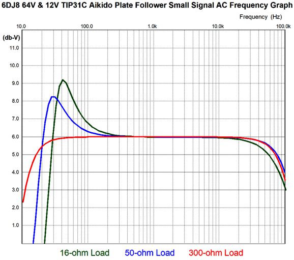
These smaller than expected capacitor values result in a bass boost with low impedance headphones, but no boost with high impedance drivers. In fact, since 50µF is relatively so small in value, we can use a film capacitor in place of the non-polarized electrolytic output coupling capacitor. Here is the frequency plots for three different headphone impedances.
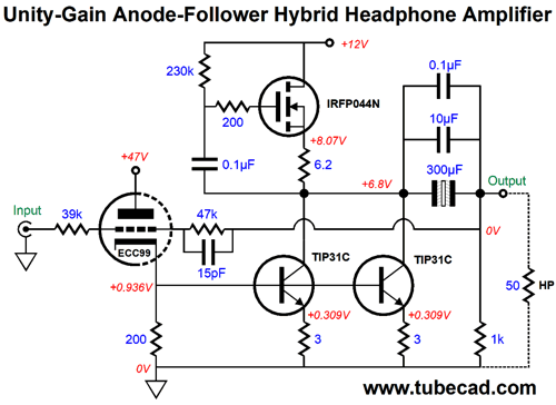
Okay, what I do not like about the above circuit is the awkward 63Vdc B+ voltage for the 6DJ8. In fact, I wish that 12DJ8 tubes were still made, as I would like to place the heater element across the 12Vdc power-supply rail. Here is an alternative version that uses an ECC99 instead, which holds a 12.6V heater.
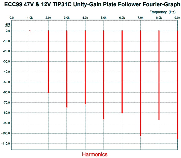
Note the unity-gain setup of the feedback resistors. The assumption he that this headphone amplifier would be used with a tube line-stage amplifier, so no extra gain would be needed. I had to evaluate this variation, as I was keen to see if the same astoundingly rare harmonic structure would still obtain. It does.
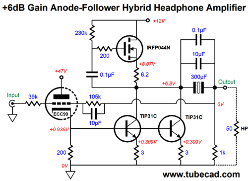
For those who would prefer some gain, so the headphone amplifier could be attached directly to a personal music player or DAC, the following version comes to the rescue.
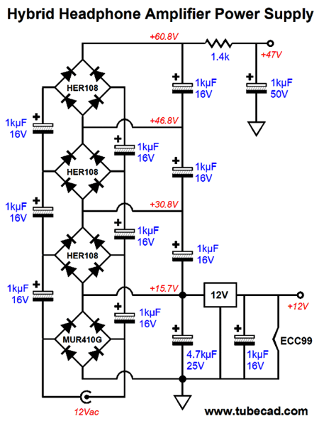
By the way, the 300µF coupling capacitor will work with load impedances down to 32 ohms; for 16-ohm loads, double its value. The 47Vdc B+ voltage allows us to get away with using a single 12Vac secondary or wall wart. Here is a full-wave rectified power supply.
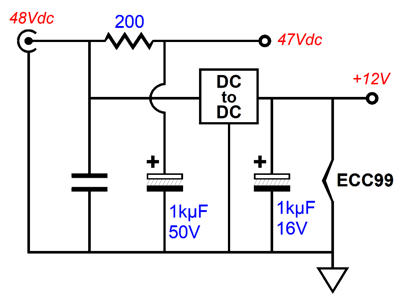
Actually, now that I look at it, I should have used 1kµF 25V capacitors instead of the 16V capacitors. Alternatively, we could a single 48Vdc switcher wallwart or desktop power supply and use a DC-to-DC converter to create the 12Vdc rail voltage.
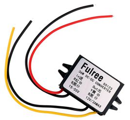
I recently ordered a 48V to 12V DC-to-DC converter from Amazon for only $7.13.
It has yet to arrive. When it gets here, I will let you know if it works out. (It might need a hash choke on its 12V output.) Notice how greatly this converter simplifies the power supply. And with a 3A rating, two channels drawing 200mA each and the heater drawing 400mA still leaves plenty of excess current delivery. One problem, however, with switcher power supplies and heaters is that cold heaters draw far more current than hot heaters. (See post 386 for more details and a workaround.) For example, a cold ECC99 heater presents only 4 ohms of resistance, which will draw 3A from the 12V converter, which might be enough to trip its current limiting circuitry. The workaround might be to use a staggered turn on, wherein the 12V heater sees a 10-ohm resistor in series, which gets shorted out once the tube is fairly warm. (A hot ECC99 heater presents a resistance of 31.5 ohms.) Okay, what if you have zero interest in any headphone amplifier, as you simply do not like headphones? Think bigger. If we can get this amazing harmonic structure from a small amplifier, why couldn't we get the same harmonic structure in a power amplifier? It's just a matter of scale, not topology. With a 24Vdc B+ voltage instead of the 12Vdc voltage, we could get at least 8Vpk voltage swings into an 8-ohm load, which equals 4W of power; with 48Vdc, 20Vpk and 25W. Mind you, we need an idle current of at least 2.5A for 25W of output into 8-ohm loads. Do not forget that the output stage runs in purely single-ended fashion. As the power output goes up, the more we should think about getting fancier still. For example, in order to establish a fixed idle current, we could apply a DC servo loop that adjusts the B+ delivered to the plate of the ECC99. In addition, we could feed the CCCS a DC reference voltage to set the optimal collector voltage. And, of course, many more TIP31C transistors and MOSFETs would be needed.
A third album with Moore is Bactrian, named after a type of two-humped camel. Moore is joined with David Friesen, another gifted and influential bassist and pianist. Yes, this album features dueling bass players.
It, too, is available at Tidal. Sadly typical of Tidal, Tidal offers an additional album with Friesen and Moore, Returning, but fails to list it under Glen Moore. It was recorded in 1993 and is excellent.
Before signing off, I have one last music recommendation to make, The Genuine Proprius Sound, which is an audiophile sampler album from the Proprius label, also available at Tidal. It holds a mix of musical styles and sounds amazing. (I once heard the SACD version and it was even better still.)
//JRB
User Guides for GlassWare Software
For those of you who still have old computers running Windows XP (32-bit) or any other Windows 32-bit OS, I have setup the download availability of my old old standards: Tube CAD, SE Amp CAD, and Audio Gadgets. The downloads are at the GlassWare-Yahoo store and the price is only $9.95 for each program. http://glass-ware.stores.yahoo.net/adsoffromgla.html So many have asked that I had to do it. WARNING: THESE THREE PROGRAMS WILL NOT RUN UNDER VISTA 64-Bit or WINDOWS 7 & 8 or any other 64-bit OS. I do plan on remaking all of these programs into 64-bit versions, but it will be a huge ordeal, as programming requires vast chunks of noise-free time, something very rare with children running about. Ideally, I would love to come out with versions that run on iPads and Android-OS tablets.
//JRB
|
|
John Gives
Special Thanks to the Special 76
I am truly stunned and appreciative of their support. In addition I want to thank the following patrons:
All of your support makes a big difference. I would love to arrive at the point where creating my posts was my top priority of the day, not something that I have to steal time from other obligations to do. The more support I get, the higher up these posts move up in deserving attention. Only those who have produced a technical white paper or written an article on electronics know just how much time and effort is required to produce one of my posts, as novel circuits must be created, SPICE simulations must be run, schematics must be drawn, and thousands of words must be written. If you have been reading my posts, you know that my lifetime goal is reaching post 1,000. I have 542 more to go. My second goal is to gather 1,000 patrons. I have 924 patrons to go. Help me get there.
Only $12.95 TCJ My-Stock DB
Version 2 Improvements *User definable Download for www.glass-ware.com |
||


| www.tubecad.com Copyright © 1999-2019 GlassWare All Rights Reserved |