| John Broskie's Guide to Tube Circuit Analysis & Design |
19 March 2019 Post 459
Interconnects
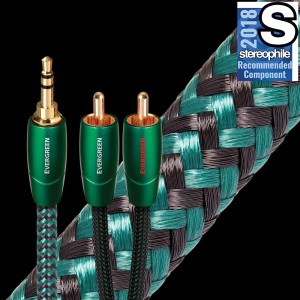
(In fact, one of my designs is being made—and sold for a mere $999.99—by a company whose owner emailed me asking for my help, which I gave freely, including my design; interestingly enough, I am not credited with its creation, as the company claims the credit. I never asked for any payment, so my not receiving any was expected, but my not receiving credit wasn't.) To be honest, I know that part of my cable indifference is born of anti-snobbery, i.e. my disdain cable-centric audiophiles; perhaps, I should have written "cable-eccentric" or "cable-egocentric." Surely you have met this fellow, the audiophile who frets and fusses over the expensive wire in his system. He is the audiophile who would prefer to listen to $200 loudspeakers with $20,000 speaker cables over $20,000 loudspeakers with $200 cables. He judges a system with his eyes, not his ears, as he need only look at the cables to grade the sonic merit. To be fair, I have met NOS-tube-centric audiophiles who won't listen to any recently-made tube. And I have known system-stand audiophiles who believe half an audio system budget should go to the equipment stands. And like all those who seek to buy perfection, all these hyper-centric audiophiles are never satisfied. Just as the brave die but one death and the coward dies a thousand deaths, the nervous audiophile never enjoys his system, while the steadfast music lover delights in thousands of hours playback. Having said all this, which I only stated to establish that I only turn to wire after all other electronic avenues are exhausted. (I remember a friend, having grown dissatisfied with his power amplifier, traveled to a high-end audio salon to seek remedy. He returned with $4,000 loudspeaker cables. Shockingly, amazingly enough, his amplifier didn't sound any better.) Okay, having said all that once again, I just bought a slightly fancy cable, an Audioquest Evergreen interconnect that holds a 3.5mm plug on one end and two RCA plugs at the other end. Why? I had been listening to my latest solid-state headphone amplifier, the one I described in post 454, and I wondered if the ultra cheap interconnect I was using was holding it back.
To be frank, it wasn't the cheap, non-gold-plated terminations that troubled me, but its age, as I had bought the cable over 30 years ago at Radio Shack and had recently found it in my box filled with scope cables. I feared that the wire within it might have oxidized, for given enough time the PVC sheathing will allow air to transpire to copper within. (It's fun to take apart old cable, both interconnect and power, and look at the state of the wire inside. It's enough to make even me nervous, having seen salmon-pink copper turn green, gray, and black.)
I bought the Audioquest Evergreen interconnect because it looked like my other Audioquest interconnects, the Columbia series that seems to have been replaced by the Yosemite series that is also battery polarized. The Audioquest Evergreen interconnect, however, isn't polarized and doesn't cost a fortune (less than $40, in fact). Once the new interconnect arrived, I turned on the solid-state headphone amplifier and let it warm up for half an hour. It actually does get warm, as it runs single-ended class-A output stages. I then picked the music track and left the cheap cable in place. Not bad sounding, not at all. I listened to the track twice. Now it was the Audioquest Evergreen interconnect's turn. Instantly, it sounded louder, say 1 to 2 dB louder. Nothing other than the cables had changed. Strange. It's impossible that the old wire's DC resistance was at fault, as I measured less than 0.2 ohms resistance and the headphone amplifier's volume potentiometer is 50k. No, the perceived volume difference was only subjective. In addition, I was surprised to hear something I had never noticed before in the music. Before, I had heard three strums of equal pitch and strength. Not this time. This time I heard three strums of equal pitch and increasing magnitude. Strum, strum, STRUM, not strum, strum, strum. Overall, the new cable was clearly a marked upgrade in sound. I plugged the old cables in and was surprised hear better sound than I had the first time. In fact, I now heard strum, strum, STRUM. What was going on? I have two theories. The first is that the Audioquest Evergreen terminations might have been coated in Stabilant 22, an electronics-contact enhancer. When I bought my Audioquest Columbia cables, they came with a small bottle of contact fluid, which I believe must be Stabilant 22. Here is an interesting aside. A decade ago, I held a tube rectifier shootout for a few audiophile friends. I had five or six rectifiers arrayed in ascending order of my preference. In the middle was an NOS Mullard GZ34 tube. Although still in the box, its pins were grossly corroded due to having sat for decades in a humid basement or garage. I dug out some fine steel-wool and went to work. The pins looked much better, but not perfect, so I applied a little of the Audioquest contact fluid to them. Well, this GZ34 sounded far better than I remembered it sounding. This troubled me and I replaced it with what I had deemed the worst of the rectifiers. It, too, sounded good. No doubt, some of the fluid had adhered to the tube socket pins. The result was that although each rectifier sounded slightly different, the big stratification had narrowed greatly. So, my first guess is that the RCA and 3.5mm jacks had retained some of the contact-enhancing fluid, making the old cable sound much better. My second guess is that my brain, having heard the new cable, now knew what sonic information resided in the music track and could now superimpose the newly acquired sonic knowledge to any repeated hearing of the track. We see actively and we hear actively, not passively. Our brain grinds away, making dimly perceived stimuli sharply focused. Only our nose's stimulation receives no extreme processing, unlike your dog's nose, which can smell in stereo, perceiving the direction of the scent. (I would love to smell with my dog's nose for one day, as his nose holds fifty times more scent receptors than my nose. Imagine what a supercharged wine snob I could become.) Because we never hear nakedly, neutral and objective stereo system evaluation is supremely difficult. For example, I know that my hearing differs through the day, being sharpest just before the sun rises and late at night. Perhaps this is so as that is the period when our ancestors were most at risk from a sneak attack. Or, possibly this is due to low electrical activity at these times; even the sun's huge electromagnetic output is shaded by the Earth then and most homes are on silent running. A good test would be to hold tests deep within a mine, where a thousand feet of dirt would shield both us and our equipment; or, perhaps, a Faraday shielded room would suffice to rule out the sun's effect upon our equipment and upon ourselves, but not wall voltage contamination, so a portable AC generator would be needed.
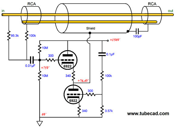
Simple Line-Stage Amplifier, But Not Too Simple
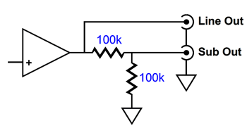
I presently use a two-resistor voltage divider that imposes a -6dB attenuation on the output signal that goes to my subwoofer amplifiers.
I do this for two reasons: the subwoofer amplifiers offer too much gain and I fear unwanted interaction between the solid-state sub amplifiers and the single-ended amplifiers for the main loudspeakers. For example, I have read of tape recorders messing up the sound when turned off, but still in parallel with the power amplifier inputs, as the solid-state circuitry only presented a high and linear input impedance when energized. So, long ago, I planned on trying a CCDA line-stage amplifier that held two outputs, one of them -6dB attenuated.
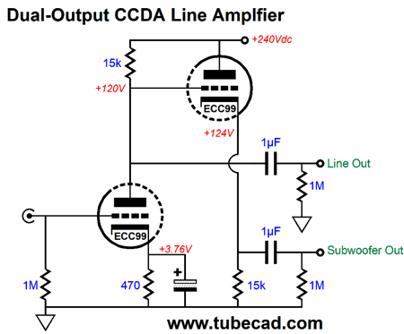
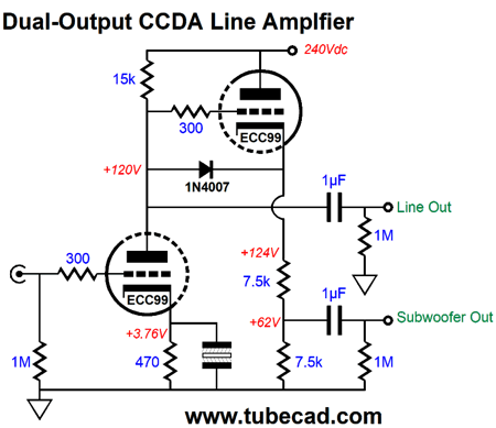
Note how the subwoofer output gets only 50% of the signal that the main output delivers. Also note that the two 7.5k cathode resistors in series combine to equal the 15k plate resistor. Remember that grounded-cathode amplifier's plate resistor and the cathode follower's cathode resistor must match in value to ensure constant-current draw. The 1N4007 diode is only there to protect the cathode follower triode at turn-on, so that is grid does not become 240 volts more positive than its cathode; with the diode in place, the maximum positive voltage differential is about 0.7 volts; once the triodes are hot, the diode falls out of the circuit, as it is no longer forward biased. Okay, let's flesh out this design.
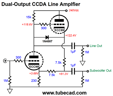
This is how I would build it. The cathode resistor bypass capacitor has been eliminated; a small amount of positive feedback has been injected into its operation. The idle current is 8mA per triode, for a total of 16mA per channel and 32mA for the entire line-stage amplifier.
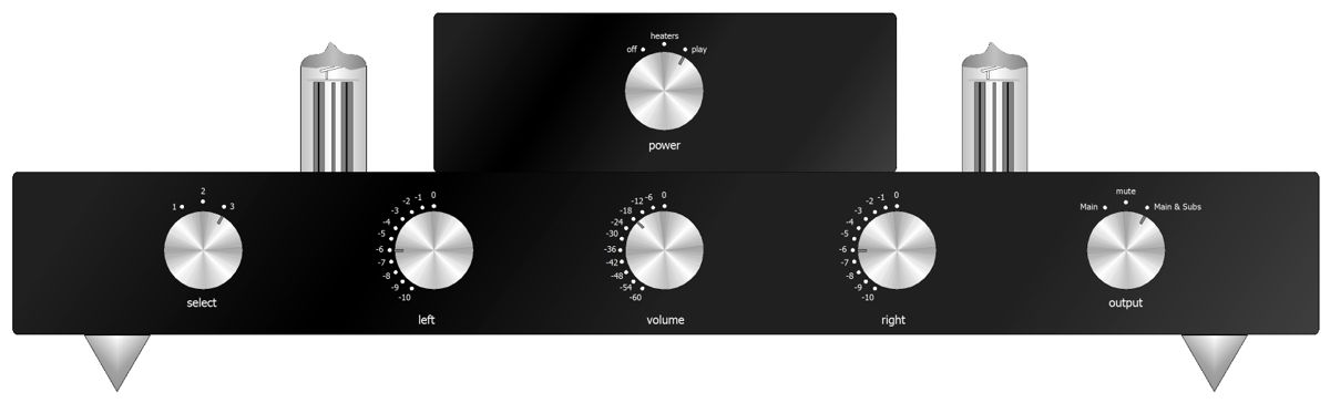
This is what I have in mind. The smaller enclosure (6in wide, 2in tall, and 10in deep) holds the two toroidal power transformers, AC power jack, and rotary switch, while the longer bottom box (17in wide, 2in tall, and 10in deep) holds the audio circuitry and PS-21 PCB. An interesting experiment might be to ground the top box to the house ground and ground the bottom box the signal ground, which assumes that plastic washers and bolts and nuts would hold the two boxes together and electrically apart. The rightmost knob offers three output choices: just the output to the main power amplifiers, mute, and both outputs to the main and subwoofer amplifiers. I bet that I could use two of my Noval Universal tube socket and PCB kits to let me create a semi point-to-point wired project.
The only big problem I can envision is the coupling capacitors, as they are big and heavy. Another approach to assembly is to use an internal sub chassis metal plate, which we could punch holes in to accept chassis-mount tube sockets. This solid metal plate could then be suspended by springs, much like some turntables that hang on springs rather than sit atop them. If the metal plate were made of solid copper, it could double as a ground plane. On the other hand, laying out a new PCB and having two made might ultimately prove the cheapest and fastest way to go.
Anode Follower Circuits More Anode Followers
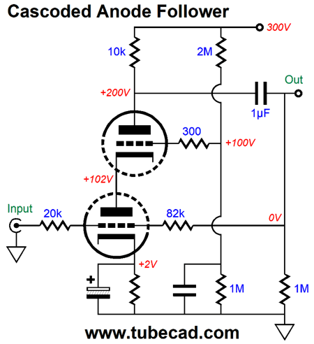
The top triode shields the bottom triode from Miller-effect capacitance increase, so we can expect much wider bandwidth, which means that we can use much larger-valued feedback resistor resistances. We can replace the top triode with either an N-channel MOSFET or NPN transistor. On the other hand, we can create a retrograde cascode by using either a P-channel MOSFET or PNP transistor. Why? We get all the benefits of a traditional cascode, such as elimination of Miller-effect capacitance and preservation of transconductance, with the added ability to send the input triode's amplification down to a negative power-supply rail, as shown in the schematic below.
This circuit appeared post 204. My goal was to create a functional equivalent of a solid-state OpAmp. Okay, what if we do not use a negative power-supply rail, terminating the collector resistor into ground instead?
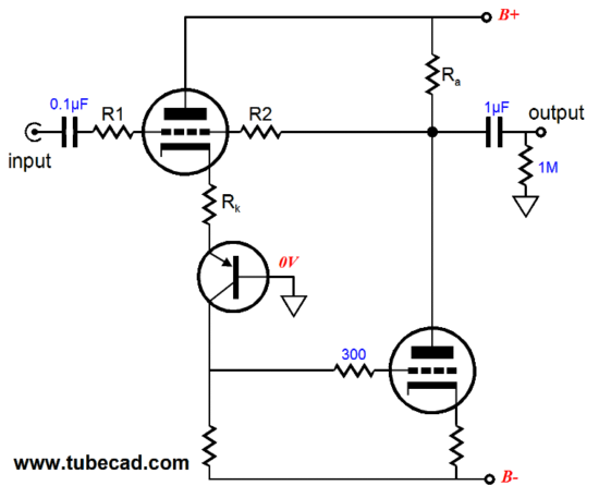
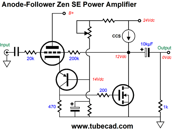
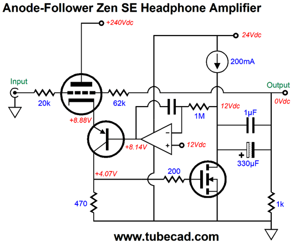
The triode indirectly drive the MOSFET's gate through the PNP transistor. The anode follower negative feedback loop monitors the MOSFET's drain voltage which it compares to the triode's cathode voltage. The potentiometer allows adjustment of the transistor's base voltage and, thus, indirectly allows us to center the output stage at 12Vdc at idle. Of course, we could replace the 470-ohm collector resistor with a constant-current source, but I wanted to keep the schematic simple. Let's look an actual design example: a Zen-like single-ended headphone amplifier.
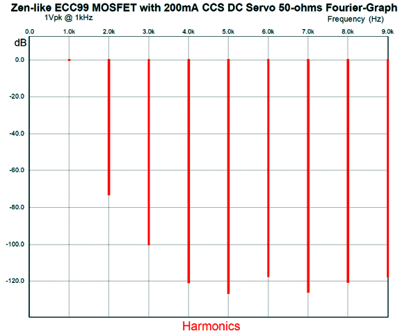
Note that the negative feedback loop extends to the other side of the output coupling capacitor(s). in other words, the triode no longer centers the output stage, which is why the OpAmp-based DC servo was added. The triode is an ECC99 and the OpAmp can be any unity-gain-stable FET-input type. In SPICE simulations, the PNP transistor was a 2N4403 and the MOSFET was an IRFP240. With the 200mA constant-current source, the maximum voltage swing into 32-ohm headphones would be 6.4Vpk; into 50-ohms, 10Vpk. Here is the SPICE-generated Fourier graph for 1Vp into 50 ohms at 1kHz.
The THD comes in at 0.022%. The output impedance is less than 1 ohm. Amazing results.
Compound Circuits
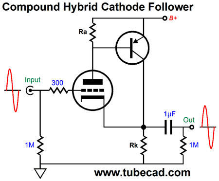
The compound configuration offers some real advantages, such as greater linearity and lower output impedance. But it is not perfect, as it works best in class-A output stages, not in class-AB stages. In fact, two compound circuits in opposition in a solid-state output stage only make gm doubling more severe. (I have a workaround, but let's stick to class-A output stages right now.) In addition, high-frequency stability can get squirrelly when the compound output stage is included in a global negative feedback loop. My own experience has been that whenever I have been disappointed by an emitter-follower's performance, the best remedy was to use a compound follower in its place. Nothing stops us from adding a P-channel MOSFET or PNP transistor to a triode and creating a hybrid compound circuit. For example, here is a cathode follower that uses a compound arrangement.
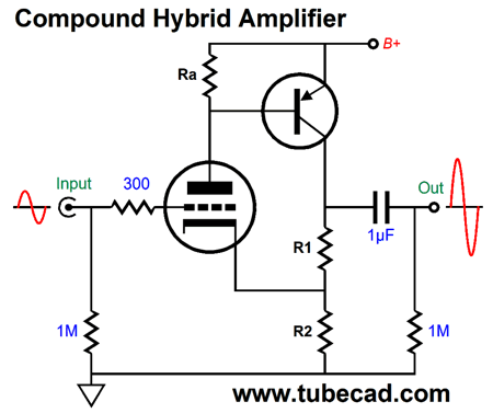
The triode operates in a Super-Triode mode, as its current flow is nearly constant and the PNP transistor is entirely under the triode's control. The result is a dramatically lower distortion and output impedance. What if we desire some gain? Easy enough, we just add one resistor.
The triode's cathode will still see a near unity-gain signal, while the top of R1 will see a gain roughly equal to (R1 + R2) / R2. For example, if R1 and R2 share the same value, a gain of 2 (+6dB) would obtain. Here is a fleshed out design example.
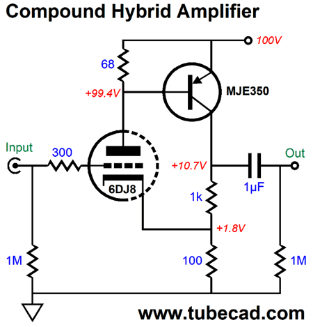
This hybrid signal amplifier delivers a gain of roughly 10 (+20dB) and runs off a relatively low B+ voltage of only 100Vdc. We can improve the circuit by adding an additional PNP transistor, as shown below.
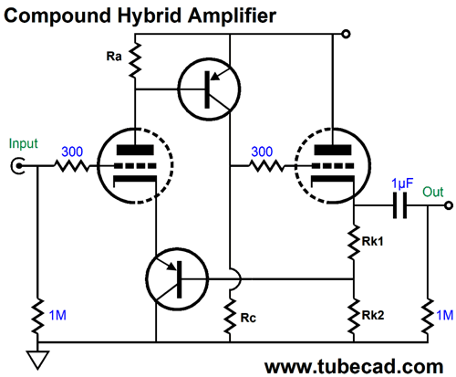
This added transistor need not be a high-voltage type, as the cathode voltage will only be a few volts above ground potential. This new arrangement greatly unloads the negative feedback resistors and allows us to run much less current through the top PNP transistor. Why would we want to do that? Less distortion. Moreover, we could use the second triode as a cathode follower and use its two cathode resistors as the negative feedback loop resistors.
This is not your father's compound amplifier. Note that there is no signal phase inversion. Also note that the cathode follower's output lies within the global negative feedback loop. If we do not need any gain, we can eliminate the top cathode resistor. In fact, we can use two B+ voltages, one for the triode and one for a low-voltage power transistor.
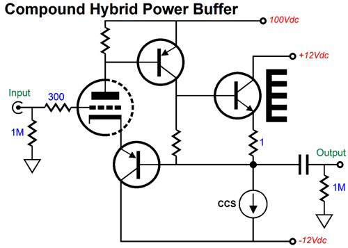
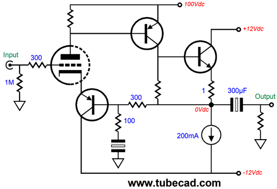
As long as we do not require big voltage swings from this hybrid buffer, this topology will deliver excellent performance. What if we do require bigger output voltage swings? Well, swinging up is not the problem, swinging down is. The workaround is to add a negative power-supply rail. Indeed, we can even get some usable gain out of the circuit.
The odd looking capacitor symbol denotes a non-polarized electrolytic capacitor. (The assumption behind its large 300µF value is that 32-ohm headphones will be driven.) We can go even further, as we can double up on the compound stages.
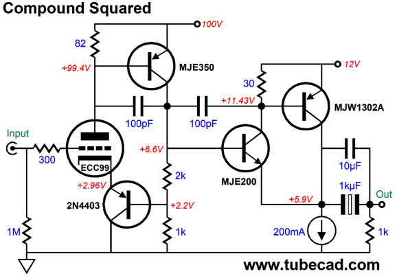
Compound Circuit Cascade
Note how the two compound circuits cascade without a coupling capacitor between stages. The ECC99 triode and its two PNP transistors define one compound circuit, while the NPN transistor and its enslaved PNP transistor complete the second compound circuit. In other words, two negative feedback loops exist in this circuit. If we wish, we can extend the input compound circuit's negative feedback loop to the amplifier's output.
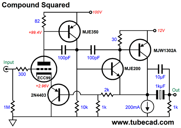
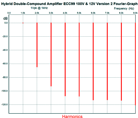
Note that the MJE350 PNP transistor's collector load resistance is now over three times greater, due to the 10k resistor, which will increase the input compound stage's open-loop gain. The 100pF capacitors ensure high-frequency stability. Here is the SPICE graph for 1Vpk into 50-ohms at 1kHz.
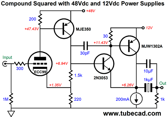
The THD is slightly less than 0.1%. I decided to try a vastly lower B+ voltage for the ECC99 triode, which meant losing one PNP transistor.
The THD was a bit higher, coming in at a little over 0.1%. Interestingly enough, I was able to get away with only one 30pF compensation capacitor. Okay, after this prolonged mental warm-up, let's move on to something unthinkable.
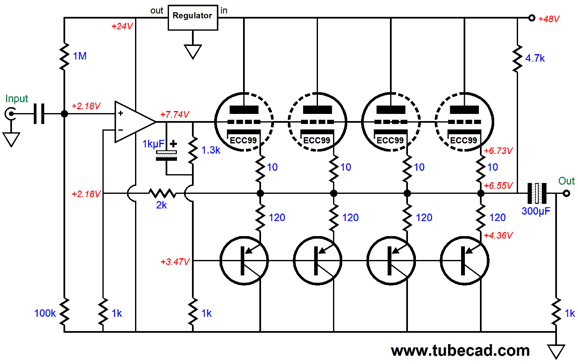
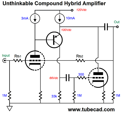
The Unthinkable Compound Circuit
The OpAmp is not gratuitously used in this circuit, as the ECC99 grids are being driven positively, which makes a low-impedance load, not a supremely high impedance. Had I used a 12AX7 grounded-cathode amplifier, there would be no way the 12AX7 could drive the grids positively. In addition, the four parallel PNP transistor bases also present a fairly low impedance, which the 1kµF capacitor tightly couples the OpAmp's output. Okay, let's now move on to a seemingly unthinkable compound buffer.
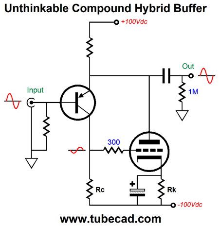
This is a unity-gain buffer whose triode is enslaved by the PNP transistor. To see how it works imagine that a positive pulse is forced upon the output, which will cause the transistor to dramatically increase its current conduction, thereby causing the triode to see a large positive pulse at its grid, causing its conduction to increase, which will help pull the positive pulse down. Conversely, if the externally applied pulse is negative, then both the transistor and triode will decrease in current conduction and the emitter/plate resistor will pull up against the negative pulse. Many might be wondering what good is this compound buffer when we can use the more traditional ordering of triode then transistor shown earlier here.
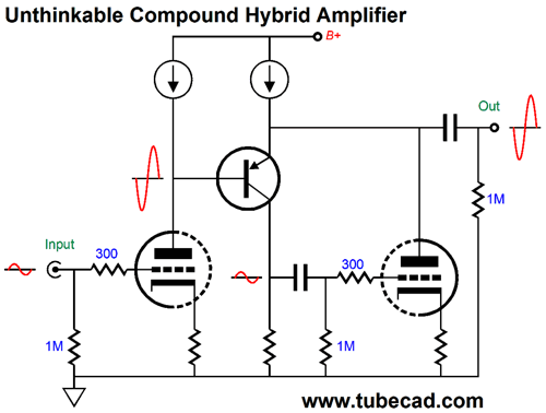
The good is found in thinking of all these circuit topologies as building blocks. For example, we take a grounded-cathode amplifier gain stage and cascade its output into the unthinkable compound and we get the following.
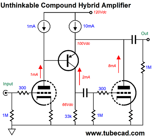
The unthinkable buffer acts much like a cathode follower, but with some important differences, such as it's being much closer to a true unity-gain buffer and its offering a vastly lower output impedance. An added bonus is that this complete amplifier circuit offers amazingly fine PSRR due to the two constant-current sources shielding the audio circuitry from the power-supply noise. Moreover, they allow us to run a surprisingly low B+ voltage.
Imagine a 12DW7/ECC832 dissimilar-triodes tube being used, with the 12AX7 triode being used in the input position and the 12AU7 triode used in the output position. Of course, we could use a twin-triode tube with matching triodes, such as the 6SN7 or 12BH7. We can even apply the anode-follower overly to the circuit, as shown below.
The two negative feedback resistors set the gain, as in any inverting OpAmp configuration.
Music Recommendation: Babe Singers Well, old prejudices die hard. For example, I immediately dismissed the possibility that Karen Souza, shown above, would be worth hearing. Way too attractive, I concluded. A mistake.
Remember the fun scene in the movie, High Fidelity, wherein Lisa Bonet sings Peter Frampton's song Baby, I Love Your Way and wows the John Cusack character? Well, that is how I felt after hearing Karen Souza sing songs that I thought I disliked intensely, such as Every Breath You Take and Bette Davis Eyes. Souza was born in Argentina and she is a fine jazz singer. What separates a jazz singer from a pop singer? Two things come to my mind: greater talent and more sincere emotional delivery. She has both . Start with her Velvet Vault album. The next babe singer that I have been listening to is Susan Wong, an Australian singer who was born in Hong Kong and is huge in Asia. I Discovered her in my search for more interesting covers of the famous song by The Mamas & the Papas, California Dreaming.
I have been a fan of Sophie Milman ever since I heard her cover the song that Elvis made famous, Fever. Then I forgot about her, until Tidal resurrected my interest in her singing. It turns out that she was born in Russia. I had no idea. Argentina, Hong Kong, and Russia—what an international array of female singers.
Okay, it's time to Diane Krall CDs behind us and give these female singers a listen. //JRB
User Guides for GlassWare Software Since I am still getting e-mail asking how to buy these GlassWare software programs:
For those of you who still have old computers running Windows XP (32-bit) or any other Windows 32-bit OS, I have setup the download availability of my old old standards: Tube CAD, SE Amp CAD, and Audio Gadgets. The downloads are at the GlassWare-Yahoo store and the price is only $9.95 for each program. http://glass-ware.stores.yahoo.net/adsoffromgla.html So many have asked that I had to do it. WARNING: THESE THREE PROGRAMS WILL NOT RUN UNDER VISTA 64-Bit or WINDOWS 7 & 8 or any other 64-bit OS. One day, I do plan on remaking all of these programs into 64-bit versions, but it will be a huge ordeal, as programming requires vast chunks of noise-free time, something very rare with children running about. Ideally, I would love to come out with versions that run on iPads and Android-OS tablets.
|
Special Thanks to the Special 79
I am truly stunned and appreciative of their support. In addition I want to thank
All of your support makes a big difference. I would love to arrive at the point where creating my posts was my top priority of the day, not something that I have to steal time from other obligations to do. The more support I get, the higher up these posts move up in deserving attention. Only those who have produced a technical white paper or written an article on electronics know just how much time and effort is required to produce one of my posts, as novel circuits must be created, SPICE simulations must be run, schematics must be drawn, and thousands of words must be written. If you have been reading my posts, you know that my lifetime goal is reaching post 1,000. I have 541 more to go. My second goal is to gather 1,000 patrons. I have 921 patrons to go.
The Tube CAD Journal's first companion program, TCJ Filter Design lets you design a filter or crossover (passive, OpAmp or tube) without having to check out thick textbooks from the library and without having to breakout the scientific calculator. This program's goal is to provide a quick and easy display not only of the frequency response, but also of the resistor and capacitor values for a passive and active filters and crossovers. TCJ Filter Design is easy to use, but not lightweight, holding over 60 different filter topologies and up to four filter alignments: While the program's main concern is active filters, solid-state and tube, it also does passive filters. In fact, it can be used to calculate passive crossovers for use with speakers by entering 8 ohms as the terminating resistance. Click on the image below to see the full screen capture.
Tube crossovers are a major part of this program; both buffered and un-buffered tube based filters along with mono-polar and bipolar power supply topologies are covered. Available on a CD-ROM and a downloadable version (4 Megabytes). |
||


| www.tubecad.com Copyright © 1999-2019 GlassWare All Rights Reserved |