| John Broskie's Guide to Tube Circuit Analysis & Design |
31 March 2019 Post Number 460
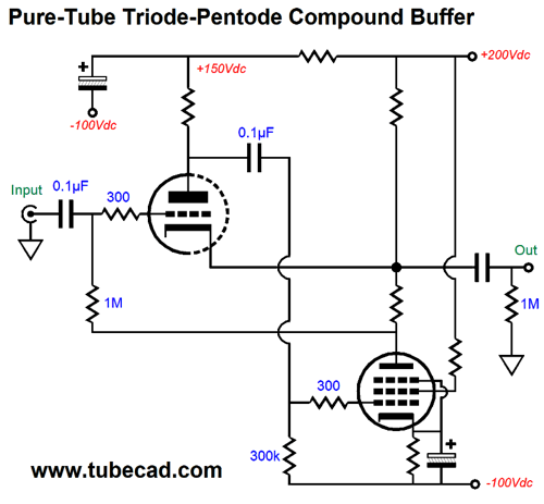
Pure Tube Compound Circuits
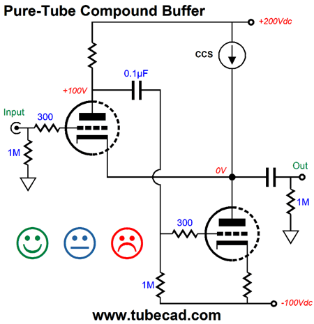
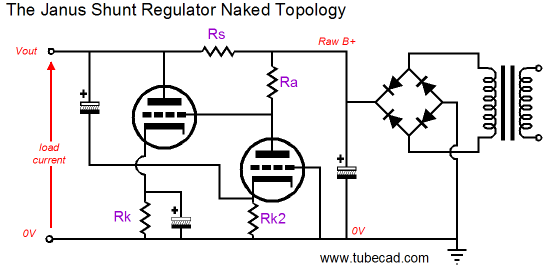
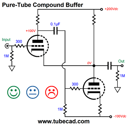
This is a buffer, not an amplifier. The output follows the input signal. The large-valued capacitor relays the AC output signal down below to the input triode's cathode. In other words, the input triode's cathode is monitoring the output signal, resulting in 100% negative feedback. For example, if an externally applied positive pulse is forced upon the output, that same pulse will appear at the input triode's cathode, causing the input triode's current conduction to plummet, which in turn will cause its plate voltage to skyrocket, delivering a huge positive pulse to the second triode's grid, prompting the second triode's current to also skyrocket, pulling the output back in line. Conversely, a negative pulse to the output causes the second triode's current fall, which will allow the constant-current source to pull up against the negative pulse. In a nutshell, negative feedback. This is half of the operating principle behind the Janus shunt regulator. (The other half being feed-forward ripple elimination.) In the Janus, the 12AX7 triode (on the right) compares the AC signal present on the DC output to ground, which holds no signal, and then prompts the 12AU7 triode (on the left) to counter any AC signal riding on the DC output voltage.
Now that we know how this circuit works, we can go about improving it. How do we start? I look for things I don't like and then seek workarounds. For example, I don't like the second triode's cathode resistor and bypass capacitor. The obvious workaround is to use negative grid bias instead, but that is too obvious for my liking, as I would prefer something more clever.
Note that we have a -12V power-supply rail, which can double has the heater power supply. We also need this power-supply rail so the buffer's output can swing +/-10Vpk without having the constant-current source become voltage starved. (In fact, a solid-state constant-current source IC may hold an internal shunting diode that would become forward biased in the event of voltage reversal across the IC's leads. Not good.) Well, it is easy enough to make a regulated -12V power-supply rail, which means that we would gain a free voltage -12V reference. The next question is: How can we put this free voltage reference to work for us?
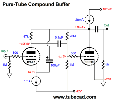
That's how. The 20Meg and 1M resistors in series define DC negative feedback loop with the secondary triode. If at idle, the second triode's plate voltage climbs too high, then its grid will see a portion of the rise at its grind and its current conduction will increase, pulling the plate voltage down. Conversely, if the plate falls too low, the gird will see a more negative grid voltage, causing the second triode to conduct less, and thus allow the constant-current source to pull up the plate voltage. Okay, what if we do not want to take a pure-tube compound buffer's output at the secondary triode's plate and what if we do not want to use a constant-current source, preferring to stay old school? The following compound variation achieves both goals.
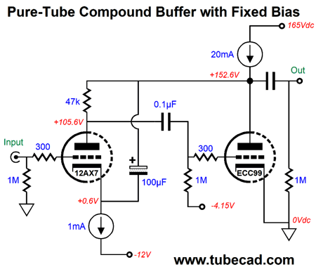
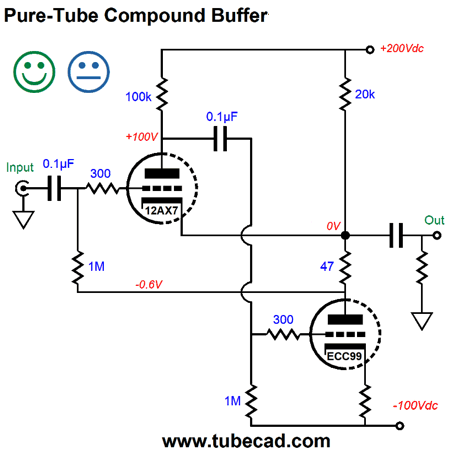
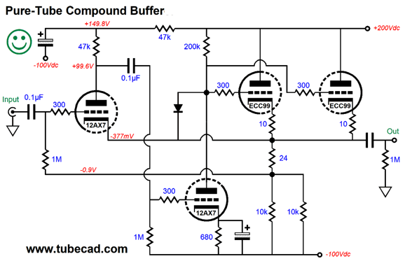
The 12AX7 cathode attaches directly to the output. Once again, the first stage uses all its gain to drive the secondary triode, forcing the second triode to work against any deviation of the output signal from the input signal. Why the three faces? This circuit might work supremely well in SPICE, but will probably fail to work in reality. How so? The input stage is DC coupled to the second triode's plate, but the input triode's plate is only AC coupled to the second triode's grid. In other words, the second triode's plate voltage must be at exactly the precise DC voltage to ensure that the first triode idles at the desired current. Just being 1 volt off will either completely turn of the input triode or saturate it. In fact, even if we got it to work in reality, it might stop working a year later as the tubes age or the wall-voltage drifts. What we need is a workaround that ensures that the buffer always works.
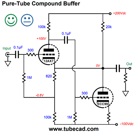
Note that 12AX7's grid is no longer DC referenced to ground; instead, it uses the ECC99's 47-ohm plate resistor as its cathode resistor. This resistor sees the combined current flow from both triodes. Another possible workaround is the following.
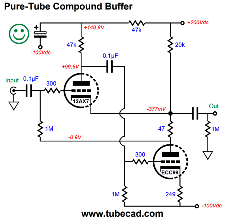
Note how the 12AX7's two cathode resistors get dragged along with the output. In both workarounds, the 12AX7's 1Meg grid resistor is effectively far, far greater in value, as its resistance gets bootstrapped by the buffer's output. In other words, the grid does not terminate into ground, but into an output that follows the input signal. This means that the input impedance is vastly higher, which in turn means that we could use a much smaller valued input coupling capacitor and still get decent low-frequency bandwidth. One problem that SPICE hides well—unless you purposely go hunting for it—is PSRR. Note that the input triode and its plate resistor effectively define a two-resistor voltage divider with the B+ ripple, which will be in anti-phase with the -100V power-supply rail ripple. The workaround is to add an RC filter to the input stage and terminate the RC capacitor to the negative power-supply rail, not ground.
Now the amount of ripple the ECC99 triode's grid sees relative to its cathode is greatly reduced. By the way, we could replace the second triode with a pentode and still stay true to the pure-tube goal.
The pentode sees a cathode-to-plate voltage of less than 100V, but its screen could see a much higher voltage, as the screen resistor attaches to the 200V B+ voltage. I had in mind a 6CW5/EL86 pentode, as this late-development pentode that can idle at a robust current flow in spite of low cathode-to-plate voltages. Note that this compound buffer is primarily a single-ended buffer. This means that it can pull down harder than it can pull up. Is that problem? I can be, depending on the load. For example, if the intended load is a single-ended output tube that will enter class-A2, then we would want just the opposite: the ability to pull up more than to pull down. Here is a possible workaround.
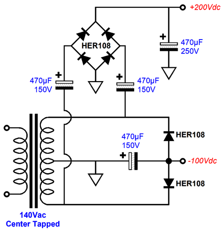
We end using both halves of both a 12AX7 and an ECC99. The ECC99 are configured as cathode followers. The diode is merely a safety device that prevents the ECC99 triodes from seeing a 300V voltage differential at start-up. The two 10k cathode resistor are in parallel so that we can use 2W resistors. (By the way, if you want to truly play it safe, you acknowledge that one of the ECC99 triodes may short from cathode to plate or you might, in an overly gleeful moment or after your third drink, plug the wrong noval tube into the ECC99 socket, and thereby short the 10k resistor to the B+ voltage, making a voltage diffence of 300V and producing 9W of heat in each 10k resistor. Not good, unless the resistor are rated for 10W each. Preparing for worst-case-scenario is seldom cheap or easy, alas.) No doubt some readers are worried about the power-supply voltages, as they are dissimilar, being +200Vdc and -100Vdc. Creating a suitable power supply is not difficult.
All that was needed was four capacitors and six rectifiers and one canter-tapped 140Vac transformer secondary. The bridge rectifier located above is driven by the two 470µF capacitors, which become polarized to 100Vdc. Another possible setup is as follows.
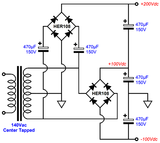
This version differs in that it requires five capacitors and eight rectifiers. It does offer the advantage, however, of having all the capacitors be the same value and voltage rating. Besides, the potential +100Vdc tap might come in handy elsewhere.
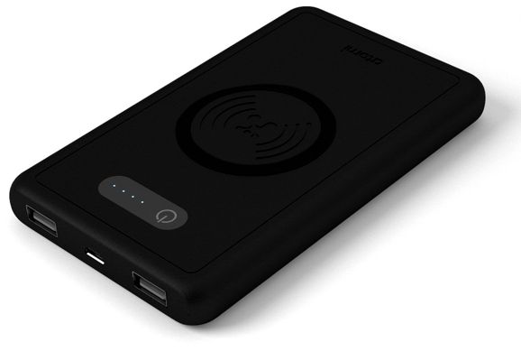
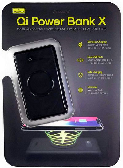
$30 DAC Upgrade Last week, I spotted several at Sam's Club and for less than $30 I bought an Atomi Qi USB charger, model AT1255. It can do wireless charging and is rated for 10,000 mA-hours. Dang, that's a lot. Of course, I instantly wondered what audio use to which it could be put. I remembered that my Project DAC was powered either by the USB signal source or by a 5Vdc wallwart with USB termination. Great news. I had tried a linear 5Vdc regulator before—and it worked fine with an optical connection, but not with my laptop. I don't know why. Well, the battery power supply works fine with both data terminations.
Compared to the switcher wallwart that came with the DAC, it sounds about 5 to 10% better, sounding more relaxed, more atmospheric. Is this a big deal? Yes, it is. Here is why: I now like a singer that I hadn't previously. Prior to the introduction of the battery-based power supply, I could not warm up to Cyrille Aimée. When I first heard her, I assumed she was purposely doing a retro cutie voice that was popular in the time of flapper hair styles. She wasn't. That was her real voice. With the battery-based power supply, her album, Let's Get Lost, not only became listenable, but enjoyable. (She really is an excellent singer.)
This is a big deal. As far as I am concerned, a huge deal. We can imagine many reasons for spending money on a good audio system, such as impressing our friends, interior decoration, helping your local audio salon make its rent, but these pale before the better reason: enjoyment of and appreciation of music.
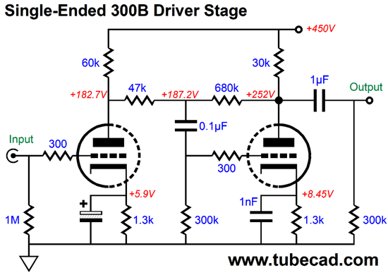
Aikido Single-Ended 300B Driver Stage
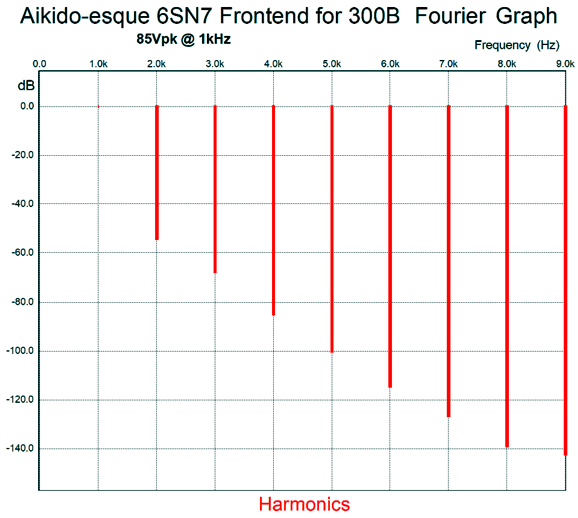
Did you note the inclusion of the negative sign? The ripple is not only attenuated, it is inverted in phase. Is that important? Normally, in PSRR measurements, it isn't; but in this application, it is of supreme importance. Here is why: the 300B exhibits an amplification factor of 3.8, which means that the plate is 1/3.8 times as effective in controlling current flow through the triode as the grid is. Well, by feeding the grid -0.26 of the ripple, with 0.26 being the reciprocal of 3.8, we achieve no change in current, which means that the 300B can no longer 'see" the power noise. And if the current doesn't respond to the B+ voltage ripple, the output transformer's primary cannot see any noise signal. The result is that at the secondary, where the speaker attaches, the PSRR is wonderfully low, as is the frontend's distortion, as the following SPICE-generated Fourier graph shows.
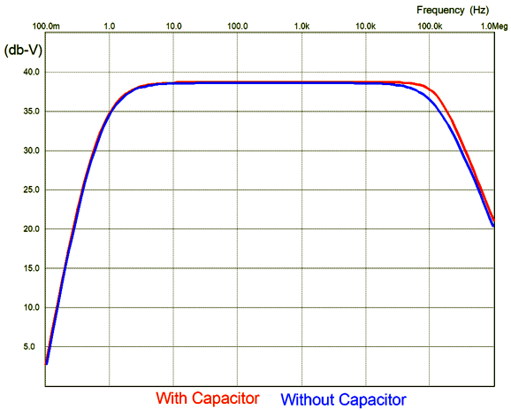
Note that this is at 1Vpk of input at 1kHz and 85Vpk of output. Nonetheless, the distortion is close to 0.1%. Just as importantly, the distortion goes in the right direction, with the downward swing exceeding the upward swing. Is that important? Yes. The 300B, like all other triodes, is easier to turn on than it is to turn off, so the negative swing should be slightly larger. If you are wondering what the 1nF capacitor is doing in the circuit, the answer is that boosts high-frequency response a tad.
Surprisingly enough, this is a simple technique (trick) that many tube-fanciers have failed to acquire. If the capacitor is too high in value, you will get a peaking high-frequency response. The best practice is to use a function generator and scope. By the way, a different output triode would require a different ratio of inverted power-supply noise to achieve an exemplary PSRR. One size does NOT fit all.
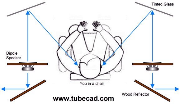
Something Completely Different: Near-Field Dipole Forty years ago or so, the now-demised USA audio magazine, High Fidelity, published a sister magazine devoted to classical music, which is where I first learned of near-field listening. I had to give it a try. Fortunately, I had the perfect speakers, four-foot tall, 8 inch square folded transmission-line enclosures with a Peerless 5-inch woofer and an Audex 1-inch dome tweeter in time alignment. The speaker suffered from a loss of bass due to diffraction loss at low frequencies. My workaround was to use a passive +4.5dB bass-lift network before the power amplifier. The result was a flat frequency response, but at a cost. The amplifier effectively became much less powerful and the speaker easily bottomed-out, as the 5-inch woofer had to do so much more work. Well, near-field listening eased the situation marvelously. With the speakers just three feet away from my ears, they played plenty loud. In many ways, the experience was a hybrid blend of regular loudspeaker and headphone listening—and, perhaps, the optimal listening arrangement. One problem we face is the spouse acceptance factor. Few will tolerate a listening chair and two speakers in the middle of the room. A second problem is that the speakers, being so close, no matter how small, obscure too much of our view. Now, we move onto the topic of dipole speakers. "Dipole" refers to two polar radiations, one in the front and one in the back, with deep sound nulls at the sides, the result of the front and back radiation being out of phase and meeting and canceling at the sides. If you have ever seen an electrostatic speaker or a Magnepan speaker up close, you have seen a dipole. Of course, we can use conventional speaker drivers mounted on a flat panel just as well. Here is my idea: we use two dipole speakers and reflector panels to beam the sound to our ears, which allows us to do near-field listening with the chair against a wall and our view unobstructed by two clear but tinted glass reflectors. Because the dipoles are situated in line with our ears, we cannot hear their output directly, only by reflection. The rear sounds hit the rear reflectors, making the rear radiation inaudible except by way of hitting the side walls and reflecting back much later.
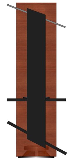
The big problem with dipole speakers is weak bass, due to the panel width being relatively small compared to low-frequency wavelengths. For example, a 40Hz wavelength is 28 feet long. Few would welcome a panel width of 14 feet. Here is the escape clause: since the speakers are near our ears, we can use mono subwoofer (or dual stereo subwoofers) located under the chair, with a relatively high crossover frequency, say 250Hz. Okay, John, this is all nice, but what holds the dipoles and reflectors in place? I have several ideas. Imagine we place a long but narrow woofer cabinet below the dipole and reflectors. As seen from above:
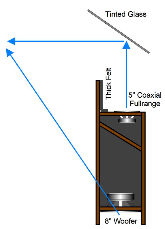
Then we could adhere a wooden bracing piece at the top to hold all three tall panels in place. On the other hand, if this design is a bit too avant-garde, then we could build something more conventional that uses a small coaxial fullrange and bigger woofer. Assume a relatively low crossover frequency of 250Hz.
This speaker would be placed in front of the listener in a near-field range. The critical goal would be to sit at the right distance so the two signals would arrive in time alignment. Okay, what if the glass reflector scares you, as you fear a burglar running into a sheet of glass in the dark and then your facing criminal charges for having booby-trapped your home. Well, how about something that could be used for near-field listening, but doesn't have to be used that way?
The idea here is that a short transmission-line enclosure would load the woofer. In many ways, this speaker would function somewhat as a dipole at low frequencies, as the out-of-phase rear wave leaving the woofer must travel down the line and exit and then travel through the distance to your ear. The closer you sit to the speaker, the deeper the bass response. What makes this design especially well suited to near-field listening is that the speaker would be visually largely invisible.
As we look at a speaker from our seated position, we see a seemingly small speaker that seems to be held up on a thin stand.
A nice optical illusion this. By the way, if you have experimented with near-field listening, you will have discovered that although the speakers are placed far lower than ear level, the soundscape can sound high. An acoustical illusion of sorts.
Music Recommendation: Mogwai's Every Country's Sun My guess is that if you love Pink Floyd, you'll like this album. If nothing else, this album gives your speakers and subwoofers a good workout. It was only after my second listening to the album that I got it. I can hardly wait to hear it a third time. The website, Pitchfork, offers an interesting review of this album. If you don't know Pitchfork, I recommend that you check it out.
//JRB
If you enjoyed reading this post from me, then you might consider becoming one of my patrons at Patreon.com
User Guides for GlassWare Software
For those of you who still have old computers running Windows XP (32-bit) or any other Windows 32-bit OS, I have setup the download availability of my old old standards: Tube CAD, SE Amp CAD, and Audio Gadgets. The downloads are at the GlassWare-Yahoo store and the price is only $9.95 for each program. http://glass-ware.stores.yahoo.net/adsoffromgla.html So many have asked that I had to do it. WARNING: THESE THREE PROGRAMS WILL NOT RUN UNDER VISTA 64-Bit or WINDOWS 7 & 8 or any other 64-bit OS. I do plan on remaking all of these programs into 64-bit versions, but it will be a huge ordeal, as programming requires vast chunks of noise-free time, something very rare with children running about. Ideally, I would love to come out with versions that run on iPads and Android-OS tablets. //JRB |
John Gives
Special Thanks to the Special 80!
I am truly stunned and appreciative of their support. In addition I want to thank the following patrons:
All of your support makes a big difference. I would love to arrive at the point where creating my posts was my top priority of the day, not something that I have to steal time from other obligations to do. The more support I get, the higher up these posts move up in deserving attention.
If you have been reading my posts, you know that my lifetime goal is reaching post number one thousand. I have 540 more to go. My second goal is to gather 1,000 patrons. I have 920 patrons to go. Help me get there.
Support the Tube CAD Journal & get an extremely powerful push-pull tube-amplifier simulator for TCJ Push-Pull Calculator
TCJ PPC Version 2 Improvements Rebuilt simulation engine *User definable
Download or CD ROM For more information, please visit our Web site : To purchase, please visit our Yahoo Store: |
|||


| www.tubecad.com Copyright © 1999-2019 GlassWare All Rights Reserved |