| John Broskie's Guide to Tube Circuit Analysis & Design |
25 May 2019 Post Number 466
PCBs Galore
Sliding or Steered Current Source? (By the way, the website, freepatentsonline.com, has a great list of wonderful patents, which is well worth examining.) Here is a quotation from the patent:
(Wow, I now understand how great is the urge to drop [sic] bombs.) Certainly, some push-pull amplifiers offer better efficiency than a single-ended amplifier; they are called class-AB or class-B or class-C amplifiers. Push-pull, class-A amplifiers, however, offer zero theoretical increase in efficiency over a single-ended amplifier that is inductively loaded, as both exhibit a theoretical maximum efficiency of 50%. In other words, we must compare class-A apples to class-A oranges. It's time for a quick recap.
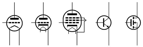
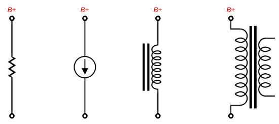
Single-ended amplifiers (and SE buffers) must run in class-A and require at least one active device, which could be a triode or pentode or MOSFET or transistor, and a high-impedance current path to complete a circuit with the power supply. This path can take the form of a resistor or an inductor or transformer or constant-current source—save for the constant-current source, all are passive. Constant-current sources, which are actually current regulators, can be made from a triode or pentode or MOSFET or transistor. In a constant-current source configuration, these active devices strive to emulate a passive device, such as a large-valued resistor or an inductor (a transformer's primary is an inductor), in that their goal is to present a high impedance current path to the power supply.
The least efficient load is the resistor (less than 9%), followed by the constant-current source (up to 25%), and the most efficient is the inductor or transformer primary (potentially 50%). Thus, with a theoretically maximum efficiency of 50%, getting 20W of output power requires dissipating at least 40W of heat at idle. Push-pull, class-A amplifiers and buffers do not improve upon this 50% limit. (We are only concerned with the output stage and we are ignoring such associated losses as input and driver stages, heater elements, fans, rectifier losses, transformer core eddy currents, and power lights.) If an amplifier puts out 20W of power but dissipates less than 40W of heat at idle, it cannot be a class-A amplifier, either a push-pull or a single-ended type; indeed, it must be a class-AB push-pull amplifier at full output. In other words, the amplifier might start out as a single-ended affair, but at its full output of 20W some form class-AB push-pull amplification must be taking place. In contrast, if an amplifier puts out only 10W of power but dissipates 40W of heat at idle, it might be a class-A push-pull amplifier or a single-ended amplifier—or an inefficient class-AB push-pull amplifier, for example, one that uses triodes as the output devices. Note that class-D and class-G amplifiers do not count; nor do my single-ended + class-C efforts.
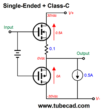
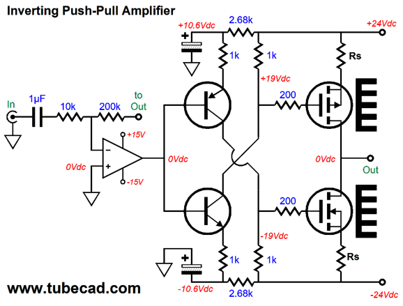
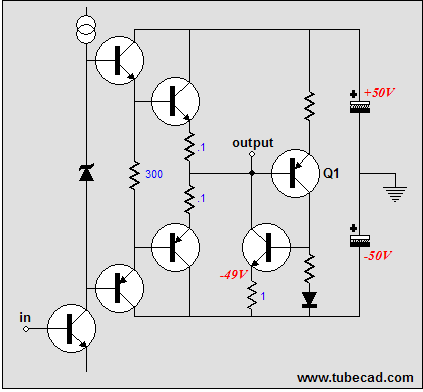
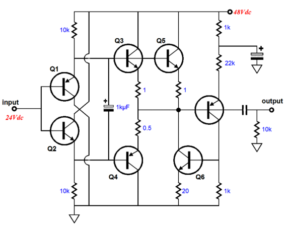
This output stage starts out purely single-ended and then, once the output exceeds a current threshold, the class-C P-channel MOSFET turns on and the output stage becomes a push-pull type.
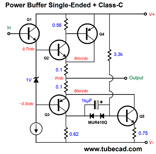
Once again, this output stage starts out single-ended, transistor Q3 is turned off at idle, and switches into push-pull, once Q3 conducts and the PNP transistor Q5 switches from being a constant-current source and actively responds to the input signal.
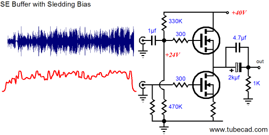
One day, we might get a single-ended power amplifier that work on what I have called sledding bias, wherein digital music files are played with a few seconds time lag, so both the idle current and B+ voltage can be varied to suit the upcoming demand. Think about it: there are no surprises in digital music files. In contrast, LP playback and FM tuner and live music feeds are fraught with uncertainty. The needle might encounter a deep scratch or break in half; the radio program could be interrupted for an alert message; and the musicianby breaking a string and audience could surprise us by coughing. A digital file on your hard-drive is like the novel on your bookshelf: nothing in the story is going change since it was printed. If a loud scratching sound is heard it is because it was recorded on the digital file; if novel ends sadly, it will always end sadly. Because the digital file can hold no surprises, we can design a high-power single-ended amplifier that is cool to the touch at idle and roars with crescendos. All we have to do is find out ahead of time what will be demanded by the digital file and give the single-ended output stage what it needs in terms of current flow and B+ voltage to reproduce the upcoming musical event. On the other hand, if the DAC or CD player put out two signals per channel, one of the music and one of the current-voltage envelope shape, then no time lag would be needed.
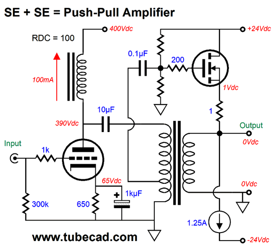
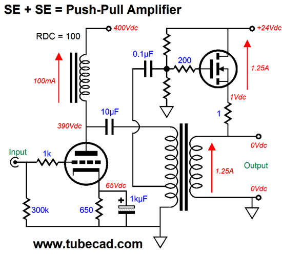
Take the circuit shown above and apply the red trace to the B+ voltage—or rather to a switching power supply that would deliver the needed B+ voltage as the music demands. Returning to the world of conventional output stage topologies, a single-ended output stage can only deliver a maximum current swing into the speaker equal to its idle current; a class-A push-pull output stage can only deliver twice its idle current, but at twice the B+ voltage in a totem-pole arrangement or twice the the combined current in conventional transformer-coupled design, so no net improvement in efficiency obtains. In other words, two 300B tubes in a parallel single-ended amplifier are just as efficient as two 300Bs in a class-A push-pull arrangement.
The output transformer's winding ratio multiplies the current by its ratio. For example, a 10:1 winding ratio implies an impedance ratio of 100, so an 8-ohm load is reflected to the primary as 800 ohms; the primary voltage swings are reduced by ten at the secondary, while the current swing at increased tenfold.
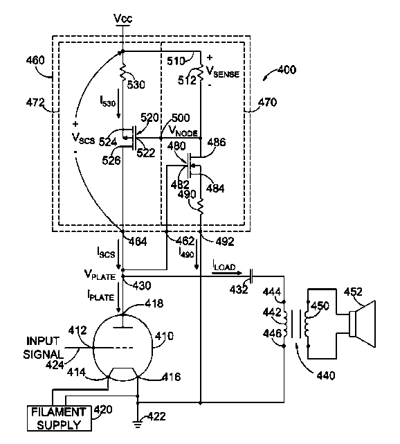
Okay, what can we say about the following, newly invented and patented output stage topology?
No doubt, the patent drawing for the paperclip was a confusing mess, as that is way of the patent. Here it is redrawn.
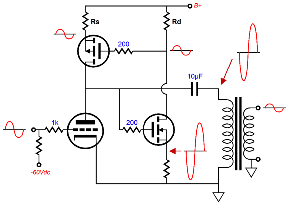
It certainly looks unconventional, but is its operation as unconventional as its appearance? First, let's add some signal relationships throughout the circuit.
The triode receives the input signal at its grid. As the signal swings positively, the triode increases its current conduction and its plate voltage is pulled down, which then pulls down N-channel MOSFET Q2's source voltage, which in turn provokes a decrease in the voltage drop across its drain resistor, making P-channel MOSFET Q1 draw less current. When the input signal swings negatively, the opposite occurs; the triode draws less current and MOSFET Q1 draws more current, pulling the triode's plate voltage up. The capacitor coupled output transformer relays this amplified signal to the loudspeaker. In short, push-pull operation, not single-ended functioning, as MOSFET Q1 actively varies its current flow match the triode in anti-phase, just like every other push-pull output stage.
The patent claims that this a para-feed arrangement, but really is just a push-pull totem-pole arrangement of dissimilar output devices with a coupling capacitor attaching to the output transformer's primary, which allows us to use a non-air-gapped output transformer. In fact, we could just as easily use a bipolar power supply and DC coupled the output transformer primary at one end and ground the other end. The patent goes to great lengths to state that the P-channel MOSFET Q1 varies is current conduction in anti-phase to the triode: the very definition of push-pull operation. The patent also stresses that the output stage is single-ended, an attribute highly esteemed.
Okay, let's pause look at MOSFET Q2 and what its purpose is in the circuit. It is an after-the-fact phase splitter, which could have otherwise been setup to be a before-the-fact phase splitter. Indeed, we could lose it altogether, driving (steering) the P-channel MOSFET with the same signal that drives (steers) the triode. .
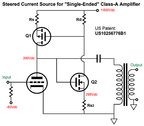
Here we see the P-channel MOSFET being driven by the same input signal as the triode. As the input signal swing positive, the triode conducts more; the MOSFET, less. As it swings negative, the triode conducts less; the MOSFET, more. In short, push-pull anti-phase current swings. Note the resistor Rs is a 550-ohm source resistor. Why so high a value? We need to match the triode's effective transconductance to ensure optimal and equal current swings. Also note the way the P-channel MOSFET is biased. The two unmarked resistors define a two-resistor voltage divider that imposes a DC negative feedback loop for the MOSFET. If the MOSFET sees too large a voltage drop, the MOSFET current conduction increases, which applies the brakes to any further voltage drop. So is this a perfect push-pull output stage? No. The MOSFET's drain offers a nearly infinite output impedance, while the triode offers a relatively low output impedance. If we replace the triode with an N-channel MOSFET, we get this amplifier, which exhibits so high an output impedance that the amplifier constitutes a current-out design.
How do we get a low output impedance? Here is on way.
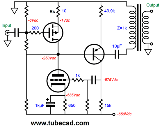
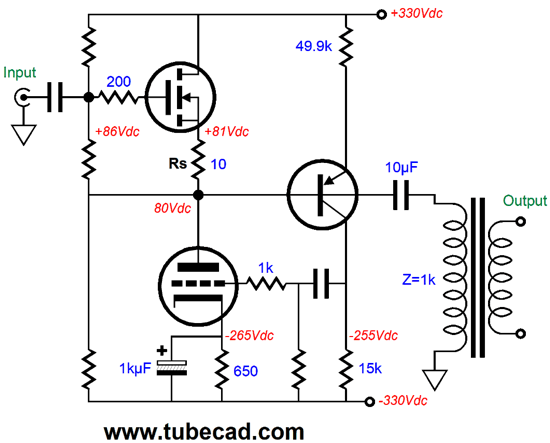
The OpAmp provides the needed negative feedback to both keep the output centered at 0V and to lower the gain and distortion. Why not just flip the MOSFETs, so N-channel sits atop the P-channel, creating a push-pull source follower configuration? The problem with non-lateral MOSFETs is that they present so high a turn-on voltage that the full potential power is seldom realized, as the driver stage cannot swing the required voltage beyond the power-supply rail voltages. This awkward-looking arrangement sidesteps that problem, without resorting to bootstrap capacitors or higher power-supply rail voltages for the input and driver stage. Okay, let's return to the freshly patented output stage, but with a a slight twist.
I switched to cathode-bias and upped the idle current. In addition, I had to add the grid and gate stopper resistors. The added coupling capacitor and the two-resistor voltage divider help stabilize the output stage at turn-on and help center the output stage.
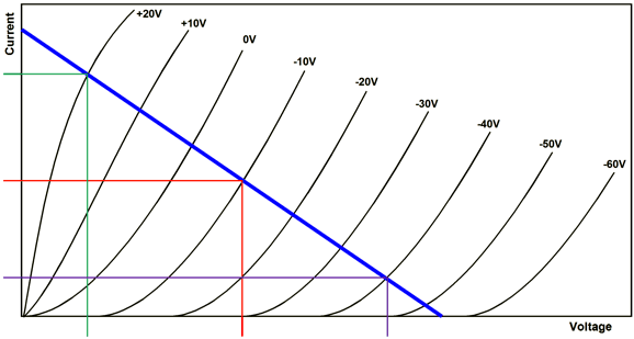
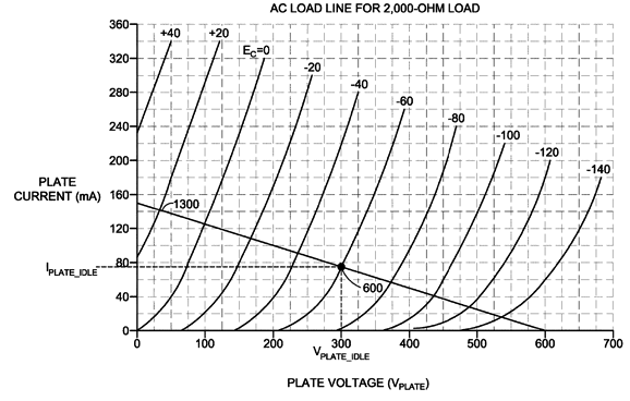
Implicit in the patent (and possibly explicitly stated, but my eyes began to glaze over while reading the patent) is the assumption that class-A2 would be used, something I would want to avoid. Here is the 300B plate curves and load-line found in the patent.
The question that needs answering is, how big are the voltage swings needed to develop 20W across a 2k load? We find the answer with the following formula: Vpk = √(2WRload) So what is the peak voltage swing? 283Vpk Note where the load-line intersects 17V and 283V. To get to 17V, the grid voltage will have to be over +20V. By the way, I don't believe the graph—well, at least not all of it. First of all, the load line shown is for 4,000 ohms, not 2,000 ohms. How do I know that? Divide 600V by 150mA or 300V by 75mA and you get 4k, not 2k. Second, does anyone really believe that a 300B will draw 150mA with a cathode-to-plate voltage of 0V? I don't. My LiveCurves math model predicts what curve traces show, bending of grid lines at plate voltages below 10V.
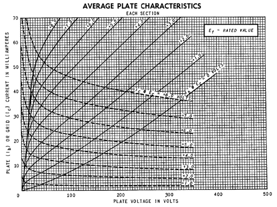
Here is the plate curve for a 12AT7, which shows the typical bending at low plate voltages.
Why does the patent claim to have created a single-ended amplifier topology? My guess is that, other than confusion, the assumption was if there is only one output tube, then the amplifier must be single-ended. Most audiophiles would certainly agree. The fact that you are a regular reader of the Tube CAD Journal, however, sets you apart. You know that active devices take many forms, such as triodes, pentodes, MOSFETs, and transistors. You know that "steered" and driven and impelled and goaded and guided and directed and controlled all mean the same thing. In a conventional push-pull tube-based amplifier, the phase splitter "steers" the output tubes in anti-phase current swings. You know that just because a MOSFET doesn't look like a 300B doesn't mean it cannot be used with a 300B in push-pull output stage. You know that dissimilar technologies can function in a similar way. The US Patent office isn't as lucky. Albert, we need you.
Imagine if some enterprising fellow created a car that used a battery-powered electric motor to drive the rear wheels, while a gas engine powered the front wheels. The press release would claim twice the mileage per gallon than had been previously been achieved. But what about the battery? Do not worry about it, as it only "steers" the electric motor's rotation. Perhaps, if the output MOSFET had been an N-channel type, rather than a P-channel, the push-pull functioning would appear more obvious. For example, here is a push-pull output stage that uses a triode and an N-channel MOSFET. It, too, is something of a lazy affair, as the triode must create the needed anti-phase signal for its solid-state push-pull partner.
The MOSFET is driven (steered) by the output transformer's extra tap, which delivers a slightly larger voltage swing than what the triode's plate sees. This larger signal then drives the MOSFET in anti-current-phase relative to the triode. For example, a positive input signal provokes greater current conduction from the triode, which forces its plate voltage to swing negatively, which delivers a negative signal swing to the MOSFET's gate and the MOSFET decreases it conduction.
If this still seems confusing, just replace the MOSFET with a triode.
The top triode will require a much bigger input signal than the MOSFET did, but the same push-pull operation obtains. By the way, this circuit reveals the mistake of calling this arrangement a para-feed, as the top triode does not shield the primary from the power-supply noise, while an inductor would. Okay, let's now stand things on their head, with the triode atop the N-channel MOSFET.
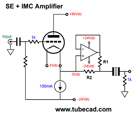
This is a unity-gain push-pull output stage. The triode's cathode follows its grid. If the output swings positively, the MOSFET sees its gate voltage drop, so the MOSFET lessens its current conduction. Conversely, if the output swing negatively, the triode conducts less, while the MOSFET conducts more. In a nutshell, push-pull operation. By the way, as I look at this last schematic, I immediately think: How could I impose an Aikido-mojo overlay. The solution would be to inject a portion of the power-supply noise to the base of the NPN transistor, which would force a noise null at the output. Another example that uses an N-channel MOSFET would be the SRPP.
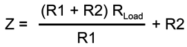
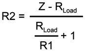
When the triode conducts more current, the MOSFET sees is gate voltage fall, causing the MOSFET to conduct less current. When the triode conducts less, the MOSFET conducts more, as it sees its gate-to-source voltage rise. (The best way to understand this topology is to think impedance-multiplier circuit (IMC), rather than hybrid SRPP, as the MOSFET source output impedance is so low that that the IMC formula for impedance multiplication works well. Impedance' = Z(R1 + R2)/R1 In this example, the triode effectively sees a load impedance twice the actual impedance. While on the topic of impedance-multiplier circuits, we can add the IMC after the fact, as in on the secondary side of the output transformer in a true para-feed amplifier.
The 8-ohm load appears as a 17-ohm to the secondary, which doubles the load seen by the triode. Now, the question is: Is this amplifier a single-ended affair? The answer depends on what type of amplifier is used inside the IMC. If it is a single-ended type, then could call it a single-ended cascade amplifier. Much more likely, however, the IMC's internal amplifier will be a solid-state push-pull type. Another possible arrangement would be to forgo the output transformer altogether and let the IMC magnify the load impedance sufficiently to make the 300B triode happy. The formula that reveals the impedance (Z) that the 300B will see is If we solve for R, we get: Thus, if we want an 8-ohm speaker to appear as 200-ohm load to the 300B and R1 equals 1 ohm, R2 must equal 21.33 ohms. (Two 43-ohm resistors in parallel gets us close enough.)
This circuit is a buffer, not an amplifier, although it could be the output stage of a more complex amplifier. I get many requests for a 300B-based headphone amplifiers. Well, this circuit would allow the 300B to indirectly drive 16-ohm headphones, with reduced rail voltages. Returning to the totem-pole IMC—I mean the SRPP—we use a P-channel MOSFET instead of an N-channel type in the cathode-follower arrangement.
This SRPP (IMC) operates in a push-pull fashion, just like the N-channel version, but works as cathode follower and not a grounded-cathode amplifier. In short, using a P-channel MOSFET does not sidestep the push-pull label. This buffer could drive headphones, but not speakers. John, John, don't you get it? The patented circuit uses a single triode, so it must be single-ended. Other than the patent holders, I cannot imagine anyone actually saying such a thing. Here is another approach we can take to show that the P-channel MOSFET is really a driven output device, not a steered-current regulator.
When I stand circuits on their head I do it with gusto. Both the P-channel MOSFET and the triode work in a push-pull fashion. Since the MOSFET receives the input signal, should we call this a MOSFET-based single-ended amplifier with a steered triode? It might make the advertising department happy, but it make little sense, when push-pull operation is clearly on display. Note the absence of a B+ voltage. Instead, we find a negative power-supply rail voltage. Instead of the triode receiving the input signal, the P-channel MOSFET does. Instead of the MOSFET being "steered," the triode is steered. By the way, we can use an N-channel MOSFET instead and a bipolar power supply.
This is a unity-gain output stage. The triode functions in the same way in both cases, as an appositional or oppositional partner in a push-pull output stage. John, don't you get it? The steered constant-current source is a brilliant innovation that allows us to double a single-ended amplifier output, while still claiming single-ended bragging rights. Actually, I do get it, which is why I have shown what I have called "the sliding constant-current source" at least twice before. The first time was in post 88 back in 2006.
The second time was in post 187 in 2010.
The devices differ, bipolar transistors rather than MOSFETs, but the topology remains the same as appears in the patent. The functioning also remains the same: the greater the voltage differential across the circuit, the less the current conduction; the less the voltage drop, the more the current flow. The goal was to create an NR (Negative Resistance). Okay, here is one last circuit that shows two seemingly single-ended devices being combined to create a push-pull output stage.
As the triode conducts more, the MOSFET conducts less; as the triode's current flow abates, the MOSFET's flow augments. The output transformer provides the MOSFET's input signal. Current phasing is all important here. If the triode and MOSFET work in current-phase, they would effectively be working in parallel and the amplifier would be entirely single-ended; But if they work in anti-current-phase, the amplifier becomes a push-pull type. By the way, if we use an air-gapped output transformer, we could lose the MOSFET's constant-current source.
Note how the transformer's primary functions as an AC voltage divider. (We could derive the MOSFET input signal from the triode's input signal, after its passes through a two-resistor voltage divider, but excessive phase shifts might impair performance.)
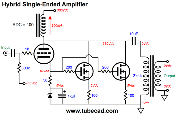
To sum up, what bothers me about this patent is that muddies up the distinction between a single-ended and push-pull. The claim that an SCS, a steered current source, is both operating in a push-pull fashion and is single-ended at the same time is crazy. I hate distinctions without a difference. Having said that, perhaps the amplifier will actually sound more single-ended than push-pull, as the lazy, after-the-fact phase splitting might double the triode's distortion, whereas placing the phase splitter before the triode might reduce the output distortion. Moreover, the SCS presents a high impedance, which was its goal, so the only source for a low output impedance is the triode. In other words, expect a very poor damping factor, which might sound great with some loudspeakers, but worse with others. Nonetheless, a better approach would be one of my super-triode efforts, as they result in lower distortion and output impedance. One possibility be this hybrid para-feed amplifier.
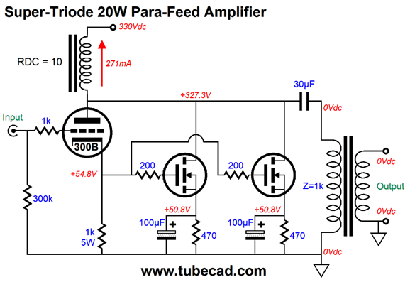
Why two MOSFETs? Heat. Each N-channel MOSFET draws 50mA, while the triode draws 100mA, which means that the triode will dissipate 35W and the each MOSFET will dissipate 17.75W. (We could place a drain resistor, say 1400 ohms, atop each MOSFET to unload some heat, as we are only striving for voltage swings of 200Vpk.) By the way, in the patent we learn that three P-channel MOSFET are used in triple cascode to extend their limited voltage ratings (and divide the heat each dissipates by three). In this hybrid single-ended amplifier, the MOSFET are enslaved by triode and they like power current mirrors. This is a true para-feed, as the inductor shields the triode and MOSFETs from the power-supply noise. Here is a Super-Triode version.
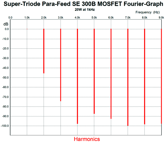
The 300B triode undergoes less than 1mA of current variation at full output. In SPICE simulations, with a 30H inductor, the THD was less than 1% at 20W; at 1W, the THD almost hit 0.1%.
Another possibility would be to go push-pull with an SRPP (IMC) output stage.
This version is far simpler and does not require a huge inductor; nonetheless, the PSRR is excellent, but the THD is higher at full output. In addition, the B+ voltage is scary high, whereas the previous version used a far lower 330Vdc, which could be developed by rectifying a 240Vac secondary. Moreover, this version requires a much larger input signal and a negative power-supply rail. If I were to build one of these designs, I would go for the Super-Triode version, but I would use four MOSFETs to spread the heat out.
Music Recommendation: Anne Bisson Here is a paradox: the closer an artist comes to perfection, the greater is our inclination to nitpick. Ms. Bisson belongs to the top 1% of singers, so the urge to find fault is great. I will resist this petty inclination. Fortunately, Tidal offers the following four albums from her.
But Tidal, being Tidal, hides a fifth album, conversations, which you find by searching for "Vincent Bélanger, Anne Bisson."
Be sure to listen to the entire album, as it holds an eclectic mix of genres. Wonderfully recorded, as well. //JRB
If you enjoyed reading this post from me, then you might consider becoming one of my patrons at Patreon.com
User Guides for GlassWare Software
For those of you who still have old computers running Windows XP (32-bit) or any other Windows 32-bit OS, I have setup the download availability of my old old standards: Tube CAD, SE Amp CAD, and Audio Gadgets. The downloads are at the GlassWare-Yahoo store and the price is only $9.95 for each program. http://glass-ware.stores.yahoo.net/adsoffromgla.html So many have asked that I had to do it. WARNING: THESE THREE PROGRAMS WILL NOT RUN UNDER VISTA 64-Bit or WINDOWS 7 & 8 or any other 64-bit OS. I do plan on remaking all of these programs into 64-bit versions, but it will be a huge ordeal, as programming requires vast chunks of noise-free time, something very rare with children running about. Ideally, I would love to come out with versions that run on iPads and Android-OS tablets. //JRB |
John Gives
Special Thanks to the Special 84!
I am truly stunned and appreciative of their support. In addition I want to thank the following patrons:
All of your support makes a big difference. I would love to arrive at the point where creating my posts was my top priority of the day, not something that I have to steal time from other obligations to do. The more support I get, the higher up these posts move up in deserving attention.
If you have been reading my posts, you know that my lifetime goal is reaching post number one thousand. I have 534 more to go. My second goal is to gather 1,000 patrons. I have 916 patrons to go. Help me get there.
Support the Tube CAD Journal & get an extremely powerful push-pull tube-amplifier simulator for TCJ Push-Pull Calculator
TCJ PPC Version 2 Improvements Rebuilt simulation engine *User definable
Download or CD ROM For more information, please visit our Web site : To purchase, please visit our Yahoo Store: |
|||


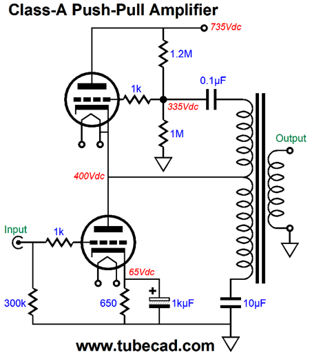
%20Push-Pull%20Class-A%20Amplifier.png)
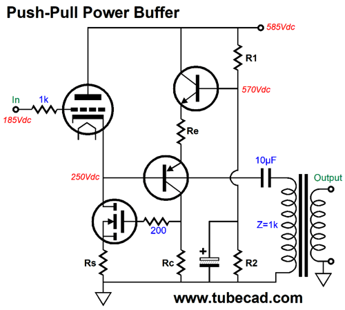
%20Push-Pull%20Class-A%20Buffer.png)
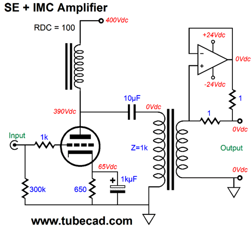
%20Push-Pull%20Class-A%20Amplifier.png)


| www.tubecad.com Copyright © 1999-2019 GlassWare All Rights Reserved |