| John Broskie's Guide to Tube Circuit Analysis & Design |
|
07 June 2019 (Updated 02 May 2020) Post 467
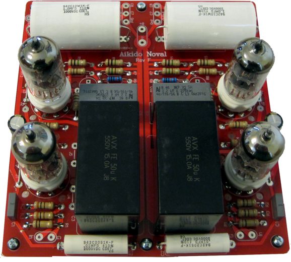
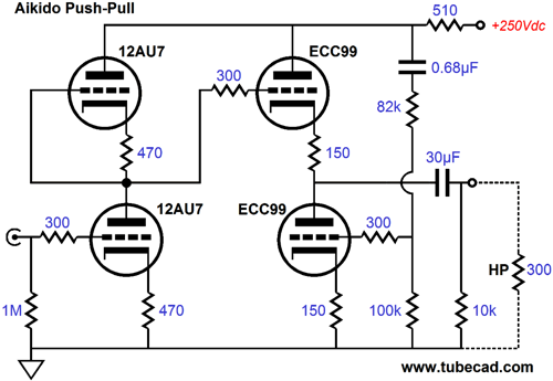
Aikido Novel Stereo Rev. F
The 510-ohm resistor makes the difference, as it forces push-pull output from the ECC99 output triodes. So why am I putting it back in Rev. F? It turns out that we can buy some dang big high-voltage polypropylene capacitors.
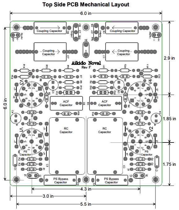
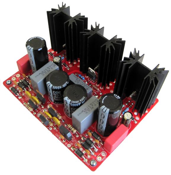
In the above image, you see the new Rev. F PCB holding two 120µF polypropylene RC capacitors, the big gray boxes. You also see tubular 33µF polypropylene output capacitors and ECC99 output tubes. In order to make everything fit, I made the PCBs half an inch longer, 6.5 inches versus Rev. E's 6 inches, which allows the big output capacitors to fit along with a small bypass capacitor and it gives the output tube more breathing room and better ventilation.
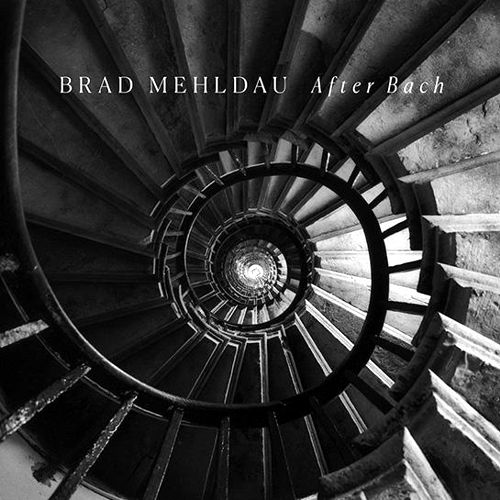
By the way, since I haven't fabricated the enclosure for the above PCB, I decided to test it as a line-stage amplifier, using only the 0.1µF CDE 1kV polypropylene bypass capacitor to couple to the rest of my system. So, how did it sound? Bad. I was shocked how bad. I was sure that I had screwed up somewhere, so I went hunting for my test equipment. When I returned to my listening room, the sound had improved dramatically. I thought to myself, "Please don't tell me it has something to do with break in." I hate the idea of "break in," as I am sure that usually it is we who break in, not the equipment. I want to hold a double blind test, wherein two identical pieces of equipment, save that one just came out of the box and the other was in constant use for a month, are compared. My bet is on no difference. Still... I was using new capacitors, new resistors, and new tubes. Moreover, I have seen the graphs showing that tubes DO undergo a big change in the first hours of their use, as the cathode coating must chemically settle down. Thus, we should give each new tube 24 hours of burn-in before evaluating it. Tube Rollers beware. Okay back to my story, I muted the sound and left the line stage powered, with the goal of returning in an hour. I couldn't wait that long. How long did I manage to hold out? An embarrassingly tiny 10 minutes. Dang, the sound was vastly better and everything measured correctly. Indeed, I could hear the sound improve before my ears; like a time-lapsed movie of a flower blossoming, the sound bloomed into sharper focus and warmer colors. I sat down and listened—and I couldn't get up. I had tons of work to do and my dogs needed emptying. I continued listening. I was glued in place. Part of the reason is found in this post's music recommendation, any album by Brad Mehldau. I was enthralled by his mastery. I had listened to his jazz-classical album, After Bach, only once before. It was pleasant, but not inspiring. Well, this time it inspired me greatly, so much so that at the conclusion of the last track, "Prayer for Healing," I wanted to stand and give a standing ovation.
The next test was to actually drive headphones, both 300-ohm Sennheiser HD650 and Grado 32-ohm and Audioquest Nighthawk 25-ohm headphones. I used a Tribute Audio output transformer, a kind gift from Pieter Treurniet, for both high and low impedance headphones, so the headphone amplifier will see a 1,200-ohm load. These headphone output transformers are amazing. Every time that I thought that I had perceived an audio signature, I was proved wrong, as the signature changed with the driving electronics. (If a gun were held to my head, I would say that the 300-ohm taps seem a bit brighter than the 32-ohm taps, but it would take a gun to make me even go that far.)
The power source was one of my PS-21 power supplies, which offers two low-voltage and one high-voltage regulators. This way each channel gets its own heater regulator; I set the high-voltage output to 250Vdc.
Very quickly, I ran into choices: too many choices. I found that using a high-mu input tube, such as the 12AT7 or 5751, seemed tilt the sound upwards to the highs; and a low-mu input tube, such as the 12AU7, seemed to tilt downward to the bass. Overall, I preferred the 12AU7, although the 5963 was a strong contender. I even tried a pair of NOS GE 5-Star 6072 tubes, with double mica spacers. The sound was neutral and if the tubes didn't command over $100 dollars each, I might have stuck with them. I needed to undo some of the bottom tilt with the 12AU7, so I replaced the 33µF output capacitor, which was four times too large in value for a 1200-ohm load, with a 10µF capacitor. The bass relented a bit, but the highs still seemed a tad attenuated. Fortunately, I have a lot of 10µF capacitors to choose from and I found the tiny Vishay black-box polypropylene capacitors provided the slight upward tilt I desired. So, are these the best coupling capacitors? No. In fact, the question is without merit, as there is no best capacitor, just as there is no best alcoholic drink, no best cheese, music genre, hair color, language, house style, loudspeaker, dog breed... I wanted to get the best sound, according to my taste, from my Audioquest Nighthawk headphones. Quite possibly, the Vishay 10µF capacitor would be the worst choice with different headphones and different tastes. Okay, how did the headphone amplifier sound? I like it, as it ever so genitally imparts that tube magic, where the sound takes on an effortless quality, with a touch of tube warmth and musical notes slowly die away into room ambiance. I often spend hours a day listening to headphones, so any hardness or brittleness in sound quickly wearies me. In fact, I use the length of time that I can listen to headphones as a measure of desirability. What is the point of owning flashy, crackling, bright headphones, if you cannot bear to hear them for more than ten minutes?
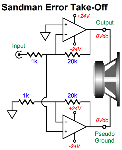
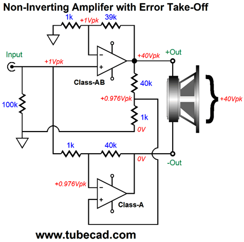
Error Take-Off
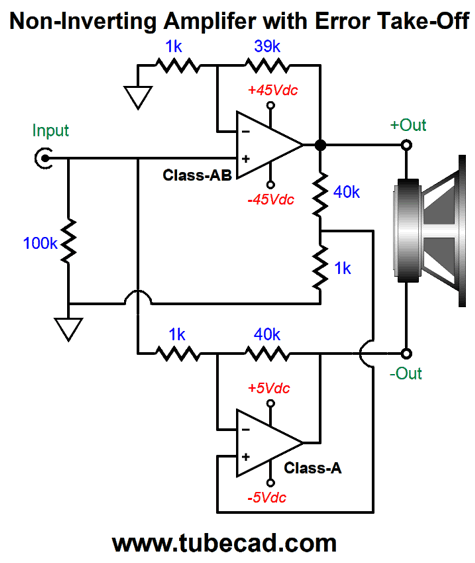
The result is that the distortion falls out of the equation, as the speaker is a fundamentally differential device. In other words, the speaker only responds to voltage differences; and if there's no voltage difference, then there's no speaker diaphragm movement. The dirty—but powerful—amplifier is configured in the inverting mode, unlike most power amplifiers; at its inverting input, the only signal present is the distortion divided by the gain set by the negative feedback resistors. (Actually, a tiny input signal must also be present, but the assumption is that the open-loop gain is so immensely great that we can ignore this minuscule signal, which is truly tiny with most inverting solid-state power amplifiers. With a tube-based amplifier, however, the open-loop gain might only be 12dB greater than the closed-loop gain; in other words, four times greater, so if 1Vpk is needed to drive the tube amplifier to full output with the feedback loop in place, then 0.25Vpk would appear at the inverting input. This explains why tube-based amplifiers fail to realize the same gain that a solid-state amplifier would, given the same negative feedback resistors. The small trace of clean input signal that appears at the inverting input, however, is no big deal, as it simply subtracts for the potential output voltage swing.) In the schematic shown above, we see both amplifiers running off the same power-supply rails. They needn't. We could run the bottom amplifier—or at least just its output stage—on far lower rail voltages, say +/-5Vdc. The bottom amplifier must be able to deliver the same peak output current swings that the top, dirty amplifier does. For example, a 100W amplifier delivers a peak voltage of 40V and a peak current swing of 5A into an 8-ohm load at 100W. Witha 4-ohm load, we get twice the power and twice the current, i.e. 200W and 10A. (This assumes that the amplifier's power supply and output stage are robust enough to sustain the higher current flow; many amplifiers are not, which explains specifications such as 100W at 8ohms, 160W at 4 ohms.) Here is the question that I asked myself, Couldn't we do error takeoff with a non-inverting dirty, but powerful amplifier? Couldn't we take an existing power amplifier and retrofit the error-take-off scheme external to the existing power amplifier? Indeed, we could, although it would be better to build an amplifier up with the scheme incorporated from the start.
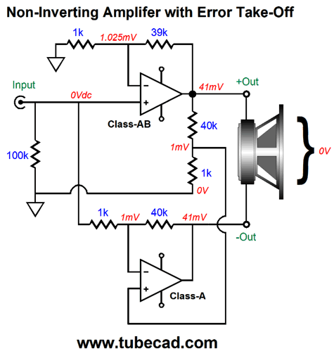
(Note the seeming redundancy of the feedback 1k and 39k resistors and the two-resistor voltage divider 1k and 40k resistors. Why not just use the first set of resistors in the feedback loop? In theory, we could, but then this error-take-off scheme could not be easily retrofitted to an existing amplifier. In addition, that arangement would subtract the input signal from the output signal. In other words, the bottom amplifier would put out the same signal as the input signal to the top amplifier.) The top amplifier runs in class-AB and with +/-45V power-supply rail voltages. The bottom amplifier operates in strict, pure class-A, either in push-pull or single-ended, and runs under puny +/-5V power-supply rail voltages. Where the top amplifier idles thinly, the bottom amplifier idles heavily. How heavily? Let's say that the top amplifier puts out 100W into an 8-ohm load, which implies a peak voltage swing of 40V and peak current swing of 5A. As the bottom amplifier runs in strict class-A, its output stage (OPS) idle current must be at least half of the 5A with a push-pull output stage. I would round up to 3A, which against the +/-5V power-supply rail voltages equals 30W of heat at idle. With a single-ended OPS, the idle current must be twice as high for the bottom amplifier. Moreover, if 4-ohm loudspeakers are driven, we must double the current flow again. In contrast, the top amplifier might run only 100mA through its output stage, which results in only 9W of heat dissipation at idle. Remember, the bottom amplifier only has to swing at its output whatever distortion signal the top amplifier produces. Think of it as a virtual-ground plus. The bottom amplifier must, however, deliver the same current swings as the top amplifier; for example, in the 100W example, it must swing a 5A peak swing. While the bottom amplifier's output stage runs under wimpy +/-5V power-supply rails, its input and driver (VAS) stages can and should attach to the top amplifier's +/-45V power-supply rails. Indeed, we could easily add positive and negative voltage regulators to bring these voltages down to +/-24Vdc for the bottom amplifier's use. Okay, let's examine how this error-takeoff scheme works. We will begin by assuming that the top amplifier produces a fairly big 41mV DC offset at its output.
The 41mVdc voltage is then reduced to 1mVdc by the two-resistor voltage divider at the top amplifier's output and ground; and this 1mV voltage becomes the bottom amplifier's input signal, which it amplifies by 41-fold, so 41mVdc appears at the bottom amplifier's output. The loudspeaker sees the same 41mVdc at both its terminals, which it ignores entirely. The voltage at each terminal could have been 41Vdc or 410Vdc or 4,100Vdc, but the loudspeaker would remain supremely indifferent, as the differential voltage would still be zero. Let's assume that the top amplifier is perfect, producing no distortion. At full output, we would see the following.
The top amplifier delivers 40Vpk at its output, while the bottom delivers 0V, so the speaker sees a 40Vpk differential, which implies 100W. So it looks like this error-takeoff scheme costs us 5% of our potential power. What if the top amplifier can only put out 38Vpk?
The top amplifier's clipped output waveforms are a form of distortion and the bottom amplifier will swing negatively to achieve the full, unclipped, distortion-free output across the loudspeaker.
This SPICE-generated graph reveals how the top amplifier's clipping is erased by the bottom amplifier. Of course, once the bottom amplifier clips, the distortion can no longer be nulled.
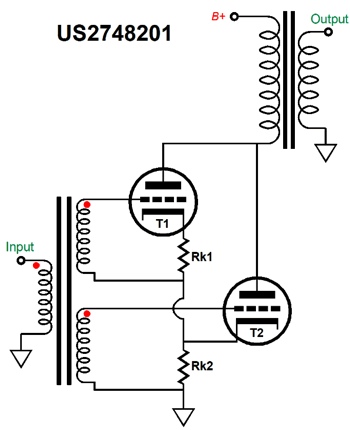
US Patent 2,748,201
As patent schematics go, this is a fairly easy one to understand. Nonetheless, I have redrawn it here:
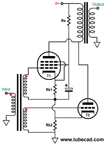
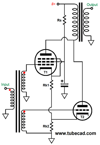
The top triode, T1, is the primary output device, while bottom triode, T2, is the distortion clean up device. The bottom triode monitors the voltage drop across cathode resistor Rk2 and compares this voltage to the input signal, altering its current flow to correct the mismatch. Since both triodes entire current flows sum in the output transformer's primary, the result is distortion reduction. A key feature to this design is that the top triode is effectively floating, as it sees no direct connection to ground. In addition, note that its input signal is reference to the bottom of cathode resistor Rk1, not ground. The result of being floating is that the top triode's impedance goes up substantially. For example, the impedance presented at the bottom of cathode resistor Rk1 is equal to rp + muRk1, not the low impedance we would expect from what looks like a cathode follower; but the top triode is not configured as a cathode follower, but as a grounded-cathode amplifier, a floating grounded-cathode amplifier. Indeed, we should view the top triode as largely constituting a voltage-to-current converter circuit. In contrast, the bottom triode, T2, presents a relatively low impedance. Moreover, it doesn't have to fight the top triode; instead, the bottom triode can alter the top triode's plate voltage by varying its current conduction as it strives to undo the top triode's distortion. Since we want the top triode to present a high impedance, why not use an extrinsically high impedance device, such as a pentode or MOSFET?
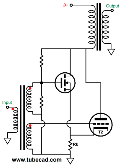
While this would probably work well, note that the pentode's screen resistor, Rs, is effectively in AC parallel with the bottom cathode resistor, Rk2. In other words, the pentode is free-floating as we might like. Actually, I don't see why we cannot use the following configuration.
The pentode's signal source is now ground referenced and screen capacitor terminates into ground. Where we might run into trouble is that the pentode might not require as high a cathode-bias voltage as the triode. If we replace the pentode with a MOSFET, then the MOSFET will require a positive gate bias voltage.
The two-resistor voltage divider establishes the bias voltage for the MOSFET and cathode resistor biases the triode. In actual practice, we run into the problem of the cathode resistor being too high in value. Here is what will happen: assuming a B+ voltage of over 300V, the triode will require an extremely high cathode voltage to limit the triode's current conduction; this high-valued cathode resistor will subtract from the MOSFET's transconductance, excessively. The workaround is to use fixed-bias on the triode. Okay, how well does this distortion-reduction scheme work? In SPICE simulations, I found that it does indeed reduce THD, but it also brings problems. While the distortion is reduced, the 2nd harmonic gets the greatest reduction, which undoes some of the single-ended flavor. Worse, this scheme presented a much higher output impedance. In other words, the only plate resistance is that offered is by the error-reducing triode, which would probably be a small triode that can withstand high-voltages, such as the 6SN7, 12B4, and ECC99, all of which present a much higher plate resistance than a 300B. In fact, I found it impossible to realize the same power output or lower distortion than some of my super-triode efforts.
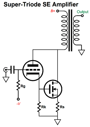
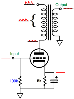
Single-Ended Super-Triode Amplifier
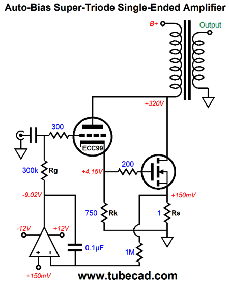
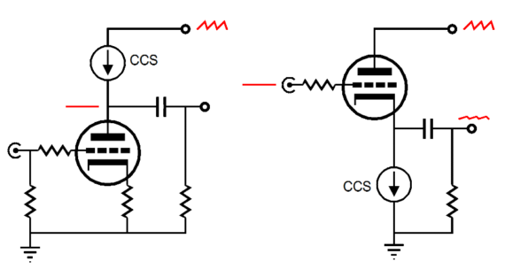
The triode is capacitor coupled to the input signal, as we need to apply a negative bias voltage to its grid. The MOSFET's source resistor should be low in value, say no more than 1 ohm. Here is an example that uses an ECC99 triode.
The triode draws 5.5mA, while the MOSFET draws 154mA at idle. The output transformer primary sees the combined current flow from both devices. We could use a DC servo to auto-bias the MOSFET through the triode's cathode voltage.
The OpAmp strives to maintain equal voltages at both its inputs. If the MOSFET draws too much current, the voltage drop across the source resistor will rise, which will prompt the OpAmp's output voltage to fall, causing the triode to lessen its current conduction, which in turn will reduce the MOSFET's conduction, bringing it back in in line with the desired DC voltage. Since this output stage runs in strict class-A, the AC signal imposed upon the source resistor will average to the DC voltage over time. Okay, what's not to like here? One hassle is the need for a negative power-supply rail voltage. The workaround would be to forgo the negative rail and move the input coupling capacitor to in between the triode and MOSFET.
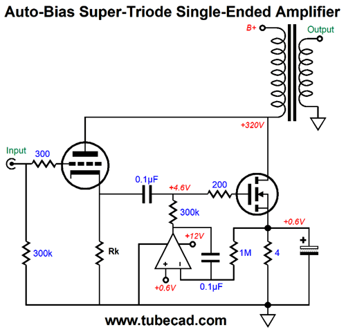
Now, the triode is DC coupled to the input signal and the MOSFET gets the DC servo. This is a much safer approach, as the MOSFET is protected from the inserting of the wrong tube in the socket, say an EL84 instead of the expected ECC99. In addition, the MOSFET can come up to idle current independent of the triode. The only problem is the high source resistor value and the consequent need for a large-valued bypass capacitor. We must use a large-valued source resistor, as most OpAmps cannot tolerate a signal voltage so close to its negative power-supply-rail voltage. (Avoid OpAmps with transistor input stage, using FET-based input stages instead.) One workaround would be to replace the source resistor with a diode.
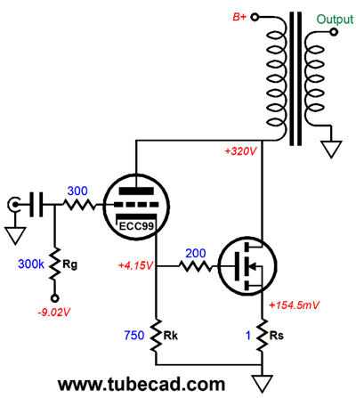
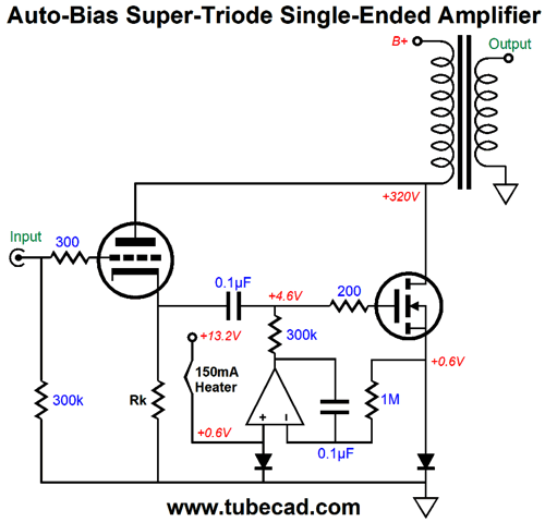
Both diodes are the same type and both see the same current flow, which establishes equal voltage drops across each. We use a 150mA heater element to provide the needed current flow through the left diode, which results in the MOSFET drawing 150mA at idle. Note the 13.2V power supply voltage, which the heater attaches to and which can power the OpAmp. What if you prefer to use a different triode, say an ECC99, whose heater draws 400mA, not 150mA? The workaround is first find the difference in current flow, which in this example is 250mA. Next we divide the diode's voltage drop of 0.6V by the difference, i.e. 0.25A, and we get 2.4 ohms as the the needed resistor value to shunt the diode the heater terminates into; the resistor can be a 1/2W or 1W type. Okay, let's flesh out this design with part values.
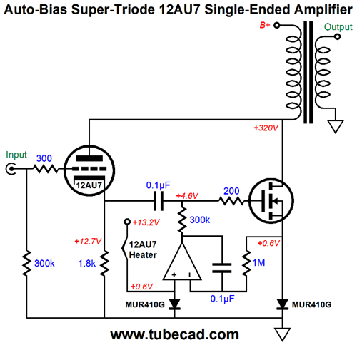
The 12AU7 provides the cathode follower triode and the needed heater element. Since we get two triodes in a 12AU7 tube, we can use the other triode in the input stage.
This amplifier works beautifully in SPICE, but it harbors an unseen problem. The super-triode configuration results in a truly low output impedance, about 20 ohms, so the output stage's PSRR suffers, as the output transformer's primary sees almost all of the B+ voltage ripple. In other words, the lower the plate resistance, the worse the PSRR.
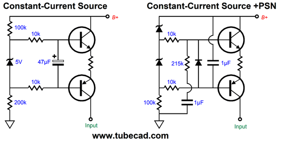
The workaround would be to inject some Aikido mojo. What we need is a small portion of the ripple to appear at the super-triode input, but inverted in phase. Long ago, I created a special constant-current source that purposely performed this inverted ripple signal function.
The circuit on the left is a high-voltage constant-current source. It uses both NPN and PNP high-voltage transistors and the 5V zener to establish a fixed current flow. The constant-current source on the right, uses the extra capacitor and resistor to inject some anti-phase current variation due to ripple upon its output current. I got this circuit to work in SPICE simulations, but I was bothered by its complexity. It is easy to make complex and effective, but simple and effective is difficult—if not close to impossible. As I stared at the circuit, I saw a much simpler solution.
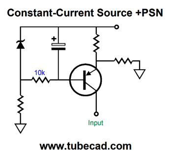
This constant-current source also injects an inverted reaction to the power-supply noise at its output. The 280k resistor sees 100% of the ripple and its current flow varies as a result, which adds and subtracts in anti-phase to the constant-current source current flow. Okay, let's put it all together.
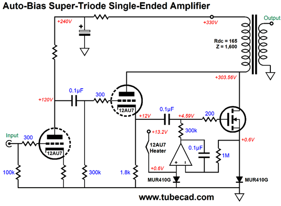
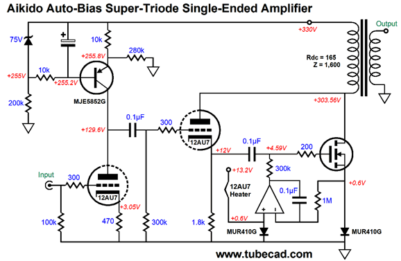
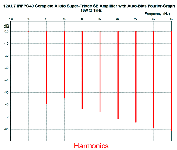
Dang simple, isn't it? This super-triode single-ended power amplifier uses just one tube per channel and delivers 16W with a One-Electron UBT-1 output transformer and relatively low B+ voltage of only 330Vdc, which we can create by rectifying a 240Vac secondary. Here is the SPICE-generated Fourier graph for full output, 16W. (By the way, I included the UBT-1's primary DCR in my simulations.)
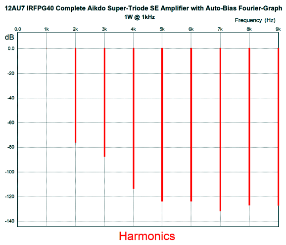
The THD is 0.24%. Here is the graph for 1W of output.
The THD has fallen to less than 0.02%. Amazingly low. The plate impedance of the Super-Triode combo is 20 ohms, which divided by the output transformer's impedance ratio of 200:1 become insanely low at the secondary. In fact, the Primary's and secondary's DRC are likely to overwhelm. The PSRR is across the primary is -40dB, which divided by the output transformer's winding ratio of 14:1 improves dramatically. Okay, even if reality is ten times worse, it's still vastly better than 99.9% of single-ended amplifiers. If you have read this far, then you are the type of tube-loving audiophile who doesn't stop at What an amplifier does, but insists on asking How does it do it? The secret is found in the MOFET retaining almost all of its transconductance, due to the use of the MUR410G rectifiers. These ultra-fast rectifiers present a very low effective resistance, which helps the MOSFET preserve its transconductance. The formula for the decrease in a MOSFET's gm because of an unbypassed source resistor is: gm' = gm / (1 + gmRs) As you can see, the greater the source resistor's value, the lower the effective transconductance. The 12AU7 makes use of this huge amount of transconductance to achieve Super-Triode performance.
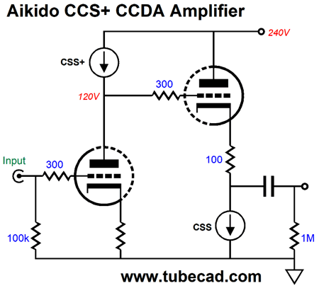
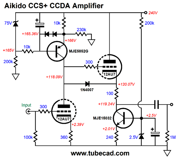
Aikido CSS+ CCDA Line-Stage Amplifier
Well, we can undo the cathode follower's leaking of the power-supply noise at its output by feeding its grid 1/mu worth of power-supply noise, but phase inverted. In other words, when the ripple swings up, the grid swings down by 1/mu, so the cathode becomes indifferent to the ripple, as a triode's amplification factor, mu, is a measure of the relative effectiveness of the grid over the plate in controlling the triode's current flow. For example, if the mu is 10 and the plate voltage is increased by 10V, we can counter the triode's increase in current flow by reducing the grid voltage by 1V.
This is the general idea: a special constant-current source plus (CCS+) adds some anti-phase ripple and the PSRR is greatly enhanced.
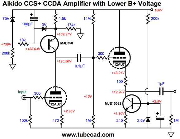
The 12AU7 input triode realizes a gain equal to its mu, as its plate is loaded by the constant-current source. The 12AU7-based cathode follower is loaded at its cathode by another constant-current source. The diode is a safety device that protects the cathode follower triode at turn-on. The 3V zener protects the PNP transistor from seeing too great a base-to-emitter voltage. All in all, not a bad line-stage amplifier. If we are willing to tolerate an internal coupling capacitor, we could run a far lower B+ voltage.
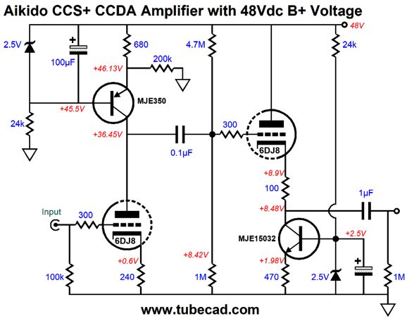
In spite of the lower B+ voltage, the bottom triode sees a greater cathode-to-plate voltage. We could even use a ridiculously low B+ voltage, say 48Vdc, with a 6DJ8.
We want the cathode follower to get as much cathode-to-plate voltage as possible, as we want the highest current flow possible without running into positive grid voltages. With almost 40 volts, this cathode follower draws a little over 4mA, an impressive amount considering the 48Vdc B+ voltage. One potential problem here is the high gain, unless that was your goal. With the CCS+ loading of the input triode, we get a gain roughly equal to the triode's amplification factor (mu), which is about 31 with the 6DJ8. of course, if we sought more gain, for example in a two-stage phono preamp, the +30dB of gain would come in handy, as we would lose 20dB with a passive RIAA equalization network, bringing the total gain to +40dB for a phono preamp. Not bad considering the low B+ voltage. This circuit is even simpler than the previous one, as we used 2.5V voltage reference in place of the 75V zener. The assumption here is that an IC voltage references, such as the LM185-2.5 or TL431, are used, which are far quieter than zeners. In fact, the 2.5V voltage means that we can lose the safety diodes or zener, as the base-to-emitter voltage cannot exceed 2.5V. By the way, I am sure that some of you are wondering why I included the 100-ohm cathode resistor on the cathode follower output. In general, the cathode follower should see some pure resistance before it encounters capacitance. Nonetheless, the output impedance would only come in at a little over 200 ohms.
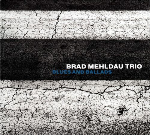
Music Recommendation: Any Album by Brad Mehldau His albums are well served by Tidal, as it offers 22 of them.
I recommend starting with his album, Blues and Ballads, but really all are worth hearing. The one album that did disappoint me at first was his album, After Bach, which is not a jazzy cover of Bach hits; instead, it is an improvisational interpretation of Bach works. Yesterday, I listen to this album again and I found myself finally getting it—and there is much to get.
England's The Guardian offers an insightful review of this album. //JRB
User Guides for GlassWare Software
For those of you who still have old computers running Windows XP (32-bit) or any other Windows 32-bit OS, I have setup the download availability of my old old standards: Tube CAD, SE Amp CAD, and Audio Gadgets. The downloads are at the GlassWare-Yahoo store and the price is only $9.95 for each program. http://glass-ware.stores.yahoo.net/adsoffromgla.html So many have asked that I had to do it. WARNING: THESE THREE PROGRAMS WILL NOT RUN UNDER VISTA 64-Bit or WINDOWS 7 & 8 or any other 64-bit OS. I do plan on remaking all of these programs into 64-bit versions, but it will be a huge ordeal, as programming requires vast chunks of noise-free time, something very rare with children running about. Ideally, I would love to come out with versions that run on iPads and Android-OS tablets.
//JRB
|
|
John Gives
Special Thanks to the Special 85!
I am truly stunned and appreciative of their support. In addition I want to thank the following patrons:
All of your support makes a big difference. I would love to arrive at the point where creating my posts was my top priority of the day, not something that I have to steal time from other obligations to do. The more support I get, the higher up these posts move up in deserving attention. Only those who have produced a technical white paper or written an article on electronics know just how much time and effort is required to produce one of my posts, as novel circuits must be created, SPICE simulations must be run, schematics must be drawn, and thousands of words must be written. If you have been reading my posts, you know that my lifetime goal is reaching post 1,000. I have 533 more to go. My second goal is to gather 1,000 patrons. I have 915 patrons to go. Help me get there.
Only $12.95 TCJ My-Stock DB
Version 2 Improvements *User definable Download for www.glass-ware.com |
||


| www.tubecad.com Copyright © 1999-2019 GlassWare All Rights Reserved |