| John Broskie's Guide to Tube Circuit Analysis & Design |
16 Aug 2019 (Updated Aug 25 2019) Post 474
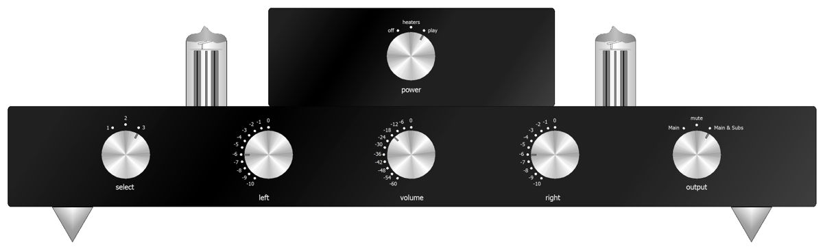
Project Update
Why not? Summers are tough due to my teenage kids not being in school. If you are not a modern parent, this may not make sense; if you are one, however, you know how much limo service modern life demands of you. (Today, half my day was spent driving my kids in opposite directions about town.) Nonetheless, I still like the primary idea behind the project and I already own the two painted chassis. All that remains is the hard work of drilling and punching the boxes. (By the way, I have discovered that when the logic, the logos, the underlining wedding between function and form, the aim, end, goal, intention, objective, and purpose of the project is clear to me, the project almost builds itself. In contrast, when the logic lags or the design dawdles, I require superhuman resolve to finish the project.) Peter asked if I didn't have it backwards or wrong: why was I giving the subwoofer amplifiers the preferred cathode-follower outputs and giving the main power amplifiers the lessor grounded-cathode amplifier outputs?
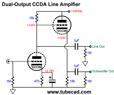
My aim was to play with a minimalist line-stage amplifier that held one triode per channel in a grounded-cathode amplifier configuration; but with the added subtlety of giving each tube its own regulated heater power supply. The cathode follower stage was something of a bonus, as its role was to ensure constant-current draw, as the cathode follower works in voltage phase with the input grounded-cathode amplifier, but in anti-current phase with it. Since I own self-powered subwoofers, I put the cathode follower outputs to work driving the solid-state power amplifiers. Here is the problem with giving the subwoofer amplifiers the grounded-cathode amplifier outputs: if the subwoofer amplifiers are located within the subwoofers, not just a few feet away on your rack next to your line-stage amplifier, then long lengths of interconnect will present a high-capacitance load to the grounded-cathode amplifier and drag down its high-frequency response, which will then get passed on to the cathode follower, whose output will also be high-frequency limited. In contrast, when the cathode followers drive the long interconnects, the grounded-cathode amplifier knows nothing about the high capacitance the cables present.
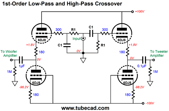
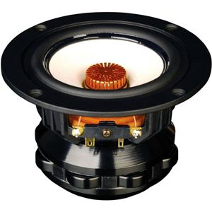
Active Crossovers (By the way, almost 15 years ago, while attending the CES, I heard some amazing loudspeakers that held a single small 5-inch fullrange, and which cost $1300 the pair. They were beautifully finished in leather covered cabinets, the same leather that was used in restoring Ferrari cars, as that is where the maker acquired the leather. The loudspeaker's designer told me that he bought several hundred of the $20 fullrange drivers and thoroughly tested each one, culling all but a third. The leftover two thirds he sold to an auto-stereo shop. He then treated each driver's cone with stripes of hard glue, spiraling from the center, clockwise, then counter clockwise. After the drivers had dried, he tested them again and collected matched pairs, from which he built pairs of loudspeakers. The result was well worth the $1300 price-tag, as the imaging was shockingly holographic. In general, tiny loudspeakers image well, but these brought imaging up to a new standard.) Once we add another driver, however, we need a crossover, either passive or active. After coming up with my passive series-shunt, phase-flat crossover, I set about creating an active version for use in a tri-ammped loudspeaker systems. I have yet to succeed. The problem seems a bit more daunting that I first imagined. More work is needed. One goal I sought was that either vacuum tubes or OpAmps could be used, but with the important stipulation that only resistors and capacitors but no inductors were used to set the crossover frequencies, as the inductors would have to be huge in value. For example, a 1,592mH inductor is needed for a simple low-pass 1kHz crossover with a 10k resistor. In contrast, the needed capacitor is only 0.0159µF for a high-pass crossover with a 10k resistor. If the crossover frequency had been a decade lower, 100Hz, the inductor would need to be 15.92H in value, along with a still useable 0.159µF capacitor. At radio frequencies, using inductors makes more sense, but not at audio frequencies. Here is the exact same functionality with no inductors. If we used 100k resistors, the capacitor values would reduce by tenfold. If we want to use tubes, not OpAmps, the circuit would be simple enough.
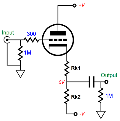
The bipolar power supply makes DC coupling at the input possible, saving us the need for an input coupling capacitor. In addition, the bipolar power supply allows for an enhanced PSRR, as long as the two power-supply rails contain the same ripple amplitude, but opposite ripple phase.
The formula for finding Rk1's value is simple. Rk1 = (Rk2 - rp)/(mu + 1) Where rp is the triode's plate resistance and mu is its amplification factor. This formula delivers the needed value for Rk1 so that the resistances above and below the output equal, so the bipolar power supply ripple nulls at the nexus, just a two-resistor voltage divider would.
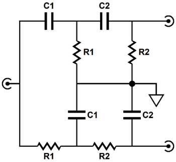
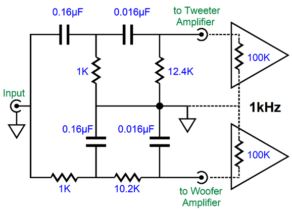
What if we want a 2nd-order crossover, rather than a 1st-order? The only 2nd-order alignment that delivers a flat frequency response is the Linkwitz-Riley (aka Butterworth²), which yields a -6dB output from the drivers at the crossover frequency, which in turn then sums to unity. Making the two-way crossover for bi-ampping is fairly easy, even without active devices, such as tubes, transistors, OpAmps. Here is an example.
The Linkwitz-Riley 2nd-order crossover results in -6dB attenuation for both the woofer and tweeter at the crossover frequency and a Q of 0.5, which the above passive circuit will deliver. The rough math is fairly simple. C1 = 159155/R1/Frequency Where C1 and C2 are in µF. This gets us close to the right values. Here is what SPICE simulations revealed to be the best readily available part values for a 1kHz crossover.
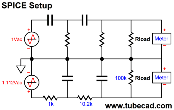
The assumption is that the amplifiers' input impedance is 100k. Note that low-pass filter suffers from an insertion loss, which the high-pass filter avoids. This not a deal breaker, as the two speaker drivers are not likely to share the same efficiency, so some adjustments to the amplifier will be needed. The low-pass attenuation will, however, prove to be a hassle in SPICE simulations. The workaround is to use two AC voltage sources, with the low-pass portion getting the AC voltage source with enough extra signal to undo the attenuation.
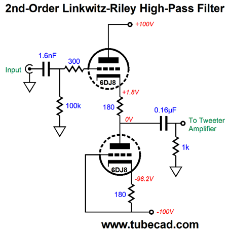
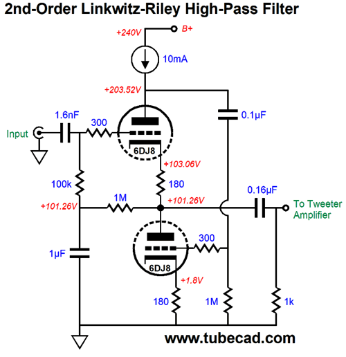
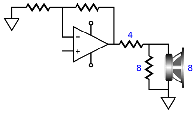
How did I come up with 1.112Vac? We add 1k to 10.2k and 100k, which yields 111.2k; then we divide 111.2k by 100k and get 1.112. In other words, we are undoing the attenuation the low-pass filter sees. By the way, whenever the topic of bi-ampping comes up, I must warn about the need for a safety coupling capacitor for the tweeter. Never forget that a tweeter is a delicate device. Now imagine a faulty interconnect or someone accidentally knocks the RCA plug half way out of the tweeter amplifier's input jack, breaking the ground connection, provoking a monstrous hum. Smoke! No tweeter can survive full output at 50Hz or 60Hz. Thus, for safety's sake, use a crossover capacitor that kicks in at a frequency ten times lower than the tweeter crossover frequency. The only exception might be loudspeaker with built-in power amplifier, as the internal tweeter amplifier will see the 60Hz hum only after it's has been attenuated by the active crossover. Additionally, ribbon tweeters that hold internal step-down transformers present input DC resistances in the milliohms range, which can cause solid-state output stages to blow fuses or at least overheat due to amplifier DC offsets of only a few millivolts. Once again, a coupling capacitor is the solution. On the other hand, transformer-coupled power amplifier seldom present DC offsets. (And if they do, seldom can they deliver more than a milliamp or two of current.) For the most part, active crossovers sidestep the problem of amplifier input impedance variations. Here is an example of an active high-pass, 2nd-order Linkwitz-Riley 1kHz crossover that uses the input and output coupling capacitors as part of the filter design.
Note the 1k resistor. This crazy low resistor value was chosen so the amplifier's impedance, usually between 20k to 100K with 47k being an old standard value, would prove less important. Another approach would be to include a potentiometer in the design, which would allow compensating for a range of amplifier input impedances and would allow us output to use a smaller-valued filter capacitor, just 0.016 µF, rather than 0.16µF.
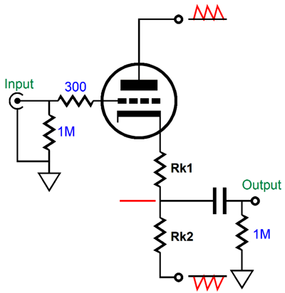
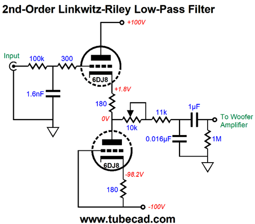
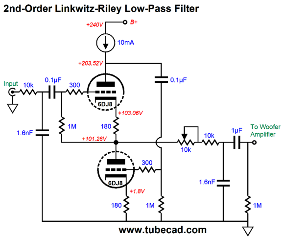
Note the 10k potentiometer. At one extreme, we can use this filter with a power amplifier with an input impedance of 20k; at the other extreme, a 100k impedance. Since I know that many tube-loving folk have zero interest in any tube circuit that uses a bipolar power supply, here is the same low-pass 2nd-order 1kHz Linkwitz-Riley crossover with a mono-polar power supply.
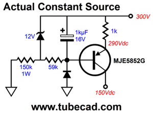
The underlining tube circuit is the White cathode follower, but with a difference—namely, in place of a plate resistor we find a constant-current source. The constant-current source undoes all the pushing and pulling of the top triode, which runs in strict constant current, due to the constant-current source; instead, the bottom triode varies its current conduction. In other words, this circuit runs as a single-ended buffer, not a push-pull one, so the constant-current source sets the maximum output current swing to its own idle current draw. In contrast, a White cathode follower, with an optimal plate resistor value for the intended load impedance, will deliver up to twice the idle current flow as its maximum output current swing. On the other hand, the constant-current source ensures near unity-gain, fantastic PSRR, and an amazingly low output impedance. How low? With the 6DJ8 tube and the unbypassed cathode resistors, the output impedance was a tad less than 10 ohms in SPICE simulations. The formula, with bypassed cathode resistors, is roughly: Zo = rp/mu² With unbypassed cathode resistors, Zo = (rp + (mu +1)Rk) / mu² The 6DJ8 SPICE model exhibits a mu of about 31, not the tube manual's 33, so the simulation results are in line with the formula. The constant-current source also shields the triodes from the B+ voltage ripple. The only downside to the constant-current source is that you have to make your own, as high-voltage constant-current sources with preset current draws are not sold at Mouser or Digikey.
Another possible hassle with using a constant-current source is that the voltage relationships might not divide evenly into three thirds. Why? The constant-current source works best when working into a fixed low resistance, whereas in this White-cathode-follower circuit the top triode's plate impedance is insanely high, about a third of a megaohm. What saves the day is the auto-biasing of the top triode through its cathode resistor and the 1M resistor. If a fixed bias voltage were used instead, we would be sure to run into headaches. In contrast, a large-valued inductor or one of my compliant-constant-current sources or, even, a 10k plate resistor would sidestep this potential problem. Still, I would never cheat the constant-current source of voltage. In other words, I would never hook up the above circuit to a B+ voltage of just 220Vdc. I will work in SPICE, but probably not in reality, as the two real triodes are lucky if they match each other within 5%, whereas the SPICE triodes match perfectly. Okay, how do we make a high-pass version of this active filter?
We use both the input and output coupling capacitors as part of the filter. The input 1.6nF (0.0016µF) coupling capacitor and the 100k grid resistor define a first-order high-pass filter at 1kHz, as do the 0.16µF capacitor and 1k load resistor. Each 1st-order filter imposes a -3dB dip at the crossover frequency, so they combine to -6dB; each filter also results in 45 degrees of phase shift at the crossover frequency, which combine to 90 degrees, creating a total of 180 degrees between low-pass and high-pass filters, which explains why the tweeter's phase must be reversed to prevent a deep null at the crossover frequency. The shunting 1µF capacitor to ground provides an AC path to ground for the 100k filter resistor.
Third-Order Active Crossovers
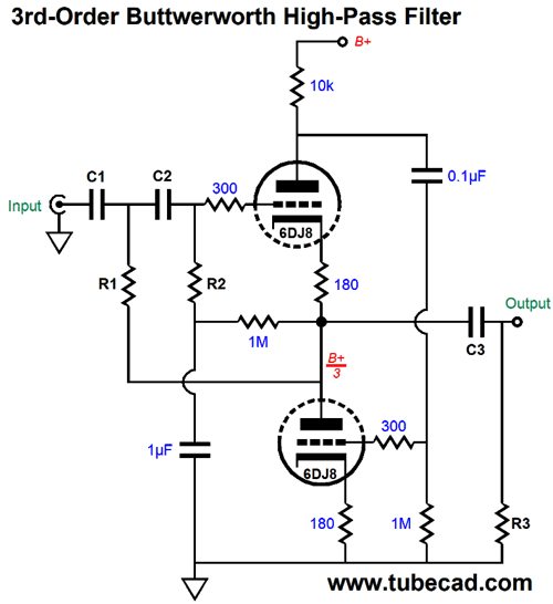
Effectively, what we have here is a 2nd-order Salen-Key filter with a Q of 1 followed by a passive 1st-order filter with a Q of 0.707; both Qs are then multiplied against each other, resulting in a final Q of 0.707. The math is super simple, fortunately. C1 = C2 Where all the capacitor values are in µF. We purposely choose a very low value for R3, so that the tweeter's power amplifier input impedance does not throw off the crossover frequency. Alternatively, we can use the amplifier's input impedance as part of the filter. For example, say that the power amplifier's input resistance is 20k, then we can make R3 equal to 20k, which effectively reduces R3's value to 10k, as R3 is in parallel with the amplifier's input impedance. The 1M capacitor provides an AC "ground" for R2. Note that a 10k plate resistor was used in place of the constant-current source. Why? If the B+ voltage is well filtered or regulated, the plate resistor works almost as well as the constant-current source in this circuit. Making a low-pass version will require a bit more work.
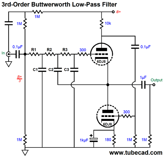
We must give the top triode a DC reference. The easiest way is to use a voltage divider made up of resistors. In this schematic, the three 1M resistors in series that bridge the B+ voltage to ground deliver one third of the B+ voltage to the top triode's grid. The reason we use three 1M resistors in place of just two is that we want to use the topmost 1M as an RC filter with the capacitor to ground, ensuring improved PSRR. Note that the top triode doesn't get a cathode resistor and the bottom triode's cathode resistor is bypassed by a large value capacitor. Unlike the high-pass version, this filter is entirely an active 3rd-order design. The math is based on the √2, 2.5 √2, and √2/3.5 capacitor ratios. R1 = R2 = R3 Where all the capacitor values are in µF. The output coupling capacitor need only be large enough to provide a sufficiently low-frequency cutoff frequency, say 10Hz or 20Hz. Although the 3rd-order filter provides a steep slope, it is not phase flat.
Note the tone burst does not come out cleanly from the two speakers' acoustic sum.
Symmetrical and Asymmetrical Phase-Flat Crossovers
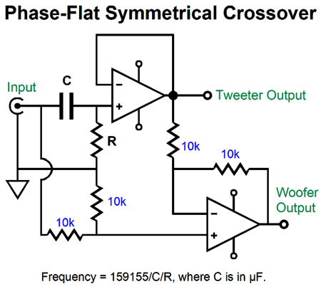
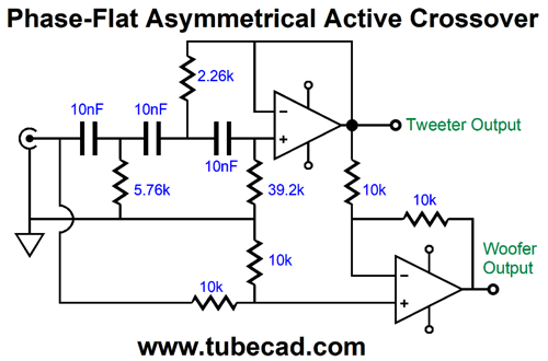
The bottom OpAmp compares the high-pass output to the input signal and creates the missing low-pass filter function at its output. Why bother? Let's say you are buying $800 exotic coupling capacitors made from illegal whale oil and rare platinum foil, buying a total of four $800 capacitors might be deemed excessive. Another reason we might opt for this design is that it allows us to make an easy variable-frequency crossover.
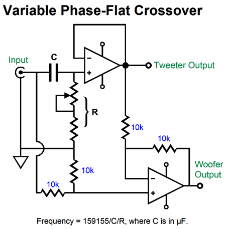
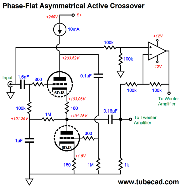
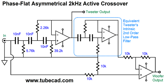
The potentiometer, which could and probably should be replaced by a linear stepped-attenuator, allows us to move the crossover frequency up and down, without having to switch between many capacitor values. I can see how this circuit might greatly help a loudspeaker designer, as he could quickly find the optimal crossover frequency and then go about making a passive crossover based on the frequency. Okay, now that you are familiar with the logic behind this active crossover, let's look at an asymmetrical crossover that cuts off the tweeter's signal with a 2nd-order slope, but attenuates the woofer's input signal with a gentle 1st-order slope. Let's make it more interesting by using a tube-based high-pass filter with an OpAmp-based differential amplifier.
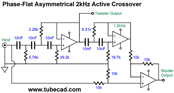
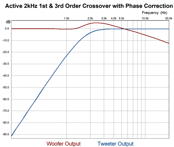
The 1kHz crossover's combined outputs results in flat frequency and phase plots, amazingly enough. Actually, this makes sense due the bottom OpAmp being configured as a differential amplifier whose output must perfectly complement the 2nd-order filter's output. In other words, the differential amplifier's output is what is missing from the 2nd-order filter's output to make a flat frequency response and flat phase plot. Okay, we now move on to a 3rd-order asymmetrical crossover, but with a 2kHz crossover frequency.
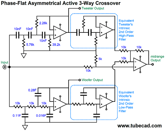
I have seen this setup used with subwoofers and satellite loudspeakers, where the subwoofer gets a 3rd-order low-pass filter and the satellite gets the differential amplifier's output. In contrast, the values chosen for the above schematic set a crossover frequency of 2kHz. Why? I have been intrigued by ribbon tweeters and Heil AMT tweeters, both of which can be crossed over at 2kHz. The ear is most sensitive between 3kHz and 3.5kHz to phase aberrations, so crossing over either below or above this range of frequencies is a good idea. Mind you, the woofer needs to have a far higher bandwidth due to the shallow crossover slope it sees. I recommend using a fullrange driver. Okay, the big question to ask your self is: Sure this scheme might be mathematically sound and pass SPICE simulations, but would it actually yield flat frequency response and flat phase response with real speaker drivers? The quick answer is no, it wouldn't. Why not? First, if any normal woofer were used, its bandwidth would fall far short of what is required. Second, all tweeters exhibit a mechanical resonance at some frequency below their nominal cutoff frequency. For example, most 1-inch dome tweeters have a resonant frequency that falls between 600HZ to 1200Hz, below which the tweeter acts as if it were attached to 2nd-order crossover at that resonant frequency. The late, great Siegfried Linkwitz understood this and compensated for the tweeter's implicit 2nd-order high-pass filter in his active crossover designs. Well, we can do the same.
Here we see the tweeter amplifier getting its input signal from the 3rd-order high-pass filter, while the differential amplifier sees an additional 2nd-order high-pass filter tuned the tweeter's resonant frequency. The ribbon tweeter that caught my attention presents a resonant frequency of 1200Hz; thus, here are the crossover values needed for a 2kHz crossover that compensates for the tweeter's implicit high-pass 1200Hz filter.
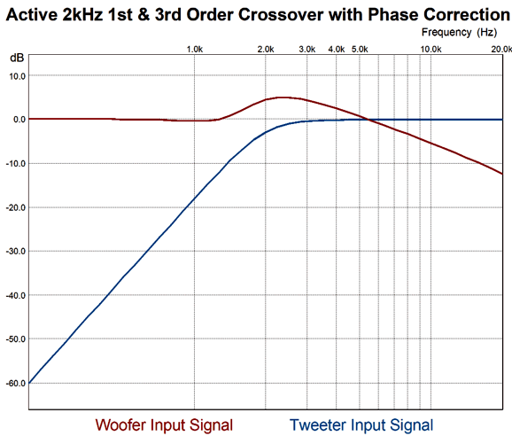
Unfortunately, I don't remember the tweeter's Qts, which the 2nd-order high-pass filter should be tuned to, so I assumed 0.7 as its Qts. Let's look at the signal that is presented to the woofer and tweeter amplifiers.
Note how the woofer amplifier's output at 20kHz is only -12dB down, while the tweeter's amplifier output is down -60dB at 200Hz. That's asymmetrical. Now, let's look at what the drivers actually put out. (The assumption is that the woofer is actually closer to being a fullrange driver; perhaps it's an electrostatic panel that is being crossed over to a dipole ribbon tweeter.)
The tweeter's output is far more steeply attenuated at 200Hz due to its own implicit 2nd-order filter. What if we add a real woofer to the mix, so we can tri-amp the loudspeaker? This would greatly unload the fullrange driver and would deliver far deeper bass response. By choosing 200Hz as the bottom crossover frequency, we end up cutting up 20Hz to 20kHz bandwidth into three equal portions, as 200Hz/20Hz = 2kHz/200Hz = 20kHz/2kHz. Great, how do we proceed?
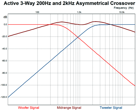
We have applied the same differential amplifier trick to the bass-frequency crossover, so the woofer sees a steep 3rd-order low-pass filter, while the midrange sees 1st-order slopes at both ends of its frequency response. In addition, the midrange compensates for the woofer's own implicit high-frequency cutoff, which functions like a 2nd-order low-pass filter; let's assume that the frequency is 5kHz. Note the 5k resistor at the differential amplifier's non-inverting input. It is needed to sum to unity, as the two 10k resistors at its inverting input are effectively in parallel, making 5k of resistance. Here is what the three amplifiers see as signal.
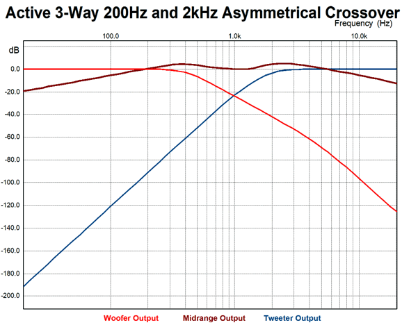
Note how the woofer and tweeter put out less SPL than the midrange; also note that their slopes are far steeper than the midrange. As far as the woofer and tweeter amplifiers are concerned, they see a textbook 3rd-order Butterworth filter The midrange amplifier is not so lucky, as it sees a shallow, lumpy band-pass filter. Here is what the three driver actually put out acoustically:
The sum of the three drivers is frequency flat (at the 0dB line) and phase flat. The midrange's extra hot output is cancelled by the woofer and tweeter outputs and phase shifts, so the summed output from the three drivers falls on the 0dB line. In other words, the fullrange must undo the both woofer and tweeter limitations, which is asking a lot, but less than asking the fullrange to actually cover a full-range of frequencies from 20Hz to 20kHz. After my having looked good and hard that these last two graphs, I am now inclined to raise the crossover frequency between the woofer and the midrange to something close to 500Hz. To be frank, this is where I actually started.
I loved the idea of using a fullrange driver, but worried about it having to reproduce deep bass and extremely high frequencies.
In other words, I wanted to help the fullrange while still retaining as much fullrange goodness as possible, such as seamless midrange and something close to phase flat response. Using three amplifiers per channel might seem excessive, but class-D amplifiers are cheap and powerful, perfect for driving the woofer. A tube-based amplifier, either single-ended or push-pull, would power the fullrange; while the tweeter amplifier could also be tube-based, I would certainly lean towards a single-ended amplifier, even if it was solid-state.
Remember, most tweeters need to be padded with a two-resistor fixed attenuator, as they often produce far more SPL than the average woofer. But when the tweeter gets its own power amplifier, there's no need for any padding of the tweeter at the tweeter's terminals, as we can pad its amplifier's input instead, sidestepping the need to throw away amplifier voltage swing. In other words, the tweeter amplifier becomes effectively far more powerful. For example, if the tweeter normally received -6dB of attenuation through a two-resistor padding network, which delivers 50% of the amplifier output voltage to the tweeter, then the tweeter amplifier has effectively become four times more powerful. Thus, a high SPL tweeter can roar with a 10W power amplifier, as it can match the SPL of the same tweeter that works into the -6dB padding network hooked up to a 40W amplifier. I mentioned this many times before, but it is worth repeating: when you tri-amp, you seldom, if ever, hear the tweeter amplifier clip; the bass amplifier, on the other hand, will clip like crazy. The result is that your ears will assume that you are using a 1,000W power amplifier, as it's the tweeter that most readily betrays clipping and woofer simply lack the high-frequency bandwidth to reproduce the sharply clipped signals.
Music Recommendation: Jane Monheit's Taking a Chance on Love As always, this album is available at Tidal. (No, I do not get a kick-back or discount or anything other than streamed music that I pay for from Tidal.) //JRB
User Guides for GlassWare Software Since I am still getting e-mail asking how to buy these GlassWare software programs:
For those of you who still have old computers running Windows XP (32-bit) or any other Windows 32-bit OS, I have setup the download availability of my old old standards: Tube CAD, SE Amp CAD, and Audio Gadgets. The downloads are at the GlassWare-Yahoo store and the price is only $9.95 for each program. http://glass-ware.stores.yahoo.net/adsoffromgla.html So many have asked that I had to do it. WARNING: THESE THREE PROGRAMS WILL NOT RUN UNDER VISTA 64-Bit or WINDOWS 7 & 8 or any other 64-bit OS. One day, I do plan on remaking all of these programs into 64-bit versions, but it will be a huge ordeal, as programming requires vast chunks of noise-free time, something very rare with children running about. Ideally, I would love to come out with versions that run on iPads and Android-OS tablets.
|
Special Thanks to the Special 86!
I am truly stunned and appreciative of their support. In addition I want to thank the following patrons:
All of your support makes a big difference. I would love to arrive at the point where creating my posts was my top priority of the day, not something that I have to steal time from other obligations to do. The more support I get, the higher up these posts move up in deserving attention. Only those who have produced a technical white paper or written an article on electronics know just how much time and effort is required to produce one of my posts, as novel circuits must be created, SPICE simulations must be run, schematics must be drawn, and thousands of words must be written. If you have been reading my posts, you know that my lifetime goal is reaching post 1,000. I have 532 more to go. My second goal is to gather 1,000 patrons. I have 914 patrons to go.
The Tube CAD Journal's first companion program, TCJ Filter Design lets you design a filter or crossover (passive, OpAmp or tube) without having to check out thick textbooks from the library and without having to breakout the scientific calculator. This program's goal is to provide a quick and easy display not only of the frequency response, but also of the resistor and capacitor values for a passive and active filters and crossovers. TCJ Filter Design is easy to use, but not lightweight, holding over 60 different filter topologies and up to four filter alignments: While the program's main concern is active filters, solid-state and tube, it also does passive filters. In fact, it can be used to calculate passive crossovers for use with speakers by entering 8 ohms as the terminating resistance. Click on the image below to see the full screen capture.
Tube crossovers are a major part of this program; both buffered and un-buffered tube based filters along with mono-polar and bipolar power supply topologies are covered. Available on a CD-ROM and a downloadable version (4 Megabytes). |
||


| www.tubecad.com Copyright © 1999-2019 GlassWare All Rights Reserved |