| John Broskie's Guide to Tube Circuit Analysis & Design |
31 August 2019 Post Number 475
Errata
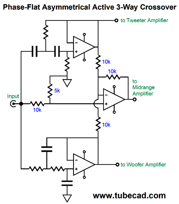
What is different is that the 5k resistor was labeled 10k before. As I made the original schematic, I knew something was off, but I could not spot it. It even troubled my sleep. I sensed that some break in symmetry or balance marred schematic. I found it finally. The 5k resistance was needed to balance the two 10k resistors, which are effectively in parallel, that fed the differential amplifier's inverting input. The wrong value still produced a flat frequency response from the three drivers, but it required more output from the filler driver.
Odd Experience Okay, is -5% really all that much? It depends where you start at; for example, if you start at 100%, losing 5% is not that big a deal, as you are still plenty motivated to keep listening. An analogy might be found in watching TV or Netflix. Below a certain threshold of interest, you move on to something else. With the tube-based headphone amplifier, the added 5% made the album worth hearing; without the 5% boost, I wanted to move on to another album. Never forget that in human affairs, the marginal isn't always marginal. Fourteen years ago in post number 4, I put it nicely:
(Be sure to read the whole post, as it is a good one.) In order to update this to today's standards and inflation, the first two sentence should read: "Charming as these stories no doubt are, how does this justify $20k interconnect cables and magic rocks? First of all, I believe that anyone who sells $20k interconnects should not be allowed to die a natural death..." What I took away from my recent headphone listening sessions was that all the crazy effort and expense of tube gear is more than worth it, as my appreciating and enjoying music that I would otherwise not listen to is hugely valuable and indispensable.
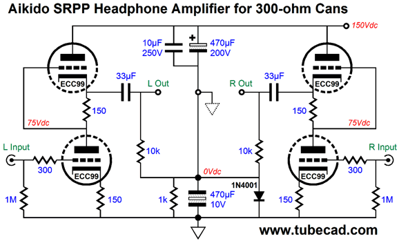
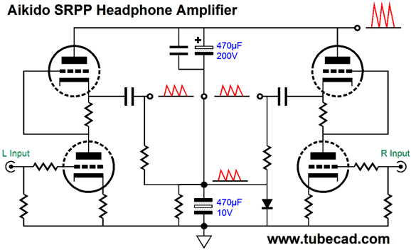
SRPP with Aikido Mojo First, let's get some context. Say you own high-impedance headphones, something between 150 to 600 ohms; and let's say you own high-quality smart phone or fancy portable MP3 player or a standalone DAC with headphone outputs—none of which can deliver enough voltage swing into your relatively high-impedance headphones, as all these signal sources were designed to drive 16- to 32-ohm headphones, which require high current, but low voltage swings. In addition, you long for some tube glow, for a warmer more humane sonic presentation. All your friends and all the online forums shout out SRPP. Okay, that is the context. Now, let's build a high-PSRR SRPP headphone amplifier. Here is an example from post 367.
The power supply's RC filter holds two 470µF capacitors in series; the top is rated for 250V, while the bottom need only be rated for 6.3V to 16V. Because the two capacitors share the same value, they define a two-capacitor AC voltage divider. In other words, half of the B+ voltage ripple will appear at their nexus, which is where we take the headphones' ground. The result is that the headphone drivers can't see the ripple, as it is equal in magnitude and phase. Remember the headphone driver is an intrinsically differential device; if there is no voltage differential across its terminals, there is no diaphragm movement.
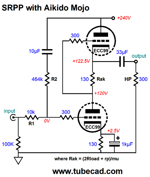
Read the complete explanation in post 367. I can imagine that some will complain that the pseudo ground will dirty the sound due to the electrolytic capacitors. Maybe, maybe not. Perhaps, this arrangement will sidestep the poor capacitor quality just as it sidesteps the B+ voltage ripple and the SRPP's poor PSRR. Okay, let's try something new.
This SRPP drips with Aikido mojo. The two-resistor voltage divider that spans the input to the B+ voltage through the 10µF capacitor leaks just enough power-supply noise into the bottom triode's grid to create a power-supply noise null at the SRPP's output. The SRPP stage inverts the input signal at its output, so the small sampling of power-supply noise becomes inverted and cancels at the output. This circuit will not work if you place a volume potentiometer in front of the 10k input resistor, as the assumption is that the headphone amplifier's input attaches to a low-impedance signal source, say the headphone output of a DAC or portable MP3 player (DAP). By the way, the signal source that was intended to drive low-impedance headphones is now greatly unloaded by the 10k input impedance, so its distortion will drop dramatically and its output stage may never leave its small class-A window of current swings. How do we find resistor R2's value. If the bottom triode cathode resistor is unbypassed then R2 should be roughly mu times bigger than R1; but with the bypassed cathode resistor, we have to find it empirically, alas.
More Phase-Flat Crossover Designs
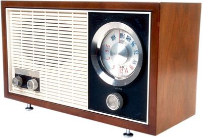
I had to resist the urge to write them off as weirdoes, as cretins, or as philistines, and thinking such uncharitable thoughts as they must also love cheap jug wine, served in Styrofoam cups; had they been indifferent to music, however, dismissing them would have been much easier. (See post 415 under the section titled, Why Tubes, for a related story.) As I pondered the paradox of music lovers who disdained high-quality sound, I asked myself: is there some way in which a 4-inch fullrange in a table radio or old car radio is sonically superior to a three-way high-end loudspeaker that costs over $10,000? Sure there is. It's obvious when we think about it.
Other than the 1st-order crossover, most crossovers designs that offer steeper slopes botch the speaker's phase response. In turn, a botch phase response results in botched transients. Alas, 1st-order crossovers are supremely rare in high-end loudspeakers. Why? The 1st-order crossover make huge demands on the drivers due to its shallow attenuation slope of only -20dB per decade of frequencies. For example, a tweeter crossing over at 5kHz will only be down by -20dB at 500Hz; whereas, a 3rd-order crossover at the same frequency would result in the tweeter being -60dB down at 500Hz, a hundred times less signal compared to the 1st-order crossover. In addition, even if a loudspeaker company knows that its speaker would sound better with 1st-order crossovers, the company hates having to replace burnt tweeters, so higher-order crossovers it is—in spite of the worse sound. In the sharpest contrast, the single speaker in the table radio preserves much more of a flat phase than the $10,000 speaker with a 3-way, 3rd-order crossover. Even if the single speaker's phase departs from flat across the audio bandwidth, it will do so gradually, seamlessly. Beyond flat phase, a new question is, What would these table-radio lovers prefer to hear over wide bandwidth, deep bass and sparkling highs? Perhaps, they deem a limited bandwidth a feature, not a liability. How is that possible? Long ago, about 25 years ago, I built a simple tube-based headphone amplifier to drive my Sennheiser HD580 headphones I owned at the time. I used two output coupling capacitors in parallel, a 30µF Solen polypropylene and 2µF exotic audio-grade capacitor (a TRT InfinityCap or WonderCap, I believe). Well, when I encountered a thick-sounding recording that so obscured the vocals that I could not understand the lyrics, I would listen with only the 2µF coupling capacitors. The deep bass was gone (a 265Hz cutoff frequency with 2µF), but the midrange greatly increased in clarity, usually enough so that I could finally understand what was being sung. Perhaps, these table-radio lovers were able to hear the vocals more clearly on the single fullrange driver, with the midrange reproduction detached from the thundering bass and screechy highs. Perhaps, for them, the music's message was more important than the semantically-void extremes of the audio spectrum. In short, if we can make better crossovers, phase-flat crossovers, table radios will no longer stand a chance against a high-quality three-way loudspeaker. After drawing the schematics for my last post, I wondered about the active asymmetrical three-way crossover, as so much had not been explored. When I ended that post, I had run out of time, not ideas. My design example had used 3rd-order slopes for the woofer and tweeter, while the midrange got lumpy 1st-oder slopes.
My first thought was that I should try 2nd-order slopes instead, as they would prove easier in accommodating the woofer and tweeter own intrinsic mechanical 2nd-order crossovers. (Ignore this portion of my thinking right now, as I return to it later.)
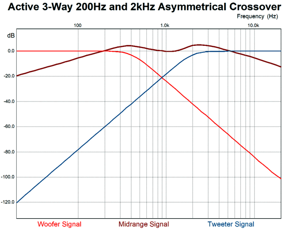
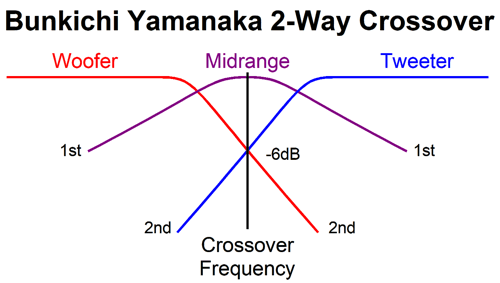
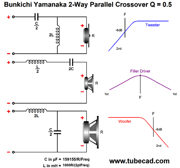
My extreme thought was: what would happen if the woofer and tweeter didn't cross over at 200Hz and 2kHz, but at the same frequency, say 1kHz? What signal would the midrange get, if any? I ran a quick SPICE simulation and I saw the same crossover slopes as I had seen before in the Bang and Olufsen Uniphase loudspeaker line, but with the difference that the woofer and tweeter were down -dB, not -3dB at the crossover frequency. After some research, I discovered that the phase-flat 2nd-order crossover was invented by Bunkichi Yamanaka of Matsushita in 1967 and that the Technics SB-7000 three-way loudspeaker was the first application of the three-driver two-way Yamanaka crossover.
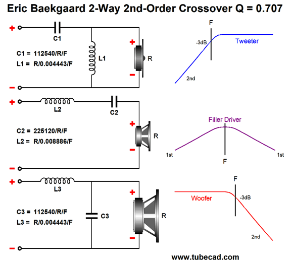
Ten years later, Eric Baekgaard, a Bang and Olufsen employee, wrote a paper in the May 1977 issue of the JAES that showed the new math for the Yamanaka crossover based on a 2nd-order filter Q of 0.707 (same as the Butterworth), not Yamanaka's original Q of 0.5 (the same as the Linkwitz-Riley, predating it?). In addition, Baekgaard created a 3rd-order version of the crossover.
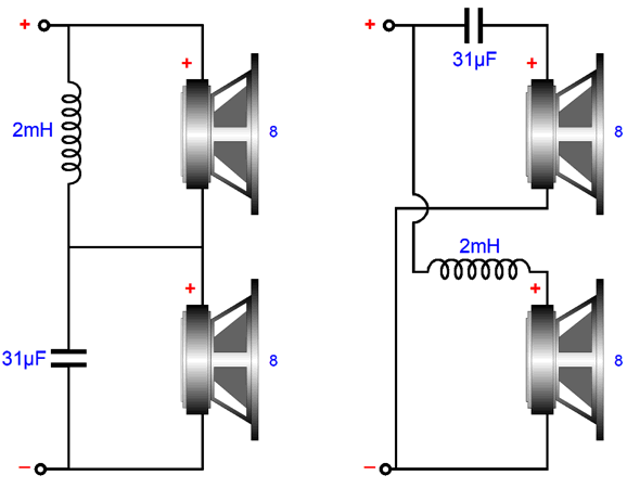
Okay, before I get way ahead of myself, let's start with the basics, beginning with the 1st-order crossover.
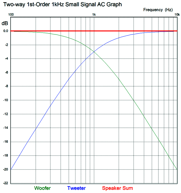
Super simple—even the math. Capacitor = 159155/R/F The woofer and tweeter amplitude and phase plots sum to unity: in other words, both flat frequency and phase response.
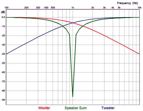
Note that both the woofer and tweeter are down by -3dB at the crossover frequency and that they differ by 90 degrees in phase at that frequency. Now, -3dB implies that the signal is at only 70.7% magnitude at the crossover frequency, which seems to imply a sum of 141.4%, which further implies a boost of 3dB. This would hold true if the two drivers were in perfect phase with each other, but they aren't, as each has shifted by 45 degrees and in opposite directions, making total difference 90 degrees. To find the actual signal voltage we must do some easy math. The Cos(45), whether +45 or -45 degrees, equals 0.707, which against the preexisting attenuation of 0.707, yields 0.5 per driver, which sums to unity, as 0.5 plus 0.5 equals 1. Moreover the two 45-degree phase shifts sum to zero, as -45 + 45 = 0, delivering a flat phase response. Once we move up a 2nd-order crossover, either a Butterworth or Linkwitz-Riley, the phase difference between woofer and tweeter increases to 180 degrees, 90 degrees per driver. The workaround is to flip the phase on the tweeter, which results in a +3dB hump at the crossover frequency with the Butterworth alignment and flat frequency response with the Linkwitz-Riley. Many make a big deal out the inverted connection the tweeter results in both the woofer and tweeter being entirely in phase with each other, ignoring that tone bursts and square wave still come out garbled, due to the phase shift. On the other hand, if we run both the woofer and tweeter with no phase reversals, we get a big suck-out at the crossover frequency.
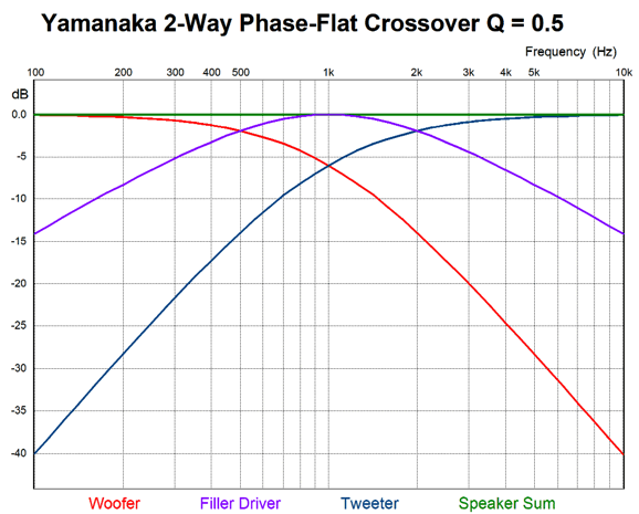
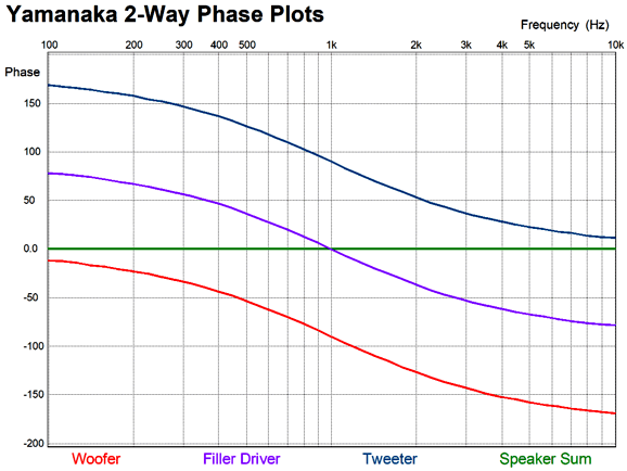
What Bunkichi Yamanaka realized was that we could fill in the gap with a midrange or, as it was later named, a filler driver. This filler driver gets a 1st-order band-pass filter that centers at the crossover frequency. When we sum the acoustic outputs from the three drivers we see flat frequency response and phase response.
As you can easily guess, getting this to work perfectly takes some doing with real speaker drivers, especially as the crossover increases, as the wavelengths shorten significantly. For example, the wavelength of a 5kHz tone is only 2.7 inches or 69mm. On the other hand, if we choose 500Hz as our crossover frequency, the wavelength increases to 27 inches, making the distances between the drivers' centers less of an issue. The second problem we face is that the filler driver must handle a huge bandwidth, due to the shallow 1st-order slopes. Let's stick the 500Hz crossover frequency and we see that the filler driver is only down by -14dB at 50Hz and 5kHz. That is not much.
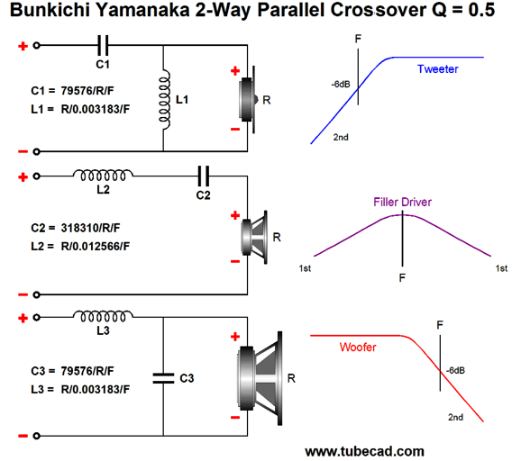
But let's look at the situation differently: assume that you wish to use an existing fullrange driver and run it full bandwidth—all by itself. Now you face the obvious problems of having to reproduce deep bass and avoid intense high-frequency beaming, as asking any driver to cover the full range of audio frequencies is asking a great deal, hence the rarity of fullrange drivers. In contrast, using a 500Hz crossover frequency with the Yamanaka crossover greatly reduces the burden on the fullrange, as its peak output occurs at 500Hz, not 50Hz. In fact, we can look at the woofer and tweeter as being sonic aids for the fullrange filler driver, not as the two primary drivers. Few things are as useful as a change in perspective. The Yamanaka crossover is easy enough to implement. All that is needed is three drivers, three capacitors, and three inductors. Of course, we can add Zobel networks and two-resistor voltage divider attenuators as needed.
The formulas are straightforward and require nothing more than simple four-function hand calculator. On the other hand, the layout of the formulas this way obscures the ratios. So here is the same schematic and underlining math, but with different labeling of the formulas.
Note how two and one half repeat throughout. The woofer and tweeter effectively see a 2nd-order crossover with a Q of 0.5 and both drivers are down -6dB at the crossover frequency. The big difference is that we don't flip the phase on the tweeter, as we normally would two with the Linkwitz-Riley 2nd-order crossover. This is critical, as we want to preserve the phase and create a suck-out at the crossover frequency, which the filler driver fills in. Next, let's look at Eric Baekgaard's reinvention of the Yamanaka crossover.
The difference is found in the 2nd-order crossover Q of 0.707, rather than the Yamanaka's 0.5. The result is that the woofer and tweeter are down only -3dB at the crossover frequency; more importantly, the filler driver is down -17dB at one decade below or above the crossover frequency. For example, with a crossover frequency of 500Hz, the filler driver will be down -17dB at 50Hz and 5kHz, which is -3dB better than with the Yamanaka Q of 0.5. Next, we look at Baekgaard's 3rd-order version.
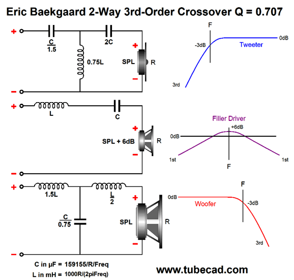
All the drivers must be in the same phase. Once again, the alignment is a Butterworth and the woofer and tweeter are down -3dB at the crossover frequency; the filler driver still sees 1st-order slopes, but it is down a full -20dB at one decade below or above the crossover frequency.
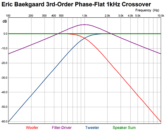
The huge difference is that the filler driver must offer an SPL per Watt that is 6dB greater than the woofer and tweeter. This not that big a hardship, as usually the woofer offers the worst efficiency and the midrange and tweeter must be padded to lower their SPL to match the woofer's. In other words, finding a fullrange that offer 6dB more SPL than the woofer should not prove that difficult. Baekgaard's 3rd-order version also delivers a flat frequency sum and flat phase response.
Note the clean tone burst of three 1kHz cycles and that the filler driver puts out 6dB more ouput, 2Vpk, than the woofer and tweeter, the sum is 1Vpk. Also note how all three drivers are still moving after the burst, yet they sum to silence. In addition, it offers far more protection to the tweeter, as the tweeter is down -60dB at one decade below the crossover frequency. This is huge, as -60dB equals a thousand-fold reduction in signal magnitude. The downside is that as we move up in crossover order, part tolerance becomes critical and the drivers own non-flat impedances becomes a bigger problem in a passive crossover, which helps explain why active crossovers offer so many advantages.
Problems with the Yamanaka and Baekgaard Crossovers
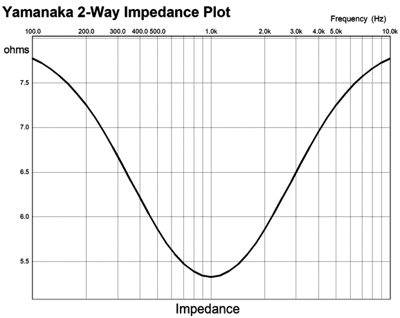
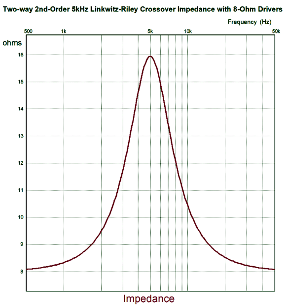
In addition, only voltage-output amplifiers can be used with Yamanaka and Baekgaard crossovers, as the dipping impedance will force a dipping output at the crossover frequency with a current-output amplifier. Even feedback-free tube-based power amplifiers prompt a dip due to their high output impedance. For example, a single-ended, feedback-free power amplifier with an output impedance of 2 ohms will create a -3.5dB broad dip centered at the crossover frequency. This situation is just the opposite of the Linkwitz-Riley crossover, which creates an impedance peak equal to twice the nominal loudspeaker impedance. The doubling of impedance at the crossover frequency will create a peak in the frequency response with a current-output amplifier.
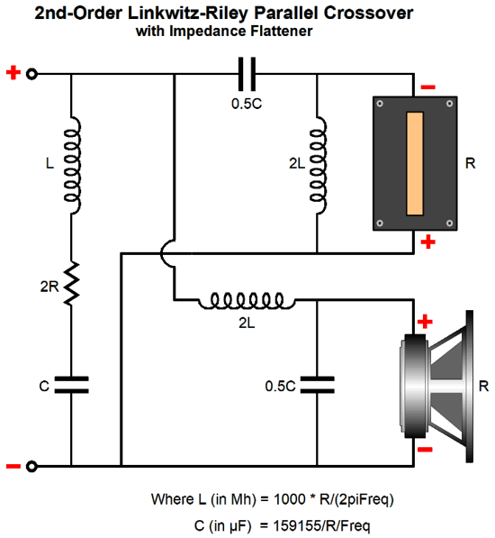
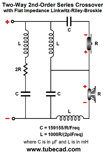
Fortunately, I have solution, which I have shown here before in post 403.
By adding a capacitor and inductor and a resistor twice the value of the loudspeaker nominal impedance, we get a flat impedance plot, making the Linkwitz-Riley-Broskie crossover safe for current-output and tube-based amplifier with high output impedances. I prefer the series arrangement, as the woofer's own series inductance, Le, can be put to use as part of the crossover.
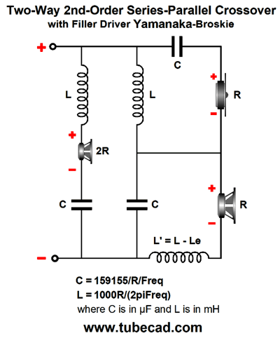
Note the added resistor does not create any sound. In fact, it will be dead silent, but warm. Well, what if we replace the load resistor with a loudspeaker driver?
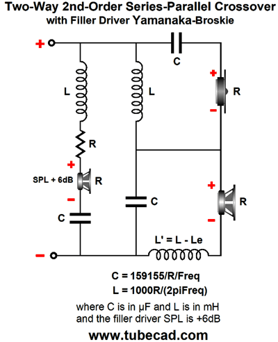
Note that all three drivers are in phase; in other words, do not flip the tweeter phase at its terminals. The added driver's impedance must be twice the woofer and tweeter's impedance. Although 16-ohm speaker drivers are made, this will prove to be a minor hassle. On the other hand, with 4-ohm woofers and tweeters, finding an 8-ohm filler driver is a breeze. One possible workaround with 8-ohm woofers and tweeters would be to place an 8-ohm power resistor in series with an 8-ohm filler driver. The catch is that the filler driver must be 6dB more efficient than the woofer and tweeter.
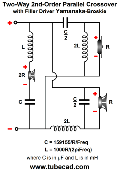
By the way, if the Linkwitz-Riley portion of the crossover looks unfamiliar, it's only due to it being arranged in the series configuration. Here is the parallel configuration, which requires a Zobel network across the woofer to null its inductance.
Once again, b e sure to note that in last schematics that the tweeter phase was not flipped. This is important, as the crossover are now variations on the Yamanaka crossover. In other words, the last three schematics show phase flat crossovers, with the added bonus of being impedance flat as well. What about the Baekgaard 3rd-order crossover? Can I make it impedance flat? No, I cannot. Well, at least not now. The problem is the only way raise a drooping impedance is to place series peaking impedance, which will prompt an attenuation at the crossover frequency. On the other hand, if use active crossover filters and three separate power amplifiers, then no drooping impedance can result.
Active Yamanaka Crossovers
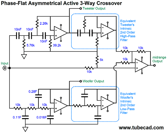
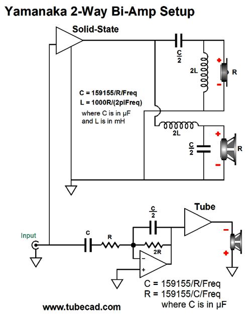
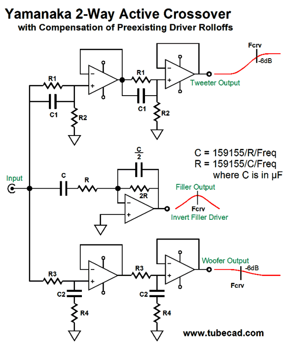
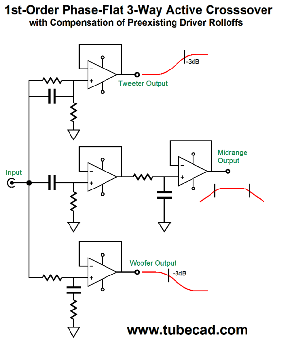
In other words, two stereo power amplifiers of differing technology could be used. Does it still seem too crazy? I don't think so, as my guess is that the fullrange filler driver will define the loudspeaker's sonic signature. In addition, by so greatly limiting the low-frequency demands on the tube power amplifier, a much smaller output transformer could be used with hefty output tubes. Reproducing low frequencies requires big output transformers. As I have pointed out many times before, ideally the output transformer should be at least twice as big as the power transformer; it never is, but it should be, as we expect the output transformer to extend down below the relatively high wall-voltage frequency of either 50Hz or 60Hz. If we are willing to go the tri-amp route, then making an active version of the Yamanaka crossover is not difficult. The filler driver must have its phase flipped at its connection to its power amplifier, as its active filter inverts the signal phase, while the woofer and tweeter filters don't. (By the way, if the filler amplifier offers +6dB more signal gain than the woofer and tweeter amplifiers, we can do not have to use C/2 and 2R, as C and R will work just as well.) Alternatively, we can use the following variation, which I prefer.
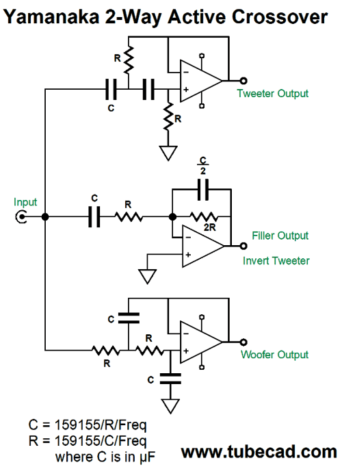
Why do I prefer it? Two fewer capacitors is a good start, especially if you are inclined to buy exotic $100 capacitors. The 5k and 10k resistors should be tightly matched, say 0.1% resistors. Second, and far more importantly, this version allows us to move away from the Yamanaka crossover if we choose. For example, rather than have the single crossover frequency of 1kHz, we could give the filler/midrange more bandwidth, say 500Hz to 2kHz, making a phase-flat three-way loudspeaker system. This option was not available with the previous version. Since I am a born hacker, I can never have enough options. In contrast, as I am reminded at each RMAF I attend, most hate options— just detest them. Why? A good guess would be fear and insecurity. What if I chose wrongly? Won't the world end? Won't I be subject to public ridicule? Besides, you, John Broskie, are the expert, so act your part and tell me what to do. Am I wrong or are many audiophiles amongst the most pusillanimous of hobbyists? Or is it more along the lines that many believe that there is only one perfect solution, approach, setup, circuit, part value...? Options contradict the one perfect. Okay, back to the topic at hand, one possible exception might be the following.
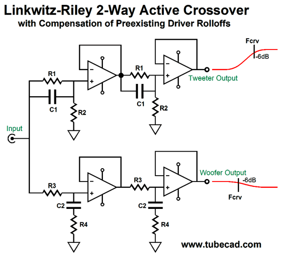
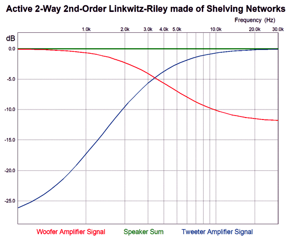
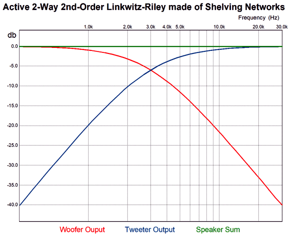
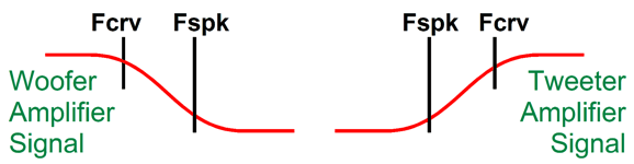
This is a Linkwitz-Riley active crossover that acknowledges that the tweeter comes with its own high-pass 2nd-order filter at its resonant frequency and that the woofer comes with its own low-pass 2nd-order filter at some high-frequency beyond the diaphragm's ability to function as piston. In other words, this crossover only provides the missing portions of the woofer and tweeter slopes. For example, say the tweeter's resonant frequency is 600Hz and the woofer droops off at 6kHz and the crossover frequency is 3kHz. Here are the signals that the woofer and tweeter amplifiers will see.
Looking at the graph above, would you have guessed that the crossover frequency was 3kHz? Note that the woofer's slope only extends up to 6kHz and the tweeter's down to 600Hz. Beyond these frequencies, the drivers own intrinsic roll offs take over. Here is what the woofer and tweeter sonically put out.
This what we want: a true Linkwitz-Riley crossover with a Q of 0.5 that sums to a flat frequency response. The next step is to add a 1st-order band-pass filter for the filler driver and to not invert the tweeter's phase and we end up with a Yamanaka phase-flat crossover.
Six capacitor and ten resistors are needed. The math get a tad more difficult than before, but really not that big a deal. First, we need to set the attenuation ratio with the two-resistor voltage divider created by R1 & R2 and R3 & R4. Or rather, we make the ratio between the resistors match the ratio between the crossover and the speaker driver's effective, implicit, internal, intrinsic 2nd-order filter. With the tweeter, this filter arises at the tweeter's resonant frequency; with the woofer, at the woofer's high-frequency rolloff frequency. Let's label the crossover frequency, Fcrv, and the frequency of the driver's intrinsic 2nd-order filter, Fspk.
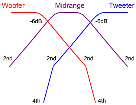
Beginning with low-pass section (the woofer's crossover), choose R1's value. Now, we find R2's value. By the way, the assumption is Fspk is greater than Fcrv. R2 = R1/(Fspk/Fcrv – 1) Next, we find C1's value. C1 = 159155/Fcrv/(R1 + R2) We move on to the high-pass filter for the tweeter. This time, the assumption is Fcrv is greater than Fspk. R3 = R4/(Fcrv/Fspk – 1) C2 = 159155/Fcrv/(R3||R4) Where || means in parallel with, which we can rewrite as X||Y = XY/(X + Y) Bear in mind that these cascading shelving networks do not provide protection that a true 2nd-order filter would. In other words, we need to ensure that the crossover is sufficiently high enough to protect the tweeter. For example, if the tweeter's resonant frequency is 1kHz, then a 2kHz crossover frequency is a bad idea. On the other hand, a crossover frequency of 5kHz might work. A sneaky alternative approach, with a three-way loudspeaker system, we can place the woofer-midrange crossover frequency at the tweeter's resonant frequency and the midrange-tweeter crossover frequency at the woofer's high-frequency roll-off frequency.
This would allow us to use a true 2nd-order filters throughout and two driver's intrinsic 2nd-order filters take the place of the missing 2nd-order low-pass and high-pass filters. Mind you, we are back to a non-phase-flat loudspeaker, as the 2nd-order crossovers used throughout to not add up to phase flat, only frequency flat. If we want phase-flat as well, the 1st order crossover that includes the woofer and tweeter intrinsic 2nd-order filters will do the job, but the tweeter must be amazingly robust or the power amplifier that feeds it must be especially weak.
If 600Hz and 6kHz crossover frequencies are used, it just might work without damaging the tweeter.
This post took a ton of effort and time to put together. If you just discovered my website, welcome aboard. If you are a long-time reader, then help me make more posts like it. Benjamin Franklin famously said that "time is money"—and he was painfully right, as was the first to say it, Antiphon, a fifth-century Athenian orator. And Logan Pearsall Smith not so famously said, "My life is a bubble; but how much solid cash it costs to keep afloat that Bubble!" Keeping the bubble known as the Tube CAD Journal afloat takes a huge amount of time, so help keep it afloat.
Music Recommendation: Aaron Neville's Warm Your Heart
//JRB
User Guides for GlassWare Software
For those of you who still have old computers running Windows XP (32-bit) or any other Windows 32-bit OS, I have setup the download availability of my old old standards: Tube CAD, SE Amp CAD, and Audio Gadgets. The downloads are at the GlassWare-Yahoo store and the price is only $9.95 for each program. http://glass-ware.stores.yahoo.net/adsoffromgla.html So many have asked that I had to do it. WARNING: THESE THREE PROGRAMS WILL NOT RUN UNDER VISTA 64-Bit or WINDOWS 7 & 8 or any other 64-bit OS. I do plan on remaking all of these programs into 64-bit versions, but it will be a huge ordeal, as programming requires vast chunks of noise-free time, something very rare with children running about. Ideally, I would love to come out with versions that run on iPads and Android-OS tablets.
|
John Gives
Special Thanks to the Special 84
I am truly stunned and appreciative of their support. In addition I want to thank the following patrons:
All of your support makes a big difference. I would love to arrive at the point where creating my posts was my top priority of the day, not something that I have to steal time from other obligations to do. The more support I get, the higher up these posts move up in deserving attention.
If you have been reading my posts, you know that my lifetime goal is reaching post number one thousand. I have 525 more to go. My second goal is to gather 1,000 patrons. I have 916 patrons to go. Help me get there.
Support the Tube CAD Journal & get an extremely powerful push-pull tube-amplifier simulator for TCJ Push-Pull Calculator
TCJ PPC Version 2 Improvements Rebuilt simulation engine *User definable
Download or CD ROM For more information, please visit our Web site : To purchase, please visit our Yahoo Store: |
|||


| www.tubecad.com Copyright © 1999-2019 GlassWare All Rights Reserved |