| John Broskie's Guide to Tube Circuit Analysis & Design |
11 December 2019 Post Number 486
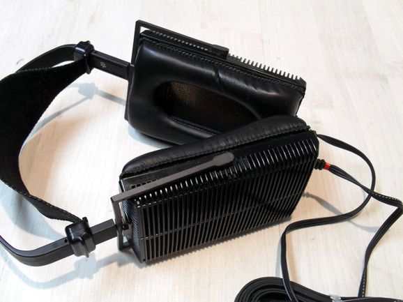
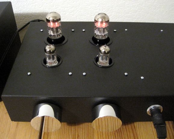
Electrostatic Headphone Amplifier Update I left the quieter JJ 6SN7s in place and tried different 12AX7 tubes. I tried several modern-production 12AX7s and a few NOS gold-standard 12AX7s, both American and European. No clear winner. I thought I could super subtle differences, but I didn't hear any clearly better sounding 12AX7. Indeed, if I left the same tubes in place and just listened to the same track repeatedly, each new listening surfaced new sonic details that I had missed prior. What is going on here? My guess is that the ES HPA-1 doesn't really drive anything, as the capacitive load only becomes a burden at ultra-high-frequencies, but most music holds little high-frequency content and at low amplitude. In short, tube rolling does not seem to be as important as does in other tube-based gear, such as phono stages and dynamic headphone amplifiers. When I listen to my dynamic headphones, if I use the Tilt Control at all, it is usually only once when I change headphones. In contrast, with my Stax headphones, I give the Tilt Control a workout, not only rotating the knob with a change of albums, but with different tracks. Is this a bug or feature? It depends. If you seek pleasant background music, then you would be far better off with languid dynamic headphones. On the other hand, if you seek to peer deeply into the recording, then Tilt Control and super resolution headphones are an essential pairing. My shipment of black hole trims arrived and the electrostatic headphone amplifier looks much better.
I was asked if the optional output coupling capacitors couldn't be used with the electrostatic headphones, resulting in AC coupling rather than employing DC coupling. You certainly could, as the stators are pretty much indifferent to the capacitors, as a 0.1µF coupling capacitor is vastly larger than the headphone capacitance (about 270pF). Just terminate the following 1M grid resistors to ground. Indeed, I would try using 0.01µF capacitors, which would impose a high-pass filter at 16Hz. If the possibility of high DC voltage being that close to head bothers or worries you, then the coupling capacitors are a good workaround. Bear in mind, if a capacitor is going to sing, it is going to do so in this position, due to the several hundred-volt swings. (Singing capacitors are like mini electrostatic loudspeakers. I have heard expensive film and foil capacitors singing away, so spending more won't necessarily help; only actual experimentation will.) My last observation is that the Stax Lambda Pro headphones are disconcertingly uncomfortable. This is surprising as they are so lightweight. Its ear pads, however, are not supple enough and not porous, so your ears sweat. I am searching for replacement ear pads. Just listening to any headphones for a prolonged period is tough, but introduce some physical discomfort and the task becomes unbearable.
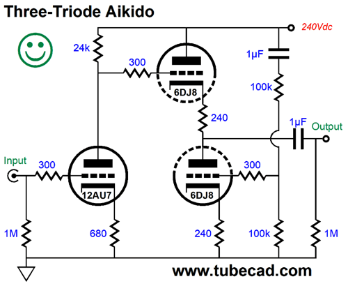
Two-Triode Aikido
The input triode works into a plain plate resistor, not an active load made out of another triode and its cathode resistor. The downside to this three-triode Aikido circuit is that we can no longer do wild tube rolling.
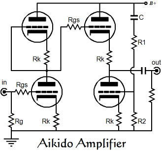
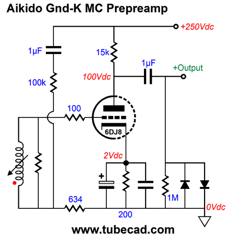
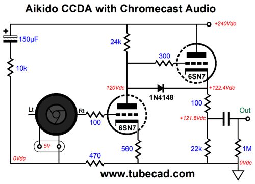
In contrast, the four-triode Aikido allows a wide range of potential tube swapping. For example, an Aikido set up for the 12AU7 can accept a 12AT7, 12BH7, 5963, 5965, and ECC99 in its stead—without having to change any resistor values. (I have held Aikido tube rolling get-togethers, wherein each brought his pair of 6.3V dual triodes. We listened to 6AQ8, 6BQ7, 6BS8, 6CG7, 6DJ8, 6N1P, 6922 tubes, with a surprise contender, the 6BS8, sounding truly fine. (The European 6AQ8/ECC85 also proved impressive.) Stepping down to using just two triodes is possible. I showed how it was so with phono cartridges in post 327 and the Chromecast Audio puck in post 388.
And with the Chromecast Audio puck:
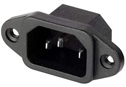
Both of these signal sources offer the advantage of being free-floating. In other words, they don’t attach to a three-prong power cord. If no house ground wall sockets existed, then all signal sources, such as CD players, DACs, FM tuners, tape machines, streaming devices… would also be free-floating. Connections to the house ground break the floating. Today, the IEC 320 C14 power socket is common on high-end audio gear.
One workaround is to use a 1:1 input transformer, as that would break any connections to the house ground, sidestep most ground-loop problems, and would allow easy phase flipping.
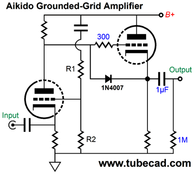
If we can accept the low input impedance, the Aikido grounded-grid amplifier circuit is a contender.
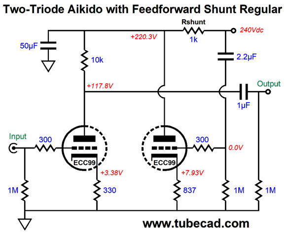
Is there no way we can achieve the goals of low distortion, high PSRR, low output impedance and high input impedance with just two triodes and with a world filled with house-grounded equipment? If we give up on a low output impedance, then the following circuit uses two triodes per channel and offers an excellent PSRR.
The input stage is simply a grounded-cathode amplifier, with nothing fancy. The fancy part is that the second triode is used a feed-forward shunting power-supply noise filter.
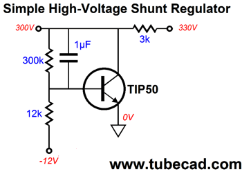
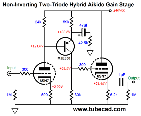
The usual shunting regulator works in a basic negative feedback fashion: something electrically untoward and unfortunate occurs on the B+ voltage; the shunt-regulator's active device sees the perturbation and alters its current flow to counter the problem. In the example shown above, the NPN transistor sees the perturbation through the 1µF capacitor at its base, which prompts the transistor to counter the perturbation by varying its current flow in response. Much like a police detective being called in to solve a murder, the negative-feedback shunt regulator responds to a violation, i.e. a perturbation in the B+ voltage. In contrast, the feed-forward shunting regulator responds simultaneously with the offence. It is proactive, not reactive. Imagine if the police knew in advance when and where a murder was going to happen; they would show up beforehand and prevent it from happening. In this design example, the ECC99 triode's cathode resistor was carefully chosen to match the 1k series resistor at the B+ voltage, as the cathode resistor's resistance added to the inverse of the ECC99's transconductance must equal the 1k resistor's resistance. The 50µF decoupling capacitor is just frosting on the substantial cake, as it takes over where the high-frequency phase-shifts due to internal triode capacitances undermine the feed-forward feedback. Note that we can use a bypass capacitor on the grounded-cathode amplifier's cathode resistor without having to alter the feed-forward shunt circuit. Well, I have come up with another two-triode Aikido circuit, but it is hybrid circuit.
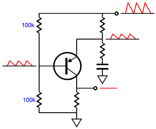
The PNP transistor performs two functions: it inverts the signal leaving the input stage, returning the phase to non-inverting; and it strips away the power-supply noise, not only from the grounded-cathode amplifier input stage but also from the cathode-follower output stage. Let's look at how it inverts.
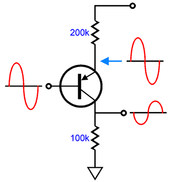
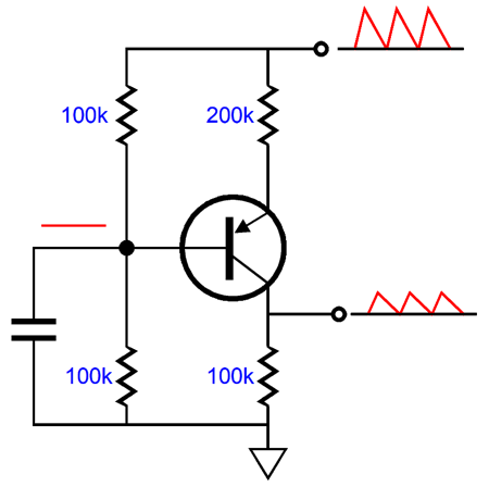
If the collector and emitter resistor were of the same value, then the topology would be that of a PNP-based split-load phase splitter. However, as they do not, we have a common-emitter amplifier with an unusually large emitter resistor. So large, in fact, that we lose gain, about half. Okay, what happens when this circuit encounters power-supply noise?
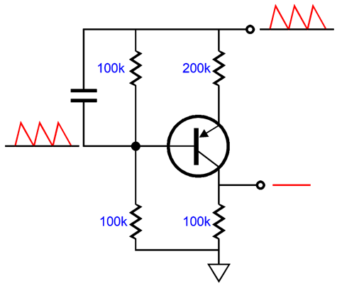
The transistor's base sees none of the noise, due to the shunting capacitor to ground. In contrast, the emitter resistor sees 100% of the power-supply noise at its top, and virtually no noise at its bottom. The varying current flow through the resistor due to the noise is then relayed to the collector resistor. Since the collector resistor is half the emitter resistor value, the noise that appears at the collector is also halved and in phase. Now, what happens if we place the shunting capacitor across the top resistor in the two-resistor voltage divider?
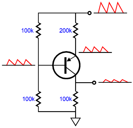
Now, the both the transistor's base and emitter see 100% of the power-supply noise and the emitter resistor sees a fixed DC voltage, which results in a constant-current flow through the collector resistor. Hence, no power-supply noise at the collector. Okay, what happens when we remove the shunting capacitor?
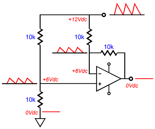
The emitter resistor effectively sees 50% of the power-supply noise, so the emitter resistor sees the power-supply-noise induced current variation that it did in the first example. And as the collector resistor is half the value of the emitter resistor, the collector sees 25% of the power-supply noise at the B+ connection. The last possible configuration is where the transistor's base and emitter both see 50% of the power-supply noise. Before showing this arrangement, think back to an OpAmp-based differential amplifier.
The differential amplifier rejects what is common and amplifies differences. In the example shown above, both the +12Vdc power-supply voltage and its ripple are the common signals and both are rejected at the output. Okay, now lets return to the PNP examples.
The two-resistor voltage divider on the left halves both the DC and AC voltages, while the two-resistor voltage divider on the right only halves the AC voltage. As the emitter resistor sees an effectively fixed DC voltage, but none of the ripple, the current flows steadily through the collector resistor and no power-supply noise leaks into the output at the collector. Okay, let's now replace the two-resistor voltage divider on the left with a grounded-cathode amplifier, which is effectively a two-resistance voltage divider.
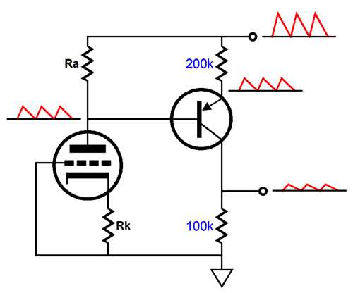
Both the B+ voltage and the power-supply noise are halved by the grounded-cathode amplifier. The impedance presented at the triode's plate is found with the following formula. Zp = rp + (mu + 1)Rk Where rp is the plate resistance and Rk is the cathode resistor value and mu the triode's amplification factor. If we desire a 50% ratio, we start with this formula: Ra = rp + (mu + 1)Rk Where Ra is the plate resistor value. Next we solve for Rk. Rk = (Ra –rp) / (mu + 1) This circuit's output impedance is equal to the collector resistor value. One of our three goals was a low output impedance, so we add cathode follower to the circuit.
Yes, we have a low output impedance, but 25% of the ripple leaks out the output, making a PSRR figure of -12dB. The next step is to greatly enhance the PSRR.
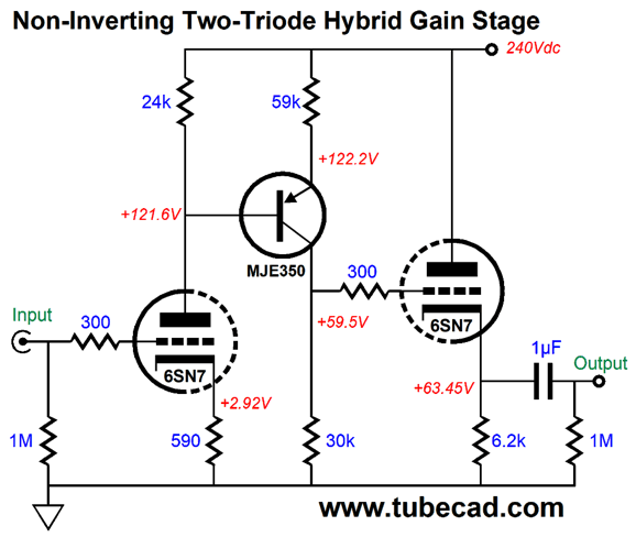
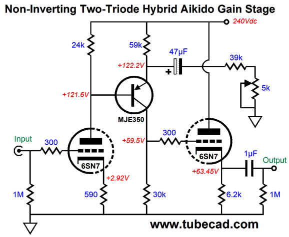
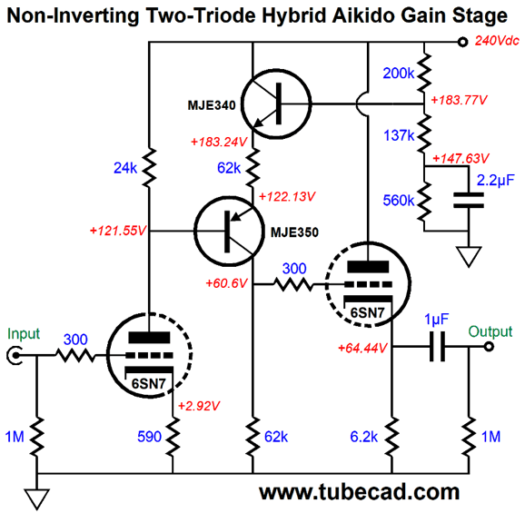
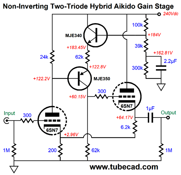
This two-triode Aikido gain stage does not invert the phase and its offer an excellent distortion and PSRR figure along with a low output impedance, thus meeting our three goals. The only problem is finding the optimal value for resistor R2. In SPICE simulations, the above values worked out well. Perhaps you have discerned my distaste for potentiometers. It's true, in general, I hate pots. The exceptions are when no DC current flows through the potentiometer's scraper from the conductive film. Well, we could get away with replacing the 42.5k resistor with a 39k resistor in series with a 5k potentiometer.
Now for the distortion graph.
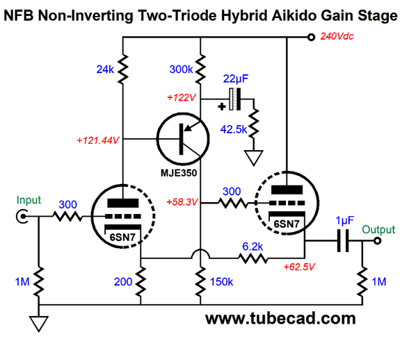
Not bad at all, as the THD comes in at below 0.01%. Some will balk at the 47µF electrolytic capacitor. Unfortunately, a large capacitor value is needed to ensure that the power-supply-noise null goes low enough. One workaround is to add an NPN transistor.
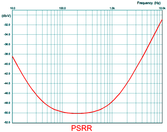
Now, we can get away with 2.2µF film capacitor. Here is the PSRR versus frequency graph for the circuit shown above.
The place to look is where we encounter twice the wall-voltage frequency, 120Hz in the USA and 100Hz in Europe. But what about the high frequencies? Well we do not need to worry about them, as we can add an RC filter to the B+ consisting of a 100-ohm resistor and a 50µF capacitor, either film or electrolytic.
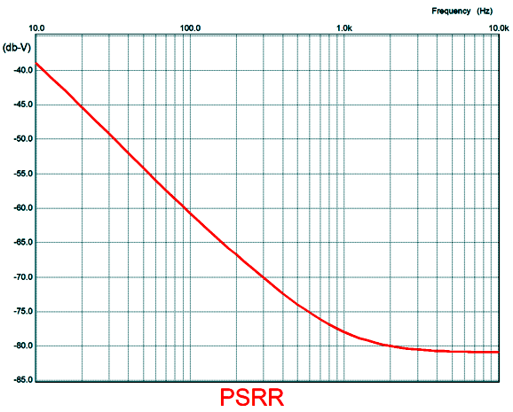
If you are wondering what it would look like with the fancy Aikido mojo and only relying on the RC filter, the answer is that the PSRR would be 40dB worse at 100Hz. By the way, since this circuit does not invert the phase at its output, we can apply a conventional negative feedback loop.
The same arrangement is possible with single transistor version.
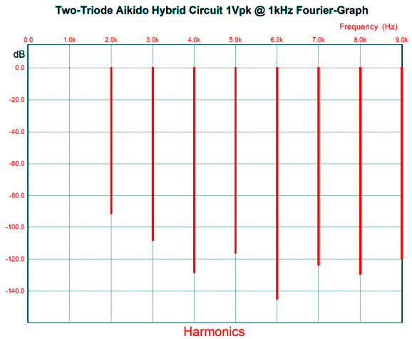
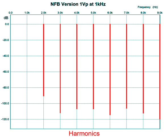
Here is the SPICE-generated Fourier graph for 1Vpk at 1kHz.
The suppressed 3rd and 9th harmonics are great, but I wish the same held true for the 5th and 7th harmonics. What if we did want an inverted output phase? Why would we want such a thing? The old rule in electrical engineering is: Whenever possible invert. Why? With an inverted output we sidestep the problem of the output signal leaking back into the input and create insane positive feedback. The higher the gain, the more dangerous and likely this result becomes. We would still use a PNP transistor, but we apply the tube's signal to its emitter, rather than its base.
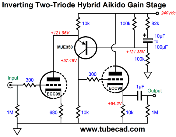
The plate-load resistor and emitter resistor are one in the same. If the triode draws more current, the transistor must draw less and vice versa. Thus, if the triode's grid sees a positive pulse, the triode will draw more current, while the transistor draws less, which results in drop the voltage across its collector resistor, thereby creating a negative pulse. In other words, the positive pulse inverted, which the cathode follower will pass on to the external load. Now, how do we add some Aikido mojo, so we can enhance the PSRR? Well, much like the earlier circuits, we add a capacitor-terminated resistor, but this time it terminates into the B+ connection, not ground.
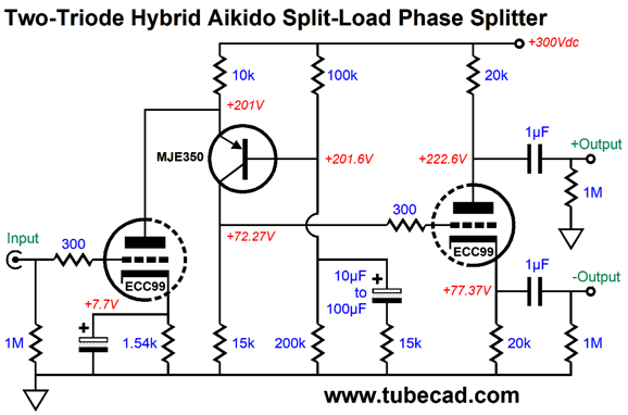
The 82k resistor is effectively in parallel with the 100k resistor, so the AC voltage division favors the ripple. On the other hand, if we wanted to make a phase splitter, we would need to inject 50% of the ripple in each phase's output.
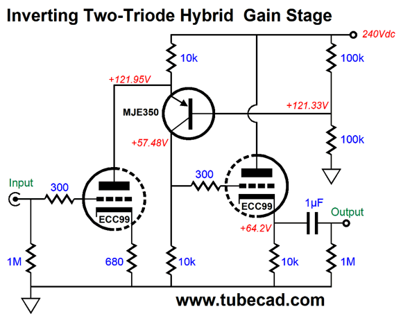
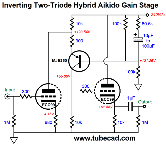
Note how the added resistor and capacitor now terminate into ground and how the input stage's cathode resistor is bypassed to increase the gain. Okay, returning to the gain stage version, I would use the following circuit.
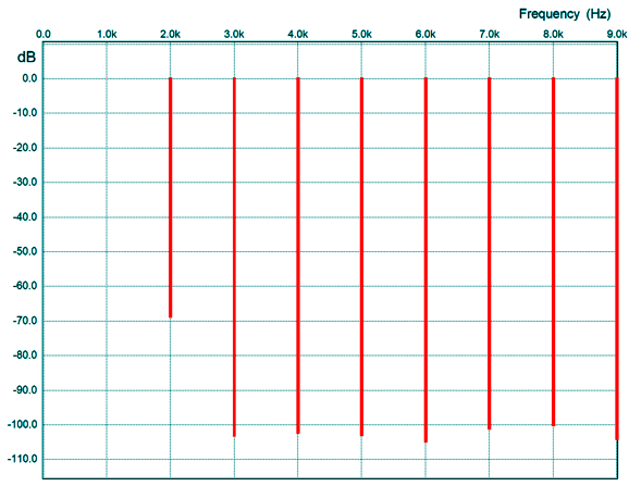
See the difference? I added a 300-ohm emitter resistor, which will linearize the circuit and burn off some gain. Also note that the 82k resistor has been replaced by an 80.6k resistor. The gain come in at 10 (+20dB) and the distortion is 0.037% (mostly 2nd harmonic) in SPICE simulations.
I love seeing the depressed 3rd harmonic. Okay having gone down this more frugal path, we should ask ourselves how do these two-triode Aikido circuits compare to the standard four-triode Aikido?
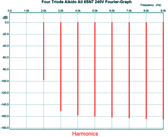
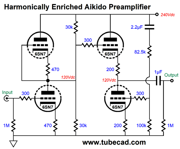
With the same 1Vpk at 1kHz output, the four 6SN7 triodes deliver far lower distortion, but a slightly higher output impedance. Note that other than a wee bit of 2nd harmonics, there's not much distortion here. Well, some complain that it's too clean, preferring a riper and more traditionally fat tube sound. You want harmonically enriched, I will give you harmonically enriched.
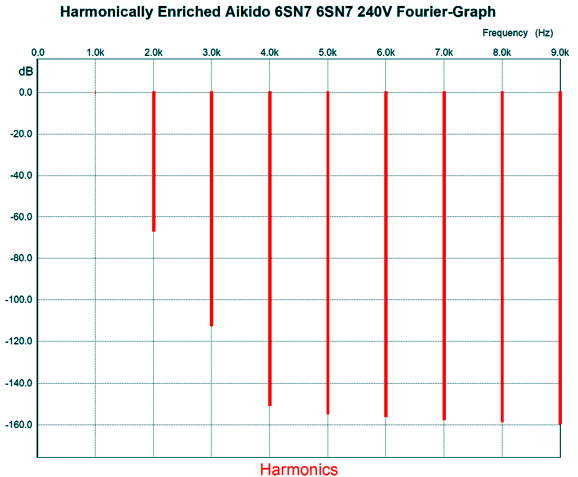
The extra two 30k resistors burn off gain and add more distortion.
No doubt for many this will be the preferred harmonic structure. Remember the whole point of high-end audio is not truth nor any other absolute other than pleasure. As Friedrich Nietzsche so nicely put it: "How little is required for pleasure! The sound of a bagpipe—without music, life would be an error."
Music Recommendation:
Yusuf / Cat Stevens Well, while searching for his albums that came out before Tea for the Tillerman at Tidal, I saw his latest, The Laughing Apple. Dang, it's the old Cat, but older, no longer able to sing those previous high notes. Still, you instantly know his voice and his style of singing and the accompanying guitar play. Apparently, this album did well and, in 2018, was nominated for a Grammy Award for Best Folk Album. It didn't win, but it is certainly well worth hearing. By the way Tidal offer an MQA version.
The next recent album of his that I listened to was Tell "Em I'm Gone!, which is a bluesy album. But it is not just another blues album, as he imparts a greater significance, an almost spiritual overlay, that makes the album stand out. For example, I was sure that I never wanted to hear the song, You Are My Sunshine, ever again. Yet, his cover compelled my attention and admiration. If nothing else, this album sounds great, although not available as an MQA recording at Tidal.
//JRB
User Guides for GlassWare Software
For those of you who still have old computers running Windows XP (32-bit) or any other Windows 32-bit OS, I have setup the download availability of my old old standards: Tube CAD, SE Amp CAD, and Audio Gadgets. The downloads are at the GlassWare-Yahoo store and the price is only $9.95 for each program. http://glass-ware.stores.yahoo.net/adsoffromgla.html So many have asked that I had to do it. WARNING: THESE THREE PROGRAMS WILL NOT RUN UNDER VISTA 64-Bit or WINDOWS 7 & 8 or any other 64-bit OS. I do plan on remaking all of these programs into 64-bit versions, but it will be a huge ordeal, as programming requires vast chunks of noise-free time, something very rare with children running about. Ideally, I would love to come out with versions that run on iPads and Android-OS tablets.
|
I know that some readers wish to avoid Patreon, so here is a PayPal button instead. Thanks. John Broskie
John Gives
Special Thanks to the Special 84
I am truly stunned and appreciative of their support. In addition I want to thank the following patrons:
All of your support makes a big difference. I would love to arrive at the point where creating my posts was my top priority of the day, not something that I have to steal time from other obligations to do. The more support I get, the higher up these posts move up in deserving attention.
If you have been reading my posts, you know that my lifetime goal is reaching post number one thousand. I have 514 more to go. My second goal is to gather 1,000 patrons. I have 916 patrons to go. Help me get there.
Only $9.95
The Tube CAD Journal's first companion program, TCJ Filter Design lets you design a filter or crossover (passive, OpAmp or tube) without having to check out thick textbooks from the library and without having to breakout the scientific calculator. This program's goal is to provide a quick and easy display not only of the frequency response, but also of the resistor and capacitor values for a passive and active filters and crossovers. TCJ Filter Design is easy to use, but not lightweight, holding over 60 different filter topologies and up to four filter alignments: While the program's main concern is active filters, solid-state and tube, it also does passive filters. In fact, it can be used to calculate passive crossovers for use with speakers by entering 8 ohms as the terminating resistance. Click on the image below to see the full screen capture.
Tube crossovers are a major part of this program; both buffered and un-buffered tube based filters along with mono-polar and bipolar power supply topologies are covered. Available on a CD-ROM and a downloadable version (4 Megabytes). Download or CD ROM
|
|||


| www.tubecad.com Copyright © 1999-2019 GlassWare All Rights Reserved |