| John Broskie's Guide to Tube Circuit Analysis & Design |
23 December 2019 Post Number 487
Merry Christmas!
Today, if I still owned the artificial tree, I would hot-glue LEDs of varying colors into the tube sockets, so the their light would shine up into the tubes. In fact, I own a battery-powered string of LED lights that holds 100 while LEDs. I could probably get away with using a white rubber band on each tube and LED, so no heavy ceramic socket would be needed.
Single-Ended Electrostatic Headphone Amplifiers
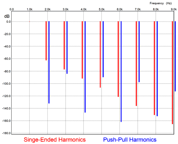
We will leave this arrangement in place. What I am proposing, instead, is that the method by which we obtain the two anti-phase voltage swings be produced in a single-ended fashion, rather than a push-pull one. Why? I would enjoy comparing sonic signatures due to the different harmonic structure that results from single-ended amplification compared to the typical push-pull amplification. In other words, we all know what electrostatic headphones sound like when driven by push-pull amplifiers, but what would the single-ended amplifier's greater even-order harmonics sound like? Could a single-ended output stage warm the typical chilly electrostatic sound?
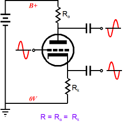
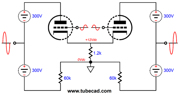
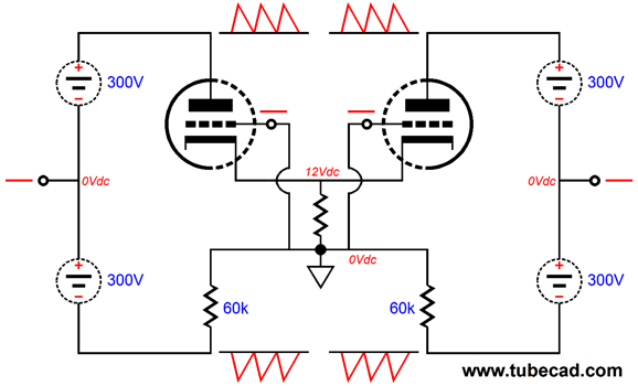
Okay, the first question must be: is a balanced set of output voltage swings possible with a single-ended output stage, an output stage that uses only one output device? Sure it is. Think of the split-load phase splitter, which holds one triode and yet delivers two anti-phase output signals.
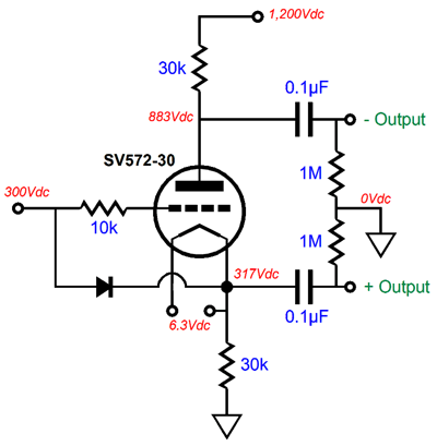
Holding just one triode, this circuit is about as single-ended as you can get. In fact, we could use a split-load phase splitter to drive electrostatic headphones, if we are willing to pay the price. Price, what price? For example, a push-pull output stage that held two output triodes might need a power-supply voltage differential of 600V (+/-300V) and an idle current flow of 5mA per triode. In contrast, the single-ended output stage with one output triode that would deliver similar performance requires a power-supply voltage differential of 1200V and an idle current flow of 10mA for the single triode. In other words, the solitary triode in the single-ended arrangement must see twice the voltage drop and twice the idle current flow of a single triode in a push-pull arrangement, making for four times the plate dissipation. With a cathode-to-plate voltage differential of 600V and an idle current flow of 10mA, the plate will dissipate 6W at idle. In other words, we will need a high-voltage power triode, such as the 811 or the SV811-10 or the SV572-30—and maybe the 6HV5, which is a beam triode (not a tetrode) in a compactron envelope with no anode cap.
In addition, the output tube's heater element must get its own floating power supply and this supply must attach to the cathode, as the cathode will undergo huge—truly huge—voltage swings. In short, finding a suitable output tube isn't as easy as might seem at first. The big problem is the required high-voltage maximum plate voltage rating. In addition, the power triode should exhibit a high mu. The more I think about it, the SV572-30 might be the best choice.
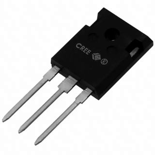
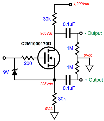
The SV572-30, however, is not cheap and its heater element draws 4A. In contrast, they are making some amazingly high-voltage MOSFETs these days, particularly the SiC types, such as the C2M1000170D, a 1700V and 69W and 200pF input capacitance silicon-carbide power MOSFET that cost about $5.
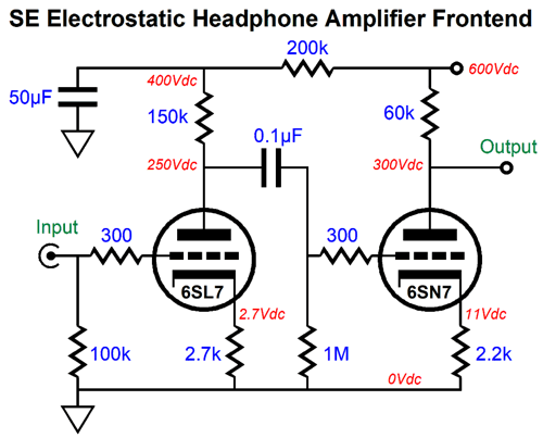
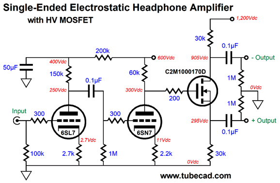
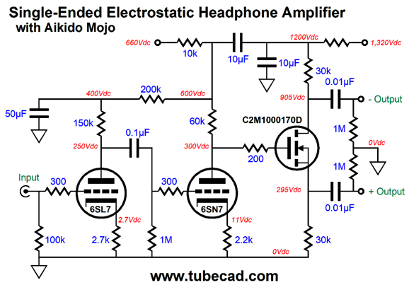
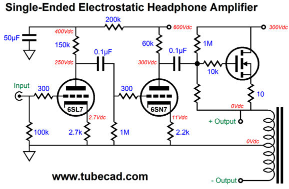
Because the split-load phase splitter offers a gain of close to unity (or almost two, depending on your perspective), we will need a high-gain, high-output frontend to drive the MOSFET to full output, i.e. about 500Vpk-to-pk. The following circuit realizes a gain of 250 (+48dB) with no negative feedback, yet offers fairly low distortion.
The 600V B+ voltage is scary, but only half as scary as the 1200V B+ voltage needed for the split-load phase splitter. (Actually, since a given voltage's wallop depends upon the square of the voltage, 600V should only be one fourth as scary as 1200V.) The 6SL7's mu of 70 followed by the 6SN7's mu of 20 got us to the high gain we needed. My only fear is that the 6SL7 may prove more microphonic than we would like. When I have built phono preamps based on the 6SL7, I found only those NOS tubes made by Mullard useable (they held pink bases), all the others were too noisy. One possible alternative is the 5691, which is super version of the 6SL7 that holds extra thick mica disks and supporting rods; moreover, the twin triode was attached to the vacuum pump for minutes, not seconds. The next step is to add the MOSFET-based split-load phase splitter.
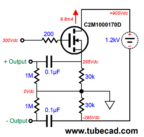
Note the DC coupling of the split-load phase splitter to the tube frontend circuit. As no negative feedback loop returns the output to the input triode, we could add a coupling capacitor without fearing instability. Why would we be tempted to do so? At startup, when the triodes are cold and not conducting, the MOSFET's gate will see at least 600Vdc, which in turn means that the two 30k resistors in the split-load phase splitter will see some voltage close to 600Vdc, resulting in 12W of dissipation per resistor. In contrast, with the coupling capacitor in place, they would experience only a 300V voltage drop and 3W of dissipation. Speaking of these resistors, they require a power rating of 12W, even with the added coupling capacitor, just in case the MOSFET fails (unlikely, but burning resistors are huge pain). I would see if Mills makes a 12W non-inductive wire-wound power resistor in 30k value. Failing that, I would use either six 2W or twelve 1W resistors in a series-parallel arrangement If we gave each channel its own floating high-voltage power supply, we could use the following arrangement, which would allow us to use lower-voltage coupling capacitors.
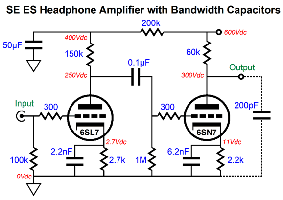
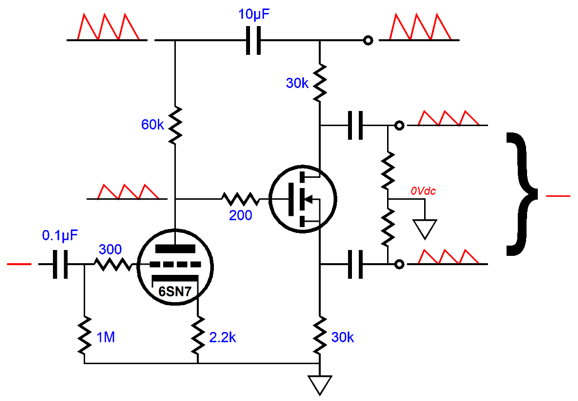
While the C2M1000170D's 200pF of input capacitance is a fraction of the typical high-voltage MOSFET, it is still fairly high, considering that the electrostatic headphones present 270pF. I ran several SPICE simulations on the driver circuit and I found that the high-frequency bandwidth's -3dB frequency occurred at about 16kHz, when driving a 200pF load. The workaround is to add some small bypass capacitors across the cathode resistors.
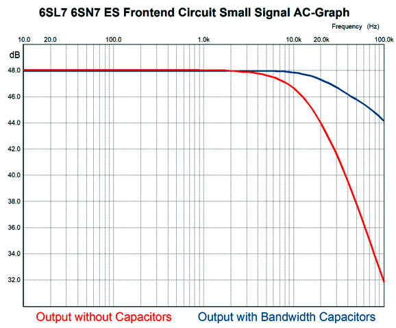
If we add too much capacitance, we will get high-frequency peaking. The capacitors only take effect at high frequencies, where their impedance drops, causing the stage's gain to increase. In SPICE simulation, the values shown above worked well. Here a graph showing their effect compared to naked cathode resistors.
With the capacitors in place, the high-frequency bandwidth's -3dB occurred at about 77kHz while driving the 200pF load. Perhaps the actual effective capacitance will prove greater, as the 200 PF may mostly be due to gate-to-source capacitance, which means it will effectively double due to Miller-effect capacitance increase. At some point, we must leave simulations behind us and attend to reality. This is probably one such example. As the circuit stands, it relies on the two B+ voltages, 600Vdc and 1200Vdc, to be noise-free, as the split-load phase splitter offers an insanely poor PSRR at the plate (or drain or collector), basically none. Alas, high-voltage power supplies are seldom noise free. We could employ RC and LC filters, and we might even try adding high-voltage regulation. On the other hand, we could get clever and throw in some Aikido mojo.
The capacitor that bridges the 600V and 1200V power-supply rails injects all of the higher voltage power-supply rail noise into the top of plate resistor and 50% at its plate. This half portion of ripple will pass out of both the non-inverting output and the inverting output, where the differential nature of the electrostatic headphones will largely ignore it.
This is an example of cleverness matching or beating brute force.
Inductor-Loaded Single-Ended Output Stage
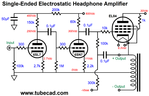
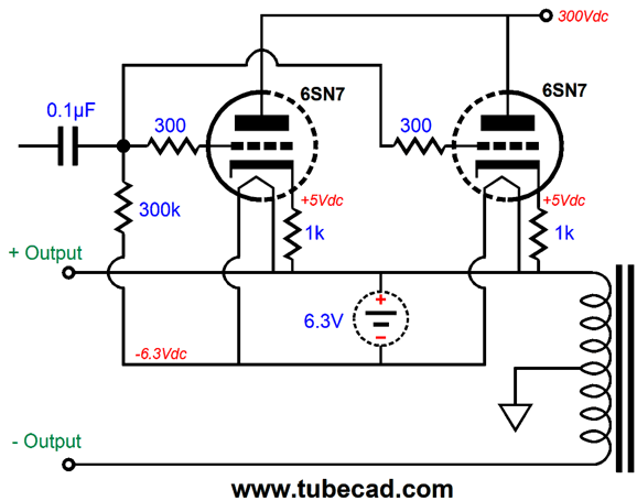
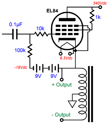
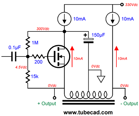
Note that the center-tap is grounded and that the entire idle current must flow through only half of the inductor's winding and it must flow unidirectionally, which means the inductor must be designed for DC current flow and must hold an air-gap in its core. The EL84's 100k grid resistor is bootstrapped by the 0.1µF capacitor, effectively making its resistance much higher. The B+ voltage is a modest 300Vdc, which means we could use robust twin-triode tubes, such as the 6BL7, 6H30, 6SN7, 12BH7, and ECC99. Since the single-ended output stage must idle at twice the current that a single triode would in a push-pull output stage, we could double up on 6SN7 triodes.
We must employ an input coupling capacitor on the output stage. Note that a floating power supply powers the heater element and that this power supply attaches directly to the non-inverting output. In addition, the 6.3Vdc power-supply voltage partially biases the 6SN7 triodes, the other portion of bias voltage coming from the 1k cathode resistors. Each channel must get its own independent and floating heater power supply. By the way, we can get clever with batteries to make floating grid-bias power supplies.
The big problem is finding a center-tapped inductor of sufficient quality and sufficient inductance. My quick estimate is that a 10H inductor would be needed. Here is the problem: conventional power-supply chokes are designed to work well with 100Hz or 120Hz ripple, but not so well with lower or higher frequencies. Switching-power-supply inductors are designed to work well with frequencies well above 20kHz, but not so well with 20Hz. Ideally, we would want an inductor made with the same core material used in high-quality audio output transformers. Why not use the primary of an audio push-pull output transformer, such as the 10W Hammond 1608A? We could try it, as the 10mA current flow might prove light enough not to saturate the core. (The I & E iron laminations, along with sloppy manufacturing, produce a small but implicit air-gap in the core.)
On the other hand, if we could find a single-ended audio output transformer with a center-tapped primary, this transformer would prove ideal. Unfortunately, if the primary offers any taps, it is usually an ultra-linear tap, which occurs between 20% to 40% of the primary, not 50%. What would we do with the secondary? We could just tape it up and forget about it. Or, we could use it to drive low-impedance headphones. (We would have to choose one type of headphones to drive at a time, as we could not drive both types at once.) It just might work. I will have to think about this arrangement some more. Returning to the center-tapped inductor, if we use higher transconductance triodes or a triode-connected pentode, the center-tapped inductor would see a far lower impedance, so less inductance would be needed. For example, a triode-connected fixed-bias EL84 would offer one-fourth the output impedance of the two 6SN7 triode in parallel with unbypassed cathode resistors. Another possible output device would be a high-voltage SiC power MOSFET, such as the C2M1000170D which was mentioned in the previous section.
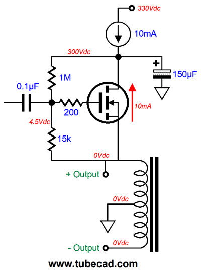
On its own, the MOSFET exhibits an output impedance of about 1 ohm, but with the 10-ohm source resistor, the final output impedance would be about 11. The source is there to provide a means of measuring the current flow through the MOSFET and to make setting the idle current less finicky. Can we find a way to get rid of the source resistor? How about this approach, which uses a constant-current source in series with the raw B+ voltage.
Dang sneaky, don't you think. The constant-current source will pull up the extremely well filtered B+ voltage until the MOSFET achieves the target idle current. This auto-bias scheme would prove a bad idea in a high-current output stage, but with the relatively weak 10mA idle current flow, it works quite well. Mind you, each channel's MOSFET must get its own high-voltage constant-current source. (Of course, if the two MOSFET were tightly matched, one 20mA constant-current source could be used. My understanding is that modern MOSFET production is producing naturally tightly matched MOSFETs, as long as they come in the same shipping tube.) As I look at the center-tapped inductor, I worry about the half that remains current free. In general, flapping windings are potential headache producers. True, the bottom half terminates in the electrostatic headphone's 270pF of capacitance. But that isn't much. Ideally, it would see a P-channel MOSFET's source. Alas, such a device does not exist and if it did, we would lose the single-ended aspect of the design. One workaround would be to force current through the bottom half of the center-tapped inductor.
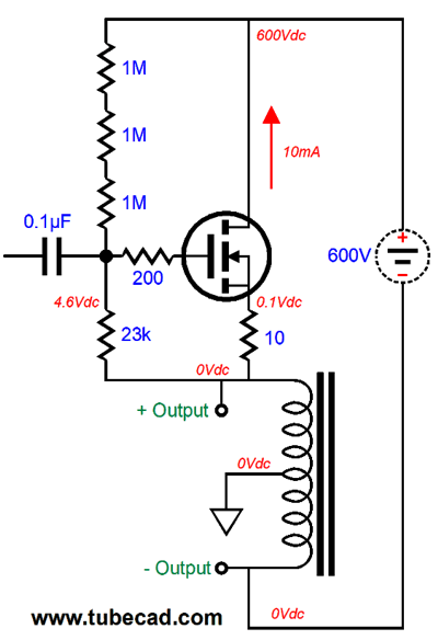
The power supply is no longer fixed, as it floats with the output signal. Much like a circlotron output stage, this arrangement requires that each channel gets two floating high-voltage power supplies. In addition, the power supply voltage has doubled. Another possible workaround would be to use a second constant-current source with the single and low-voltage power supply.
The bottom half of the choke undergoes the same current flow as the top half, but in different directions; thus, the inductor's core experiences no net DC unidirectional current flow, so no air-gap is required and we could use a tighter magnetic core structure, such as a toroid. The high-voltage constant-current source would need to survive at least 600Vdc, as the bottom half of the inductor's winding will swing up and down 250V. I would try an IXCP 10M90S (rated for 900V) constant-current source with a 330-ohm source resistor. One possible problem is its source-to-drain capacitance. On the other hand, it's possible that I am needlessly worrying about the bottom half of the winding flapping about. My thoughts return to the Hammond 1608A push-pull output transformer and driving dynamic low-impedance headphones with the secondary.
The transformer's nominal plate-to-plate impedance is 8k and its secondary offers 16-, 8-, and 4-ohm output taps. As only half of the primary is driven, the nominal primary impedance falls to 2k. (If you half the winding ratio, you quarter the impedance ratio.) If we divide 2000 ohms by 4 ohms, we get 500, which is the impedance ratio between the 4-ohm output tap and half the primary winding. To find the current step-up ratio, we take the square root of 500, i.e. 22.36, which we express as 1:22.36. For example, the 10mA if primary idle current gets stepped up to 223.6mA at the 4-ohm tap. At the same time, the voltage step-down ratio is 22.36:1, so the 22.36 volts of primary voltage swing reduces to 1 volt of swing at the 4-ohm output tap and ground. If we attach 32-ohm headphones across the 4-ohm tap and ground, the reflected impedance at the primary will equal 500 against 32 ohms, or 16k. The idle current of 10mA against 16k equals a peak voltage swing of 160Vpk, which divided by 22.36 equals 7.15Vpk into the 32-ohm load, which in turn implies 800mW of power. The math is interesting, but I wonder if the transformer offers enough inductance for the 32-ohm load, as it is 8 times higher than the intended load impedance.
Hybrid Electrostatic Headphone Amplifier
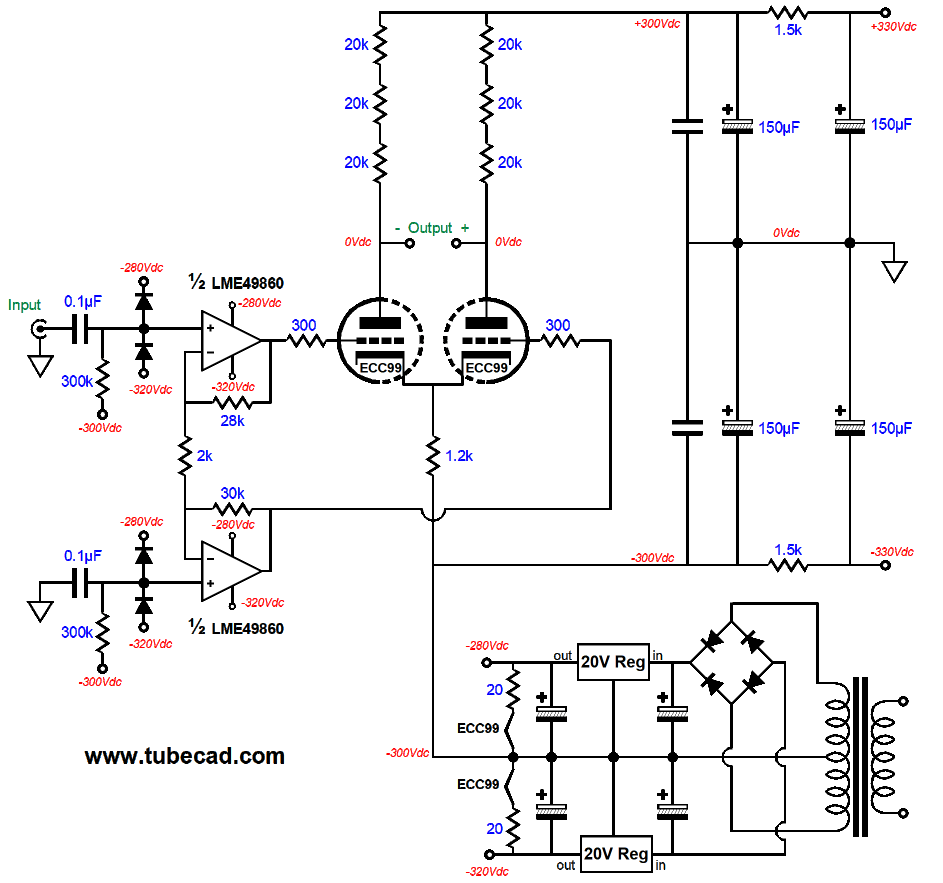
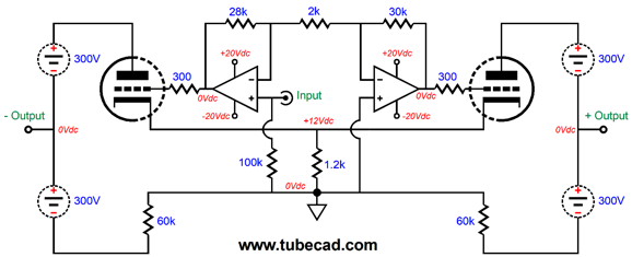
The big problem is that OpAmps usually run on +/-12Vdc power-supply rails, while the output triodes require something closer to +/-16Vpk voltage swings at their grids. A second problem is that with a high-voltage bipolar power supply, the triode grids located at the negative power-supply rail voltage, say -300V, while the input signal to the electrostatic headphone amplifier is ground referenced. Starting with the first problem, the OpAmp's low power-supply voltages. A few higher-voltage OpAmps are made. One dual-amplifier OpAmp that readily comes to mind is the LME49860, whose positive and negative power-supply pins can span 44V; in other words, +/-22Vdc. In addition, it offers low distortion and noise (2.7nV/√Hz) and whose output can swing to one volt of the power-supply rail voltages. Solving the second problem, having the triode grid near the -300V power-supply rail voltage, requires capacitor coupling both the input signal and the signal ground. In other words, we can reference the bipolar power supply to the -300V power-supply rail and use coupling capacitors to shield the OpAmp's inputs from the 300V differential.
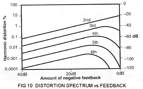
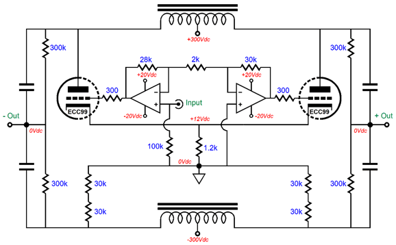
Click on schematic to see enlargement The unbalanced input signal and its ground are DC isolated by the two 0.1µF coupling capacitors. The four diodes protect the OpAmp inputs from excessive voltages as the coupling capacitors charge up. (In fact, I would place four more diodes on the other side of the coupling capacitors to protect the signal source.) The two OpAmp amplifiers put out equal output signals in anti-phase. The top amplifier's functions as a non-inverting amplifier and its gain is set by (28k + 2k)/2k or 15; the bottom amplifier is inverting and its gain is set by 30k/2k or 15. The negative feedback loops are confined to the OpAmps. Why not extend the loops to encompass the triode outputs? It wouldn't be easy, but it could be done. I, however, wouldn't bother. Why not? My first electrostatic headphone amplifier was an all-tube effort that used two global negative feedback loops from the outputs to the input stage. I experimented with zero negative feedback and much preferred the sound. More relaxed and effortless sounding. Recently, I ran several SPICE simulations on that old circuit and I saw that while the THD did drop a tad, the higher harmonics rose relative to the feedback-free version. I was instantly reminded of the famous graph from Peter Baxandall that showed that the 2nd harmonic goes down linearly with feedback, however all the higher order harmonics first go up and then fall with increased feedback. In other words, unless you are employing gobs and gobs of negative feedback, the feedback will probably make things worse.
With an all-tube electrostatic headphone amplifier, we do not realize all that much negative feedback. In contrast, with an OpAmp frontend, we would be using the OpAmp's considerable open-loop gain to power the negative feedback. In short, I would want to hold a shootout between this circuit and a full negative feedback design. By the way, the +/-20V bipolar power supply is only roughly sketched out. Here is the full version.
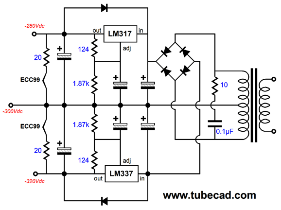
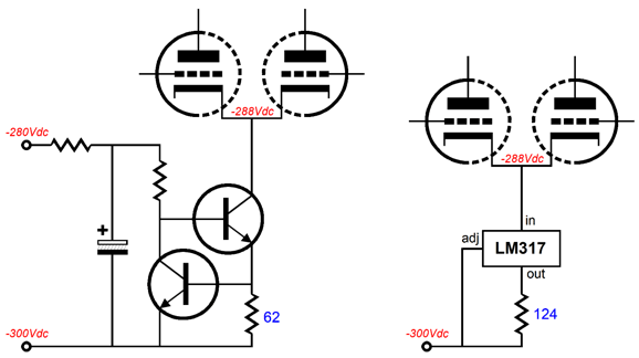
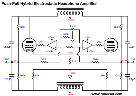
Note how the two ECC99 heater elements are also powered by the OpAmp's bipolar power supply. In fact, the series 20-ohm resistor will prolong the tube's life span, as they limit the current inrush at startup, when the heater element presents a far lower resistance than when it is hot. Can we further hot-rod this design? (Surely, you know that I wouldn't ask if I didn't believe it possible.) Note that the two ECC99 triode share a common cathode resistor. We could replace the 1.2k resistor with a 10mA constant-current source, which would lower the distortion and shield the cathodes from the negative power-supply rail ripple. We could use an LM317-based constant-current source or we could go the discrete route and use two transistors.
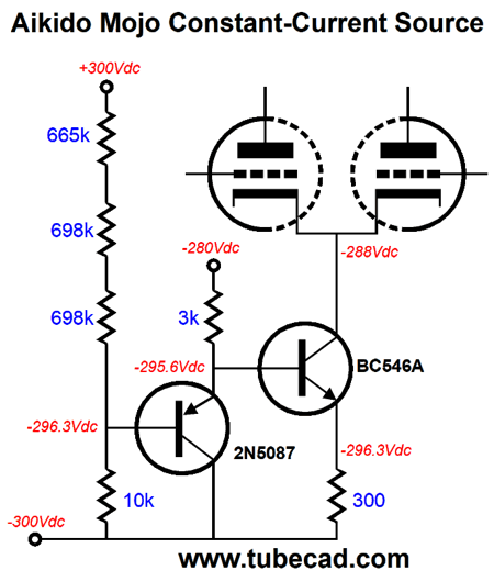
Both designs would work well. Note, however, that by replacing the shared cathode resistor with a constant-current source all the positive power-supply rail ripple will appear at the two outputs. Is this a problem? If you are only driving electrostatic headphones, no, as the common-mode noise will be ignored by the headphones. If you plan on also having the option of driving a cathode follower output stage, then it could prove a problem, depending on if the power amplifier output stage runs in class-A or class-AB. Well, after staring at the circuit, I came up with an interesting Aikido mojo constant-current source.
This constant-current source also modulates the current flow in response to the positive power-supply rail ripple, so that the ripple nulls at the two outputs. Dang sneaky, I must admit.
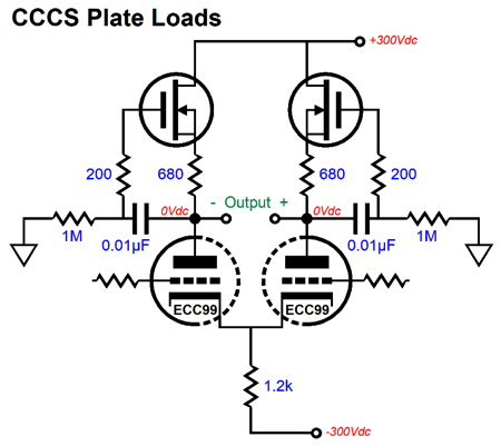
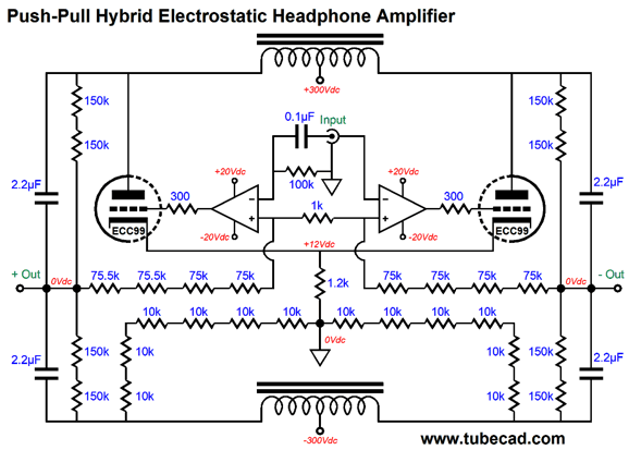
Is there any other possible hot-rod modification? We could replace the string of plate resistors with constant-current sources. Placing constant-current sources in series seldom works out, however. In other words, if we use constant-current source loads for the plate, I would not use a constant-current source in place of the 1.2k shared cathode resistor. One workaround might be to use two of my compliant-constant-current sources (CCCS), which do not draw a fixed amount of current but rather they conform to the existing current flow, while presenting a high impedance, much like an inductor, but with the difference of dropping a great deal of voltage at idle. The potential problem is extra capacitance, something the resistors sidestep. In addition, constant-current-source loading will by necessity increase the output impedance. Normally, this might not be a big deal, but when driving a capacitive load it becomes a big deal.
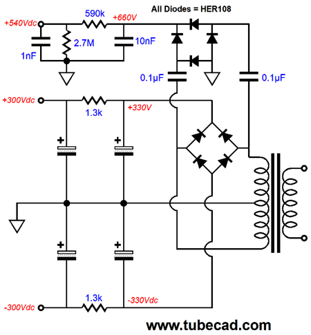
Even without the fancy Aikido mojo constant-current source, this circuit would probably make 99% of ears happy. I am tempted to lay out a PCB for the design, which would include all the power supplies. Not shown so far is the voltage-doubler circuit needed to create the 580Vdc bias voltage for the electrostatic headphones.
I am guessing that all of it, including two channels, would fit on a PCB 6 inches by 7 inches.
Thinking Outside the Conventions
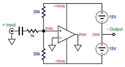
The single OpAmp's output is grounded, which would normally be a tragedy, but isn't in this case due to the floating bipolar power supply. This amplifier is an inverting type, in spite of the input signal being delivered to the OpAmp's non-inverting input. If the output drifts too positive, the OpAmp's non-inverting input will see the positive movement through the two 30k resistors, causing the OpAmp's output to try to swing positively a seeming impossibility. What will happen is that the top half of the output stage will draw more current, while the bottom half draws less, causing the floating bipolar power supply to be pulled down in voltage, bringing the output back at ground potential. The amplifier's gain is 15, as the two 30 feedback resistors are effectively in parallel with each other, making a 15k resistance in AC terms. I know that this topology look crazy to many, but it is actually used in some highly-regarded power amplifiers, as it allows the designer to use a low-voltage OpAmp to drive a grounded compound-feedback output stage to high output voltage swings, something the low-voltage OpAmp could never do with a conventional emitter-follower output stage.
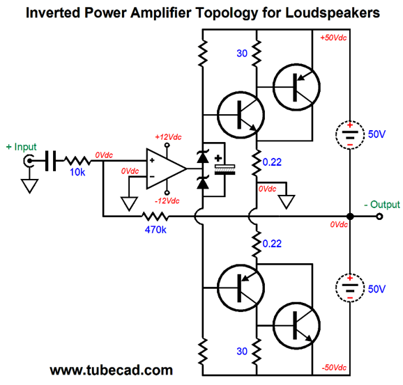
Note how a single 470k feedback resistor has replaced the two 30k negative feedback resistors. The makers of such a power amplifier have concluded that the hassle of one floating bipolar power supply per channel is outweighed by the by ease of using an OpAmp in the amplifier frontend, saving in cost and complexity compared to the usual discrete frontend of input stage and VAS stage. In addition, the auto-bias feature only makes such a topology more appealing. Okay, but how do we get from here to an amplifier capable of directly driving electrostatic headphones? Here is half of the answer.
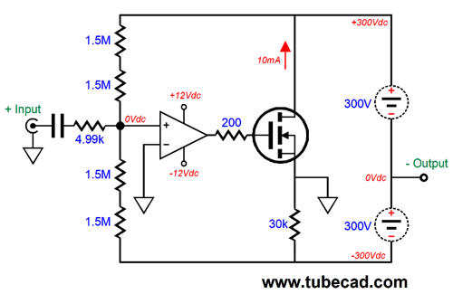
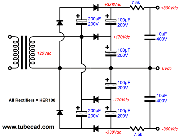
Two of these stages, one inverting and one non-inverting, are needed to drive one channel. The OpAmp controls the high-voltage MOSFET's current conduction ad the floating bipolar power supply will swing up and down based on the MOSFET's current conduction. If the MOSFET cuts off completely, the output will slam to +300V; if it conducts twice its idle current, the output will slam to -300V; but at 10mA, the output will center at 0V. The floating power supply could be made from a center-tapped 480Vac winding or from a single 120Vac winding.
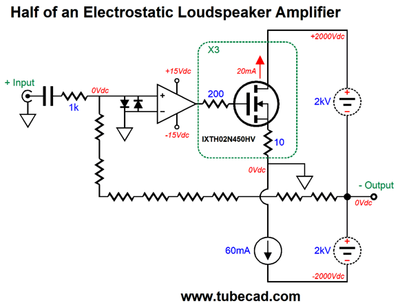
Other than the two 10µF/400V capacitors, all the capacitors are rated for 200V. In fact, we can scale up the bipolar power supply rail voltages to make an amplifier capable of driving electrostatic loudspeakers.
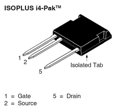
The IXTH02N450HV high-voltage MOSFET can withstand 4500V and is rated for 115W. In addition, its input capacitance is a low 246pF. The MOSFET comes in the high-voltage TO-247HV package, which puts a big space between the source and drain.
The many negative feedback resistors in series are needed so as not to exceed the resistor's voltage limit and to lower voltage-induced distortion from the resistors. The constant-current source would be made from three IXTH02N450HV high-voltage MOSFETs. In other words, one channel would require 12 MOSFETs and two OpAmps. Think about how amazing it is to have an OpAmp running off of +/-12V power-supply rails drive the MOSFETs to close to 2kV of output voltage swing—all in class-A. Okay, let's now return to the world of +/-300V power-supply rail voltages and driving electrostatic headphones and tubes. We do not have to use a high-voltage MOSFET, as we could use a triode in its stead. We will take baby steps.
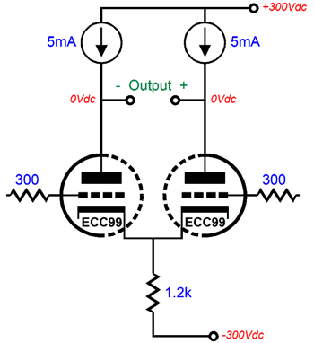
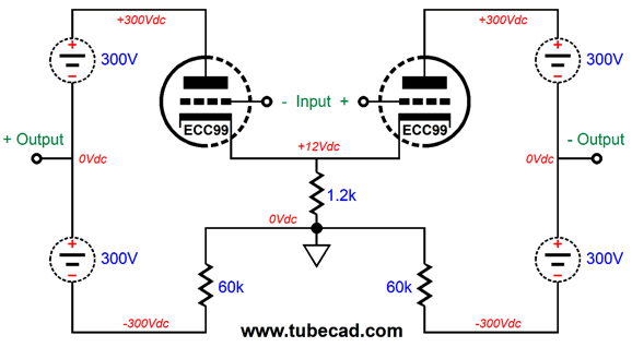
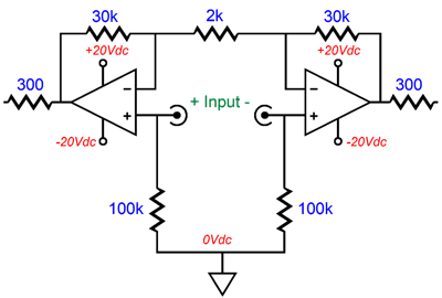
This is the basic topology. The triode's grids are at ground potential (i.e. 0Vdc) and share a cathode resistor that terminates into ground. A balanced set of input signals drive the triodes in anti-phase.
In terms of PSRR, this topology yields a power-supply noise null at each output, if the positive and negative power-supply rails hold equal but anti-phase ripple.
Now, all we have to do is add the two OpAmps needed to drive the triodes.
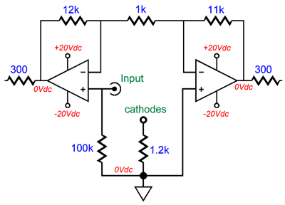
Note how the OpAmp outputs are centered at 0V and how the 1.2k shared cathode resistor cathode biases the triodes. The three resistors in the negative feedback loops set a gain of +/-15 from the OpAmps, which the triodes will increase to +/-250V at the outputs. Note that no coupling capacitors were used at the input or between OpAmps and the triode grids. We can use a balanced set of input signals with this small modification.
All in all, this is an interesting circuit, but the next step will make it even more so. The needed four floating high-voltage power supplies for stereo is a pain. The workaround would be to use a single bipolar power supply.
Each channel uses two center-tapped inductors to AC eliminate the need for floating power supplies and separate the triode-portion of the circuit in AC terms from the high-voltage bipolar power supply, while providing two DC current paths. The four 300k resistors help the output coupling capacitors split the voltage differential, resulting in a ground-potential output. Where do we buy the center-tapped inductors? I know that Hartley oscillators used a center-tapped inductor, so they must have been made. My prediction is that they will be hard to find. A workaround might be to use a flat-pack power transformer.
Note how the four windings are wound on four separate bobbins. In other words, the windings do not lie atop each other. This is important, as it increases the voltage isolation between windings and decreases the capacitance between windings.
The Triad FP230-50 flat-pack transformer holds two 115Vac primaries and two 115Vac secondaries and is rated 12VA and 50mA. I happen to own a few of them. I need to set up a test rig to see if they can be used. If they can, we would only need one per channel. What if we want the OpAmp's negative feedback loop to encompass the outputs? We might try this arrangement.
Note how we had to flip the OpAmp inputs, as the triodes will invert the OpAmp's output. The negative feedback resistors now terminate at the two outputs. I am inclined to think that this setup would not work with perfect center-tapped inductors that presented no DCR. But as real inductor are made from long lengths of wire, some DCR is always present. What happens when the tube is missing from its socket or when the cathodes are cold and not emitting electrons? Both outputs will climb slightly positive, as current will still flow through the two 60k resistors and the bottom center-tapped inductor winding, creating a voltage drop across the winding's DCR, which will not be matched from the top center-tapped inductor, so a small positive DC offset will arise. The OpAmps will slam their output to the positive rail voltage, which isn't ideal, at least when the tube is warming up, as we risk potential cathode stripping. The workaround is to pre-heat the tube heater elements prior to applying the bipolar power supply voltages. Okay, let's now flesh out the design.
Many resistors in series! Had I shown this schematic first, many would give up hope of understanding it. By the way, just because this is the last version shown does not mean that it is the circuit I deem to be the best. In fact, I am fairly certain that I would prefer the previous version that didn't include the outputs in the OpAmp negative feedback loops. It would be a fun shootout to hold between the two versions. The problem is that two different PCBs would have to be laid out, as this version flips the OpAmp inputs. Quick Update: I just tried running simulations on the circuit above. I could only get half of it to work. In other words, it worked well in SPICE only when only one OpAmp and one triode was used. In contrast, the version that contained the feedback loops to the OpAmps worked perfectly. One thing I discovered was that the ECC99 offers so much more transconductance than a 6SN7 that less gain is needed from the OpAmps. For example, here is a revised OpAmp setup if the ECC99 is used.
One volt of input signal prompts +/-12V of peak output from the OpAmps. This means we can drop the bipolar power supply rail voltages to just +/-15Vdc, which allows us to use many more OpAmps. I happen to like the OPA2107, a FET-input dual-amplifier OpAmp. Alas, it isn't cheap. Okay, I have gone over 5,000 words, which is insane by any measure. Merry Christmas.
Winter Music Recommendations
Well, I found anther hit in Katie Melua's album, In Winter. Only a few of the songs count as Christmas music, the others being only winter themed.
Here is an excellent review from a professional music critic, Matt Collar at AllMusic.com.
Yes indeed. For those that are not so irked by kitschy Christmas songs, Eric Clapton's album, Happy Xmas, is a fun listen. Clapton obviously had a lot of fun with this album. For example, he turns the classic song, Silent Night, into a Reggae number.
Nonetheless, much like a good comedy album, hearing it once a year will be enough for me. Both albums are offered by Tidal in the MQA format. Merry listening.
//JRB
User Guides for GlassWare Software
For those of you who still have old computers running Windows XP (32-bit) or any other Windows 32-bit OS, I have setup the download availability of my old old standards: Tube CAD, SE Amp CAD, and Audio Gadgets. The downloads are at the GlassWare-Yahoo store and the price is only $9.95 for each program. http://glass-ware.stores.yahoo.net/adsoffromgla.html So many have asked that I had to do it. WARNING: THESE THREE PROGRAMS WILL NOT RUN UNDER VISTA 64-Bit or WINDOWS 7 & 8 or any other 64-bit OS. I do plan on remaking all of these programs into 64-bit versions, but it will be a huge ordeal, as programming requires vast chunks of noise-free time, something very rare with children running about. Ideally, I would love to come out with versions that run on iPads and Android-OS tablets.
|
I know that some readers wish to avoid Patreon, so here is a PayPal button instead. Thanks. John Broskie
John Gives
Special Thanks to the Special 83
I am truly stunned and appreciative of their support. In addition I want to thank the following patrons:
All of your support makes a big difference. I would love to arrive at the point where creating my posts was my top priority of the day, not something that I have to steal time from other obligations to do. The more support I get, the higher up these posts move up in deserving attention.
If you have been reading my posts, you know that my lifetime goal is reaching post number one thousand. I have 513 more to go. My second goal was to gather 1,000 patrons. Well, that no longer seems possible to me, so I will shoot for a mighty 100 instead. Thus, I have 17 patrons to go. Help me get there.
Support the Tube CAD Journal & get an extremely powerful push-pull tube-amplifier simulator for TCJ Push-Pull Calculator
TCJ PPC Version 2 Improvements Rebuilt simulation engine *User definable
Download or CD ROM For more information, please visit our Web site : To purchase, please visit our Yahoo Store: |
|||


| www.tubecad.com Copyright © 1999-2019 GlassWare All Rights Reserved |