| John Broskie's Guide to Tube Circuit Analysis & Design |
|
03 October 2020 Post 515
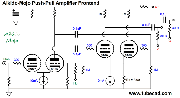
Aikido Mojo Push-Pull Frontend
The larger the negative power-supply-rail voltage, the closer the long-tail resistor approaches constant-current source performance. Today, we can use an actual solid-state constant-current source, which need not terminate into a negative power-supply rail. (By the way, in SPICE we use constant-current sources, in reality we use current regulators. A true constant-current source would deliver current on its own, much in the same way that a battery delivers voltage on its own.)
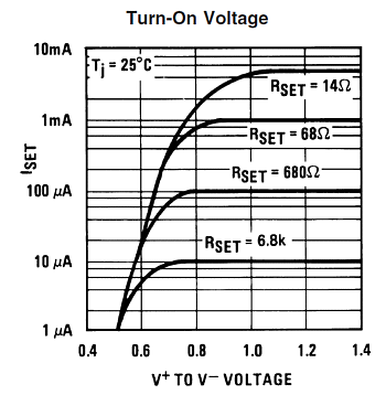
The 6SN7's relatively low amplification factor (mu) of 20 means that we can get away with terminating the constant-current source into ground. The lower the mu, the higher the cathode voltage. By the way, the formula for the needed cathode voltage for a given plate voltage and desired idle current is Vk = (Vp - rp·Iq) / (mu + 1) Where Vk is the cathode voltage; Vp, the plate voltage; rp, the plate resistance; and mu, the triode's amplification factor. From this formula, we can readily see that high mu necessitates a low cathode voltage. How much cathode voltage is needed? The following graph from the LM334 datasheet shows that about 1.5V of voltage drop is needed across it at 10mA.
To this voltage, however, we need to add the expected input signal swing, which is typically 1Vpk; thus, 2.5V is minimum.
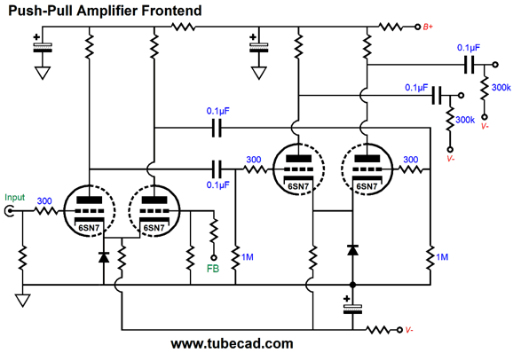
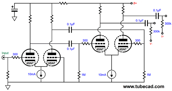
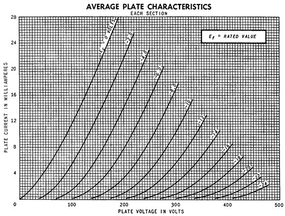
Leaving the formula behind, I did a quick inspection of the 6SN7 plate curves, and I found that at 5mA and 120V of plate voltage, the grid voltage was -3V. Since this differential stage sees a balanced input signal, the two conjoined cathodes do not move much at all, so we can get away with the relative low +3V cathode voltage. Our last step is to take 120V and subtract it from the B+ voltage for the input stage, we then divide the result by 0.005A to find the needed value for the plate resistors. For example, if the B+ voltage available to the driver stage is 400Vdc, we would subtract 120V from 400V and get 280V as plate resistor voltage drop; next, we divide 280V by 0.005A (one half of the constant-current source idle current) and get 56k for the resistor value. Here is a quick aside: many become stuck on resistors; they want to use one resistor at all times; and they panic when a desired resistor value is not made, such as 3180 ohms. The workaround is either to place two lower-value resistors in series or to place two higher-value resistors in parallel. For example, we could use a 3k and 180-ohm resistors in series; or, if we desired equal heat dissipation, we could use 1.6k and 1.58k resistors. If we went the parallel-resistor route, we could use 3.32k ohms and 75k resistors in parallel. Well, with a plate resistor value of 56k and a 280V voltage drop, the resistor will dissipate 1.4W, so we should at least use a 2W resistor. On the other hand, if we place four ½W 56k resistors in series-parallel, we effectively get a 2W 56k resistor. If we use 1W resistors, we get a 4W 56k resistor. Moving to the differential driver stage, we should up the plate voltage to something closer to 200V to ensure that the constant-current source gets enough voltage headroom. (Remember, the higher the plate voltage, the higher the cathode voltage must be to maintain the same idle current flow.) After inspecting the 6SN7's plate curves, we see that a cathode voltage of 6.5V is needed to establish an idle current flow 5mA with 200V plate voltage (actually with the plate voltage equaling 200V – 6.5V, which gives us the cathode-to-plate voltage). If the input stage's B+ voltage is 350Vdc, we get 150V as the plate-resistor voltage drop. We divide 150V by 0.005A and get 30k. This resistor will dissipate 0.75W. What I have shown you is the procedure needed to work out all the part values, which explains why I didn't label all the part values. The next step would to either use a SPICE simulation or a hand calculator and formulas to find all the important performance data, such as gain, bandwidth, distortion, and PSRR. My quick guess would be that the input stage would yield a gain of slightly less than 10, while the driver stage would deliver slightly more than 10, say a gain 0f 8 and 12, which combine to equal about 100—except that the driver stage is driven by a balanced signal, which effectively doubles its gain, so something close to 1:200 would be my final guess. SPICE didn't agree. I just ran a SPICE simulation and the gain came in at 1:142, with -/+1Vpk of balanced input signal; and 1:284 in differential output. On the other hand, SPICE did confirm the cathode voltages I had gleaned from inspecting the 6SN7 plate curves, with voltages of 6.56V and 2.82V. Okay, now it's time for my signature addition of Aikido mojo.
Note that both the input and driver stage share the same B+ voltage. Next, note that the driver stage's constant-current source is shunted by a resistor. Why? This resistor effectively sees 100% of the power-supply noise, as the input stage exhibits almost no PSRR. How do we find this resistor's value? The quick answer is half the driver stage's plate resistor value, in this example 56k. The slower, more accurate answer is that we must include the actual input stage PSRR and include the 6SN7's relatively weak transconductance, which means that not all the power-supply noise presented to the driver stage grids will be imposed on the added resistor. In other words, the resistor will need to be slightly less in value than what the quick answer supposed. In SPICE simulations, with input-stage plate resistors of 47k, the optimal resistor value was 25.5k, which resulted in a PSRR of over 40dB, far better than the stock -0.47dB. Even the quick answer value of 28k was far better, coming in at -21dB. Moreover, this Aikido mojo version resulted in more gain, as the input stage got a higher B+ voltage and larger in value plate resistors, resulting in a gain of 1:154 and 1:308 differentially. Is an improvement in PSRR really all that important? Dang yes. The huge disadvantage tube-based audio gear faces in competition with solid-state gear is poor PSRR. If solid-state equipment sounds more detailed it is due to it being less noisy. The quieter tube equipment becomes the more subtle details surface. Thirty years ago, a friend borrowed my tube-based headphone amplifier so that he could evaluate low-noise transistors in his MC phono preamp, as the tube headphone amplifier allowed him to hear better the noise characteristics of individual transistors. This is the way it should be. In addition, the quieter the tube equipment is the lower the playback volume needs to be, as we do not have to crank up the sound level to get past the noise.
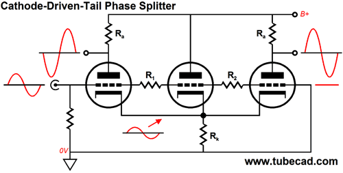
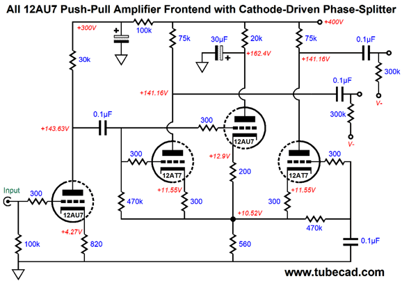
Frontend with Cathode-Driven Phase Splitter
While I pondered possible frontends to the transformer-coupled circlotron, I remembered my cathode-driven phase splitter design from post 297. The idea behind this phase splitter is that we deliver two input signals to a differential amplifier: one for the input triode's grid and one for the tied cathodes, the latter being half the former's magnitude.
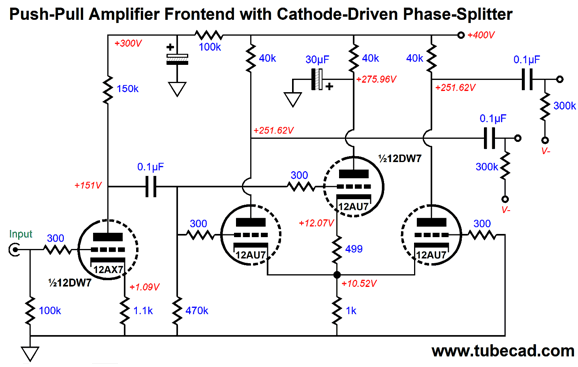
This frontend uses 12DW7 and 12AU7 tubes. The 12DW7/7247/ECC832 is a dual-triode tube that holds dissimilar triodes, a 12AX7 and 12AU7 type. The 12AX7 is used as the input tube in a grounded-cathode amplifier configuration. The 12DW7's 12AU7 triode is used to drive the coupled cathodes with a signal half the magnitude of the input signal to the differential amplifier. The 499-ohm and 1k cathode resistors seem to make a poor two-resistor voltage divider, but we must include the two 12AU7 triode cathode impedances in our calculations, as they are effectively in parallel with the 1k cathode resistor. By the way, 1k is not much of a long-tail resistance value, but it need not be, as the tied cathodes are being driven. In general, I have given up on the 12AX7, as it often has proved to be the weak link. Other high-mu tubes are the 6SL7, 12AT7, 5751, and 12BZ7, which is a 12AX7 with half the plate resistance. I like the 12BZ7 a great deal, but it is rare. I have always gotten good results from the 12AT7, so I decided to use it instead. In addition, I decided to keep the 12AU7 as the input triode and as the cathode-driving triode.
Note the addition of the extra 470k grid resistor and 0.1µF capacitor. Why? The 12AT7 requires a far lower grid-bias voltage than the 12AU7.
Hybrid Cross-Coupled Amplifier
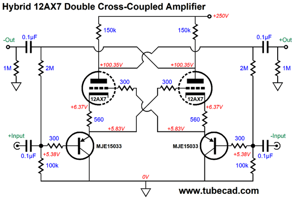
Well, the circuit I found replaces the cathode followers with emitter followers based on PNP transistors.
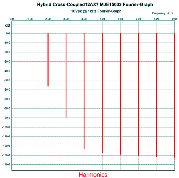
This is a doubled-crossed cross-coupled circuit in that the AC signal is cross-coupled at the triodes, and the DC idle current is monitored and cross-coupled at the transistor bases. Much like the garter-belt biasing of output tubes in a push-pull power amplifier, the cross-coupling of the plate voltage to the opposing PNP transistor's base through the 2M resistors works to equalize the idle current flow between left and right triodes. For example, if one side drew too much idle current and the other too little, the side that drew too much would experience a greater voltage drop across its plate resistor, which would result in the weak side's transistor seeing less base voltage, causing the weak side's cathode voltage to drop, which in turn forces the weak triode to greater conduction. At the same time, the weak side's plate was too high, due to its lower idle current flow, resulting in the strong side's transistor seeing a higher base voltage, which causes an equal rise in cathode voltage, prompting a reduction in current flow. In other words, self-balancing bias. Here is the SPICE-genrated Fourier graph of one output at 10Vpk at 1kHz.
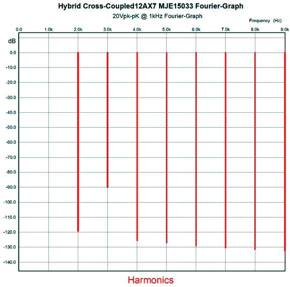
Here is the SPICE-genrated Fourier graph of the differential output, i.e. 20Vpk-pk at 1kHz.
Note that the THD dropped biggly, although the 3rd harmonic remains unchanged. The differential distortion is key, as it is what drives the output tubes. By the way, note the two input coupling capacitors. These are essential, as the transistor's base current flow is used to create the 5.36V voltage drop across the 100k base resistors. So, how well does this hybrid circuit perform?
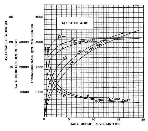
12AX7 SPICE Model As I have been pointing out for over two decades now, the SPICE models of triodes are all fundamentally flawed, as they treat the triode as a variable current source, when in fact it is a variable resistance. The correct SPICE formula must be of the form of R = X, not I = X. In addition, due to a slavish devotion to the Childs three-halves triode formula, the SPICE triode models invariably portray a triode with an absolutely constant amplification factor. Real triodes offer a varying amplification factor. The following graph shows the 6SN7's mu at three different plate voltges, 50V, 150V, and 250V. Not one of them is a straigt line.
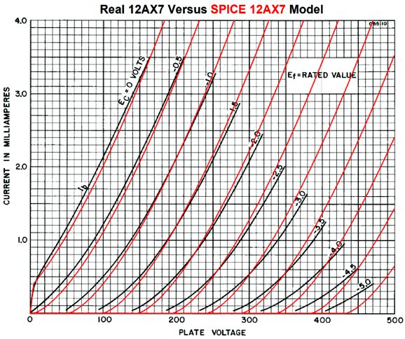
Thus, I decided to examine the SPICE 12AX7 model; I ran a set of plate curves in a SPICE curve tracer circuit on the 12AX7 SPICE model, and then I overlaid the curves over the tube manual's curves.
Well, things are actually better than I expected, although we see the flaw of a constant amplification factor. Note the bump at zero grid volts and low plate voltages. I do not believe this bump actually exists, as I could not find it with actual 12AX7 tubes run at crazy-low plate voltages, such as 12Vdc. In addition, I remember reading a review of a modern tube curve tracer and finding that the reviewer was disappointed not to see a bump when he traced the 12AX7. Where did the bump come from? My guess is that it was due to a screw-up in the test rig. Moreover, I doubt that a curve tracer was used, as commercial curve tracers postdated the 12AX7's creation in 1946. The famous Tektronix 570 was released in 1955. What did they do prior to its sale? Getting a lab tech and two power supplies with a variable output voltage, one high-voltage and one low-voltage, and an ammeter and pencil and paper was the first step. The second step was to take the spot-point data and a French curve and draw the curves over the points. See post 48 for more details on the plotting plate curves. Okay, what can we conclude here? One conclusion is that SPICE triode models suck. Does that mean that they are worthless? No. We can still use them as long as we are aware that they are not identical with reality. By the way, tube manual plate curves are not the same as reality, as you probably have never encountered a tube that perfectly matched the plate-curves graph in the tube manual; and even if you did, would it still match the graph two years later? Tubes not only vary from each other but from themselves over time. Okay, returning to SPICE triode models and their usefulness, we can use the imperfect SPICE triode models to get perfect relative evaluations of a tube circuit in SPICE simulations. For example, in a SPICE shootout of a White cathode follower versus a plain-Jane cathode follower, the White cathode follower will offer a lower output impedance in SPICE simulations—as it will in reality with real triodes. My rule of thumb is that reality will prove ten times worse in terms of THD, delivering only 0.1% instead of 0.01%.
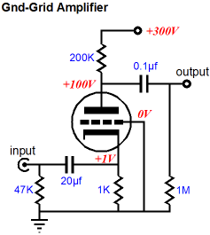
Hybrid Grounded-Grid Gain Stage
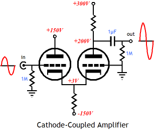
The cathode-coupled amplifier is a design workaround that uses a cathode follower to drive the grounded-grid amplifier's cathode. With the cathode-coupled amplifier we get the ground-potential and high impedance input and wide high-frequency bandwidth and no phase inversion.
Of course, the cathode-coupled amplifier also brings its own problems, such as dissimilar cathode-to-plate voltages necessitating different grid bias voltages. Well, if we replace the cathode follower with a PNP-transistor-based emitter follower or P-MOSFET-based source follower, we save on triodes and power dissipation, as the solid-state follower dissipates no more heat than a cathode resistor would.
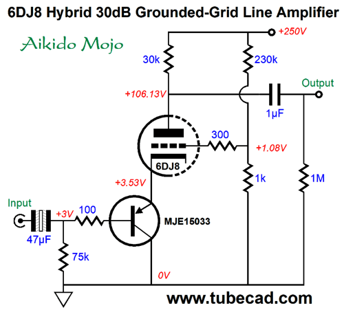
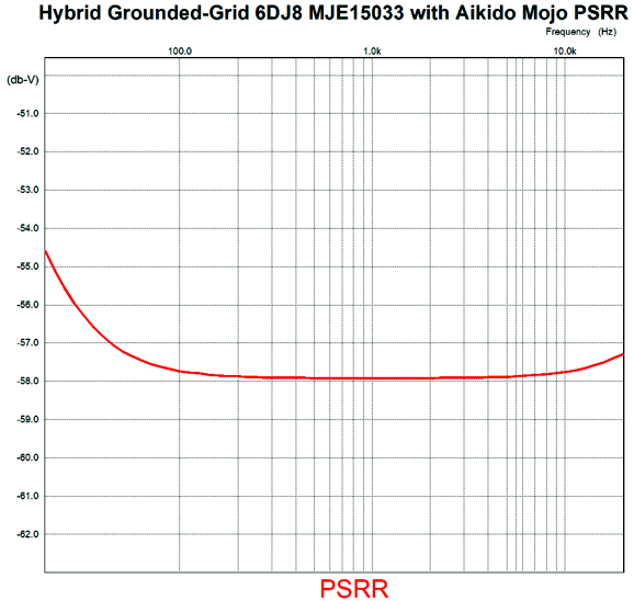
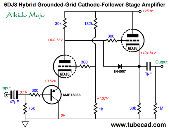
The grid is "grounded" in that it does not receive the input signal. It does, however in this circuit, see a portion of the power-supply noise. Why? Aikido mojo. Rather than let the grid go to waste, I put it use to force a power-supply noise null at the output. How well did it work?
Without the Aikido mojo, the PSRR came in at about -19dB; in other words, about 40dB worse. The 47µF input coupling capacitor may seem a bit excessive, but it is not. The larger the capacitor's value, the lower in frequency the null goes. Some will balk at the non-polarized electrolytic capacitor, preferring to use a polypropylene or PIO capacitor. I get it. However, many would be shocked to know that DACs and music servers and CD players that cost many thousands of dollars use plain electrolytic capacitors as coupling capacitors. Don't electrolytic capacitors add distortion? They do. The workaround is to use a ridiculously large value, as the distortion goes down with the increase in value. For example, if only 0.47µF is needed, they would use a 470µF electrolytic capacitor. A friend once showed me his hot-rodded FM tuner. He opened the enclosure and I beheld nothing buy Solen polypropylene capacitors, big fat caps. Too stunned to speak, I blankly stared at him. He explained that it wasn't easy getting all the capacitors in the enclosure, whereupon I regained my voice and I uttered, "Dear God, why so many caps?" He explained that he had replaced the 470µF electrolytic coupling capacitors with 470µF of polypropylene. He refused to believe me when I told him that he only needed a 0.47µF film capacitor. As he saw it, obviously the circuit designer would never have used an electrolytic capacitors one thousand times too big, so I must be an idiot. Well, he was certainly right, as only an idiot would have tried, as I did, to explain carefully the folly and expense of this project to its father. While on the topic of interesting mental perspectives, what if you are a flat-earth tube fancier, the type that disdains any part type or any part configuration in a tube circuit that his grandfather could neither recognize nor understand? Well, you would simply shunt the 1k resistor with a capacitor, which would instantly undo the Aikido mojo. But then you probably would also balk at the inclusion of the PNP transistor, even though this circuit could have been created and built 60 years ago. What if we desire a lower output impedance? The obvious solution is to add a cathode follower output stage.
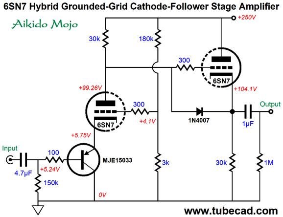
Note the change in the top resistor's value, which was lowered from 232k to 182k. Why? We need to null the power-supply noise at the cathode follower's output, so we need to inject a tad more of the ripple into the grid. For those who prefer octal tubes, here is the 6SN7 version.
The 6SN7's lower mu helped us out in this circuit, as we were able to use the 150k base resistor at the input, which in turn allowed us to use the smaller-valued 4.7µF coupling capacitor and still get a deep power-supply-noise null. The gain came in close to 1:16 and the THD was low. So what's not to like about this circuit? One potential problem I can imagine is having to hand-select and match the PNP transistors, after measuring their current gain. (By the way, the reason I used the MJE15033 transistor, which is a 40W device in the TO-220 package, was that I feared that smaller transistors would prove too susceptible to temperature changes.) One workaround would be to add a negative feedback loop that not only lowered distortion and output impedance, but would DC stabilize the circuit.
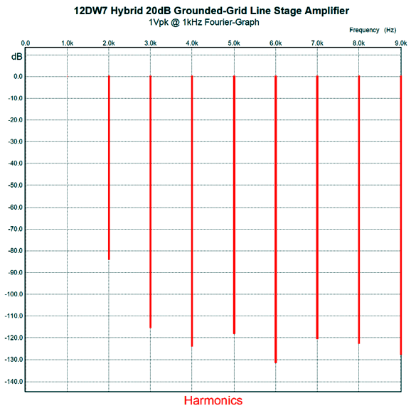
The 12DW7's 12AX7 triode delivers a high gain, which we use to power the negative feedback. The negative feedback resistors double as the cathode follower's load resistance and no internal coupling capacitor is needed. The gain is set to 1:10 (+20dB). The open-loop gain is 49 (+33.8dB), so the circuit realizes 13.8dB of a negative feedback. With the negative feedback loop in place, the THD in SPICE simulations was only 0.01% with 1Vpk of output at 1kHz; the output impedance was about 80 ohms.
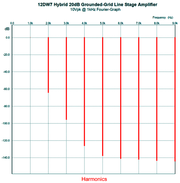
With 10Vpk of output, we get this result in SPICE.
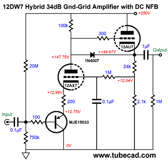
Okay, what if we renounce negative feedback in general? Well, we can keep the DC negative feedback in place, but otherwise let the input triode run wild.
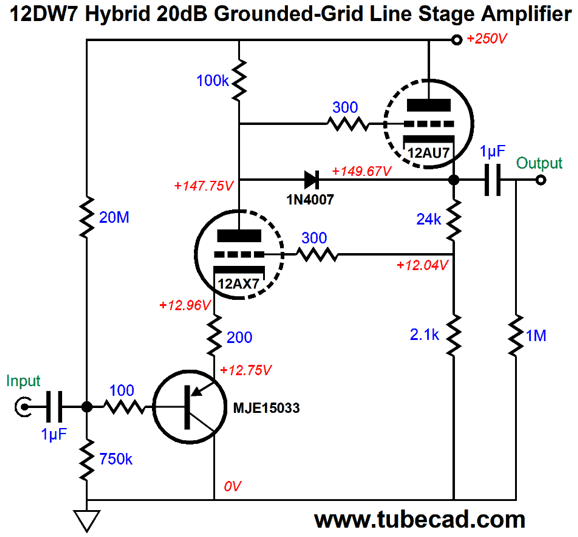
The 1M resistor and 0.1µF capacitor define an RC low-pass filter with a -3dB frequency of 1.6Hz. In other words, DC gets through freely, but those frequencies higher than 1.6Hz are attenuated by a 6dB-per-octave slope. What do you think the odds are that I would stop here, when more circuit enhancement was possible? What is missing, now that we have jettisoned a negative feedback loop, is some Aikido mojo.
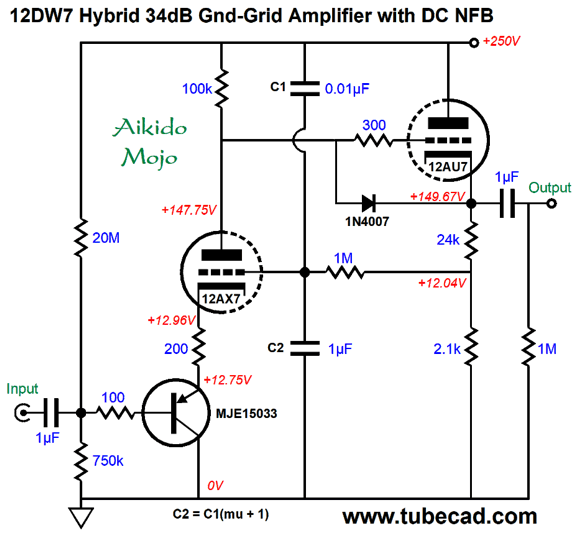
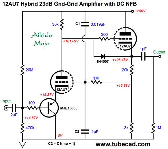
The price we pay for a dramatically improved PSRR is one tiny capacitor (10nF). This added capacitor injects just enough power-supply noise to the grounded-grid amplifier's grid to force a power-supply noise null at the output. The Aikido-mojo capacitor should be 1/(mu + 1) as large as capacitor C2. (Ideally, with a 12AX7 we would use a 0.0099µF capacitor, but 0.01µF is close enough, besides capacitor tolerances would eat up any attempt to arrive at absolute values.) To be frank, this Aikido mojo technique works best with low-mu triode, not high-mu types. Here is the same topology, but with two 12AU7 triodes, whose mu is only 17.
Interestingly enough, the THD is the same for this circuit as it was for the 12AX7-based version with negative feedback. The gain came in at 1:14 (+23dB) and the PSRR was crazy good in SPICE simulations, measuring below -60dB. The only problem is that they do not make a 0.019µF capacitor. The closest readily available values are 18nF and 20nF. With either of these values, the PSRR falls to -37dB. Once again, we run into the relatively poor capacitor tolerances of 5% and 10%, which can easily swamp out our efforts to fine tune. For this reason, it's always better to use 1% resistors (or a potentiometer) to do fine tuning.
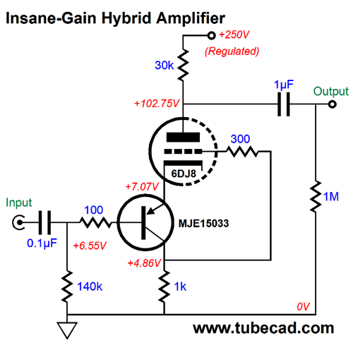
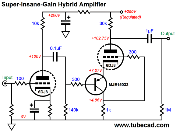
Insane-Gain Hybrid Grounded-Grid Amplifier
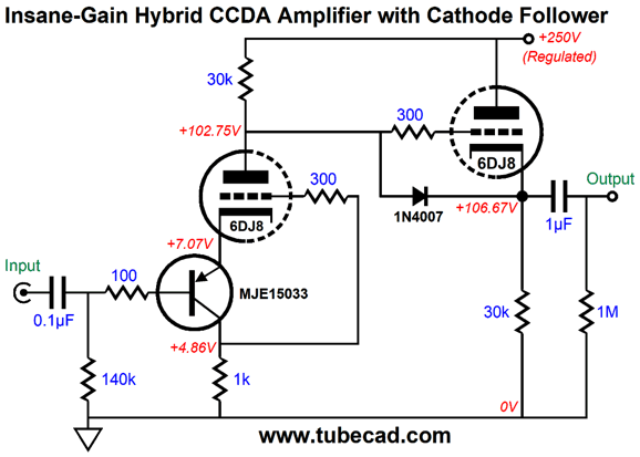
The grid attaches to the 1k collector resistor, which develops an amplified inverted input signal. The resulting gain is 1:250 (+48dB). Effectively, we are employing positive feedback to supercharge the gain. Remember that the 6DJ8's mu tops out at 33, so we are getting 7.5 times more gain than the triode's amplification factor. However, in DC terms, the grid's DC connection to the collector circuit also defines a positive feedback loop, which is scary. Perhaps the best workaround would be to add an internal coupling capacitor, to retain the AC but not the DC positive feedback. Before making the move in this new direction, let's look at adding a cathode follower output stage to buffer the high gain.
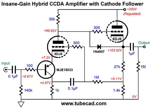
The cathode follower offers an output impedance of about 100 ohms. Since the plate resistor and the cathode follower's cathode resistor share the same value, and since the cathode follower operates in voltage phase with the first stage, but in current anti-phase, the entire circuit takes on a constant-current-draw aspect. Okay, now we can add the internal coupling capacitor.
The 1M resistor relays the DC information to the input stage's grid, which then auto stabilizes the input triode's current conduction at idle.
For those who are super bold, the following variation creates a super-insane amount of gain.
Something like 70dB of gain should be possible. That's a lot of gain. Who would need that much? The only possible application that I can imagine is a microphone preamp.
Music Recommendation: Antonio Lysy's South America Works on the album
The second album I have listened to and enjoyed immensely is his album, Music From Argentina. Also excellent. Once again, I am prejudiced, perhaps due to reading and loving so much of Jorge Luis Borges works, and my finding Tango music so compelling.
Both albums are available at both Tidal and Amazon Music, with the latter offering South America in high-res. //JRB
User Guides for GlassWare Software
For those of you who still have old computers running Windows XP (32-bit) or any other Windows 32-bit OS, I have setup the download availability of my old old standards: Tube CAD, SE Amp CAD, and Audio Gadgets. The downloads are at the GlassWare-Yahoo store and the price is only $9.95 for each program. http://glass-ware.stores.yahoo.net/adsoffromgla.html So many have asked that I had to do it. WARNING: THESE THREE PROGRAMS WILL NOT RUN UNDER VISTA 64-Bit or WINDOWS 7 & 8 & 10 or any other 64-bit OS. I do plan on remaking all of these programs into 64-bit versions, but it will be a huge ordeal, as programming requires vast chunks of noise-free time, something very rare with children running about. Ideally, I would love to come out with versions that run on iPads and Android-OS tablets.
//JRB
|
|
I know that some readers wish to avoid Patreon, so here is a PayPal button instead. Thanks. John Broskie
John Gives
Special Thanks to the Special 87
I am truly stunned and appreciative of their support. In addition I want to thank the following patrons:
All of your support makes a big difference. I would love to arrive at the point where creating my posts was my top priority of the day, not something that I have to steal time from other obligations to do. The more support I get, the higher up these posts move up in deserving attention. If you have been reading my posts, you know that my lifetime goal is reaching post number one thousand. I have 485 more to go. My second goal was to gather 1,000 patrons. Well, that no longer seems possible to me, so I will shoot for a mighty 100 instead. Thus, I have 13 patrons to go. Help me get there.
Only $12.95 TCJ My-Stock DB
Version 2 Improvements *User definable Download for www.glass-ware.com |
||


| www.tubecad.com Copyright © 1999-2020 GlassWare All Rights Reserved |