| John Broskie's Guide to Tube Circuit Analysis & Design |
|
31 October 2020 Post 518
Happy Halloween! I will sorely miss seeing the children in their costumes this year, but my dogs will be far less troubled due to a silent doorbell. Next year, I will actually carve the above pumpkin.
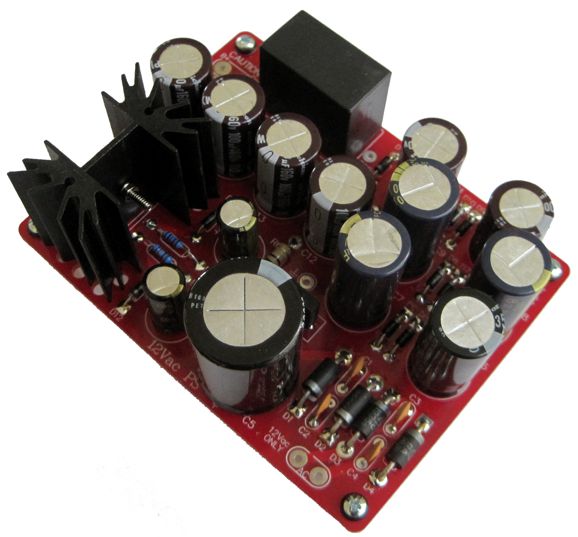
PCB Shipment Arives
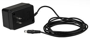
New 12Vac PS I can imagine many uses for this little power supply. For example, it could be used to power a tube buffer circuit in a CD player, which would only require adding a power jack to the player that would connect to a 12VAc wallwart. Speaking of wallwarts, I have used the Jameco 2227604 wallwart many times, always with good results.
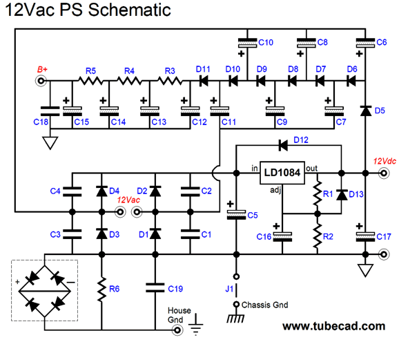
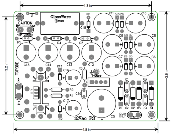
The 12Vac PS receives its power from either an internal or external transformer, usually a 12Vac wallwart, and converts the 12Vac into a regulated 12Vdc for the heaters and high-voltage B+ rail for the tube circuit. If you guessed that 12Vac became 84Vdc, you missed by 1.414 times, which is the square root of 2. A 12Vac sine-wave actually peaks at almost 17Vpk, so the actual DC voltage developed is equal to 8 (12V x 1.414 – Vrect), where Vrect is the total of rectifier’s voltage drops, usually between 0.6 to 0.9 volts per rectifier. In other words, the voltage octupler rectifier circuit creates a raw DC voltage of about 110Vdc to 125Vdc. (As the wallwart's voltage regulation is very poor, the actual DC voltage developed depends on which tubes are used.) In my own build, the raw high-voltage DC voltage was 124Vdc, with 110Vdc of well-filtered DC for the tubes under load.
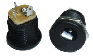
The 12Vac PS PCB holds a three cascaded RC filters to eliminate B+ voltage ripple, R3 through R4 and C12 through C15 . The last RC capacitor, C15, is bypassed by a 10µF polypropylene film capacitor, C18. IMPORTANT: If a power jack is used to connect to the AC voltage, the jack must be fully insulated from the chassis, as the incoming AC voltage is referenced to half the heater voltage.
The 120Vdc voltage is perfect for use with 6DJ8, 12AU7, or ECC99 tubes. The 12Vac transformer should provide at least 2A of current, which equals a VA rating of 24 for use with up to four 12AU7 or 6DJ8 tubes. Ideally, a transformer with a good regulation figure (say the 5% to 10% a good toroidal transformer would offer) would be used; such a fine regulation figure is unlikely to be true of a wallwart transformer, however. Of course, we could use a more powerfully transformer, say a 50VA 12Vac toroid, which would allow for up to 2A @ 12.6Vdc of heater powering. The 12Vac PS PCB also holds an optional house-ground circuit that will engage if the chassis ground differs in voltage from the house ground by more than 1.4V. Jumper J1 allows an easy way to ground the chassis, as the jumper connects the power supply ground to the chassis through the metal standoff. The heater voltage regulator is an LD1084 5A low-dropout regulator. Rectifiers, MUR410G and HER108 are far, far faster than the usual 1N5002 and 1N4007 rectifiers; thus they should not be substituted.
The PCB is 4.8 inches by 3.6 inches, with four mounting holes. The 12Vac PS kit contains all the parts and four standoffs and mounting screws. The 12Vac PS kit is available now at the GlassWare-Yahoo store. +
Sidewinder Hybrid Power Amplifier
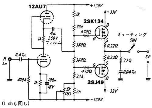
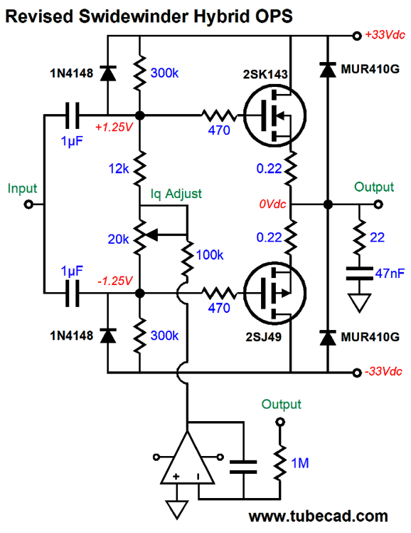
The SRPP input stage uses a 12AU7 tube, which means that its gain is about 1:8 or 18dB. The push-pull MOSFET-based output stage delivers no signal gain, but does provide high-current unity-gain output. The MOSFETs used are the wonderful lateral types (2SK134 & 2SJ49) once made by Toshiba, but now rare. Both the input stage and output stage get bipolar power supplies. This was the aspect that always troubled me, as I could not understand the need for the tube portion of the circuit using the bipolar power supply, as the input stage's output was capacitor coupled, not DC coupled to the output stage. Is this a big deal? It is, as the negative-power-supply noise will be treated as being an equal to the input signal. The bottom triode's cathode sees 100% of the negative rail's ripple. Not a good idea. We want the bottom triode's cathode to be ground-referenced, not referenced to the negative-power-supply rail. Here is a quick workaround.
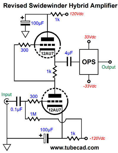
The cathode bypass capacitor now shunts the AC signal at the cathode to ground, not the negative rail. Nonetheless, I don't see why we need the bipolar power supply. If we used a conventional monopolar power supply, we could forgo using the input coupling capacitor. On the other hand, if the input stage were DC coupled to the output stage, then the bipolar power supply would make more sense. Here is one possible variation.
The 6DJ8 replaces the 12AU7 and doubles the input stage gain, without having to use the cathode bypass capacitor. The DC servo eliminates a DC offset voltage at the output. The SRPP affectation has been dropped, as the active-plate-loaded grounded-cathode amplifier offers slightly better PSRR, assuming that the ripple on the positive and negative power-supply rails is equal in magnitude and opposite in phase. Mind you, the DC coupled output is dangerous to your speaker's health, as a jiggled input tube could result in huge output voltage spikes. (I would add an output relay and active speaker-protection circuitry to the amplifier.) A safer variation would retain the internal coupling capacitor.
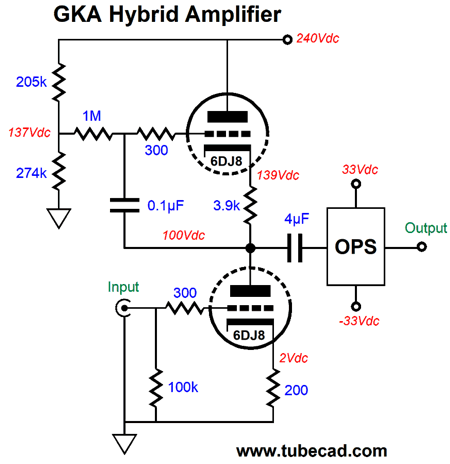
Here we see a grounded-cathode amplifier powered by a 240Vdc monopolar power supply. The top triode approximates a constant-current source, as the 3.9k cathode resistor is amplified by the top triode's mu + 1, and to which we must add the triode's plate resistance. The resulting 135k of impedance allows the bottom 6DJ8 triode to realize more fully its amplification factor as output gain. By the way, the idle current of 10mA implies a DC voltage drop of 39 volts across the 3.9k resistor, but a 1350 volt drop across the 135k impedance. In other words, we could get the same gain by replacing the top triode and its cathode resistor with a single 135k plate resistor and attaching a 1450Vdc B+ voltage to the grounded-cathode amplifier. This circuits PSRR comes in at about -40dB, which could be helped by using an RC filter on the B+ voltage. By the way, I would make a few changes to the output stage.
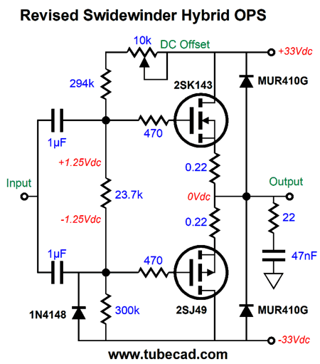
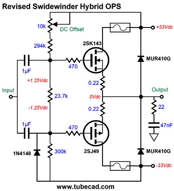
In place of the 4µF coupling capacitor, we see two 1µF coupling capacitors. The two MUR410G "catch" rectifiers are there to protect the output stage from inductive kickbacks from the loudspeaker. The 1N4148 signal diode protects the output stage from big negative swings at turnoff. I seldom show fusing, but I wil do so this time. If one fuse blows, we do not want the ouput to slam into the opposing rail voltage.
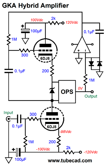
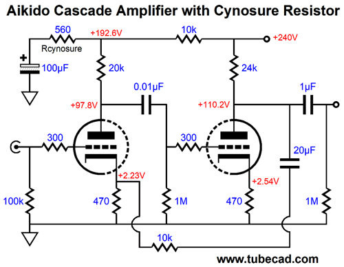
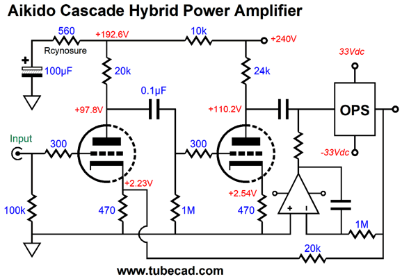
By placing the biasing outside the scope of the fuses, we are safe. Okay, given that we have departed from the SRPP, what other circuits could we use that exploited the two triodes? One possible choice is the Aikido cascade.
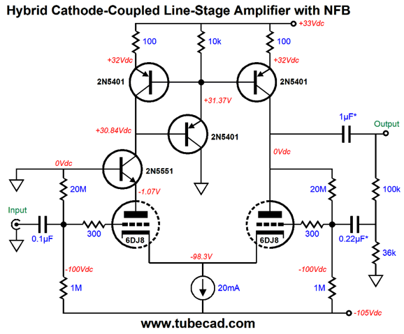
This is a line-stage amplifier that employs a negative feedback loop and offers amazing PSRR. Note that capacitor values throughout were carefully chosen to avoid an unintended bass peak at low frequencies and to ensure that the power-supply noise null extends down to at least 100Hz. The only exception is the output coupling capacitor. Converting it to a frontend for a hybrid power amplifier is easy enough.
The negative feedback loop extends to the output, but it could have stopped at the right triode's plate. The DC servo keeps the output centered at 0V. The open-loop gain is a tad over 1:260. The closed-loop gain is 1:32, easily enough to achieve full output with 1Vpk of input signal. Let's look into the DC servo.
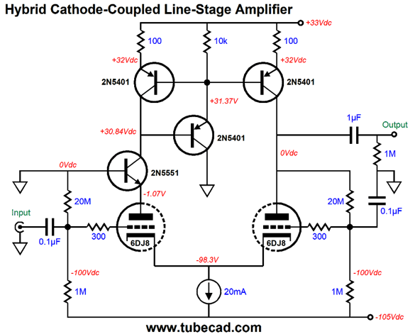
I was about to array many more alternative circuits that held two triodes, when my mind returned to the high-voltage bipolar power supply used in the original circuit. Surely, I thought, there must be some variation that justified its use. My first thought was that if we increase the low-voltage power-supply rail voltages to something like +/-60V, we would have 120 volts for the triodes to operate within. This thought took me to the need for a solid-state current-mirror, rather than use plate resistors. Soon, very elaborate circuits filled my doodle pad, which ran totally counter to the original circuit's simplicity. The topology I liked best made use of a high-voltage negative power-supply rail and the 35V positive rail voltage. Here is a line-stage amplifier version of what I had in mind.
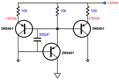
The two 6DJ8 triodes operate near the -105Vdc negative rail, but are referenced to the ground high above. Both triodes share the same idle current ad the same cathode-to-plate voltage. The current mirror is a bit fancier than normal, as the third 2N5401 PNP transistor enhances the mirror's functioning. Indeed, we could get fancier still by adding a small capacitor to the mix.
The 300pF capacitor kicks in when the center transistor begins to fall off at high frequencies. (Too large a capacitor value will, however, undermine performance.) Okay, returning to the circuit, what we have is a fancy cathode-coupled amplifier. The input signal enters the left triode's grid and it is relayed to its cathode, which the right triode then uses as its input signal. The signal is amplified and in phase. The current mirror effectively creates a push-pull output. In other words, the output can swing positive just as well as it can swing negatively. Because the 6DJ8 delivers too much gain for the average line-stage amplifier, we can use a negative feedback loop to reduce the gain and output impedance and distortion.
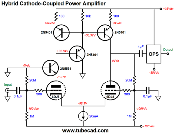
The next step is to use this topology to drive a unity-gain output stage.
(I retained the original circuit's internal 4µF coupling capacitor, but a much lower value can be used.) Given the +/-35Vdc bipolar power supply rail voltages, we could probably get 50W into an 8-ohm load with this amplifier. If we wish to live dangerously, we could DC couple the input stage to the output stage.
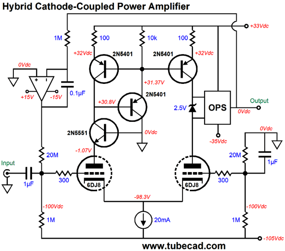
The DC servo works to eliminate any DC offset at the output. An OpAmp with FET input stage should be used. Once again, I would use a relay at the output that would only connect the loudspeaker to the output when the output had settled down after being turned on. On the other hand, if the amplifier were used in a bi-ampped setup, where it drove the midrange and tweeter, both of which would see DC-blocking crossover capacitors, a relay probably could be left out. Note that no negative feedback loop, neither a local nor global, was used. If we wished to use one, I would flip the power supply. In other words, I would use a 140Vdc positive rail voltage, rather than the -105Vdc rail.
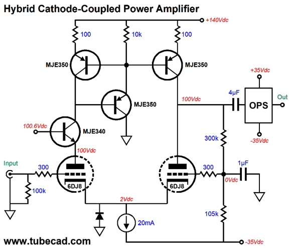
The input stage is now DC-coupled at its input. All the transistors have been replaced by high-voltage types. Internal coupling capacitor and DC servo make the amplifier far safer.
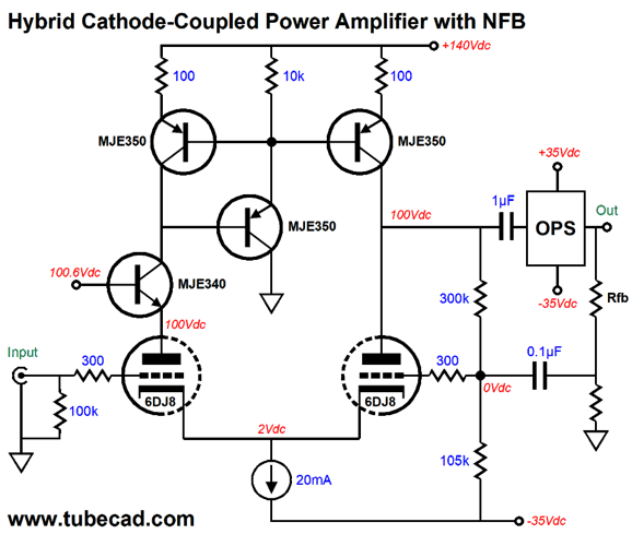
Here we see two negative feedback loops, one DC and one AC. The 300k and 105k resistors provide DC feedback, while the two resistors on the output relay the AC feedback. Note that I removed the protection diode. Why? If plan on getting enough NFB with the 6DJ8, the input signal must be a relatively high amplitude, say +/-10Vpk, which means the cathodes will also swing +/-10Vpk. On the other hand, we could use two 12V zeners in series and opposition in place of the singe diode.
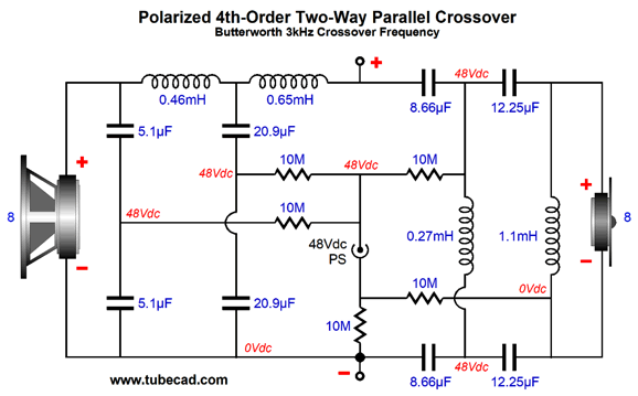
Polarized 4th-Order Crossover
In order to polarize the capacitors, we must use twice as many, at twice the capacitance.
Yes, it does look complicated. Note that the negative voltage must be applied through two 10M resistors, as we need to provide a path to ground for the tweeter-side of the capacitors.
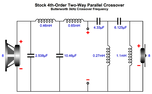
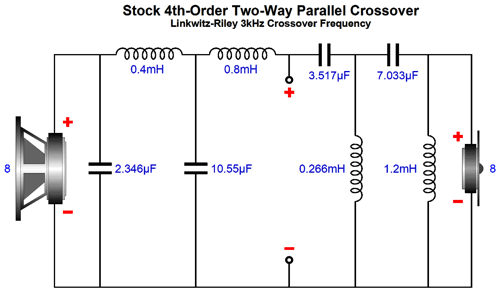
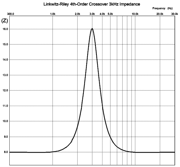
Linkwitz-Riley 4th Order Crossover
Note that the tweeter's phasing is the same as the woofer's. Here is the SPICE generated impedance plot for the crossover shown above.
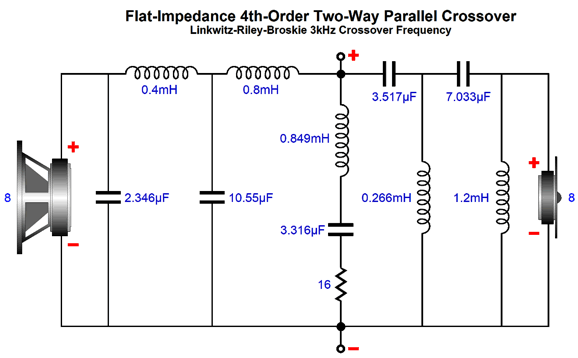
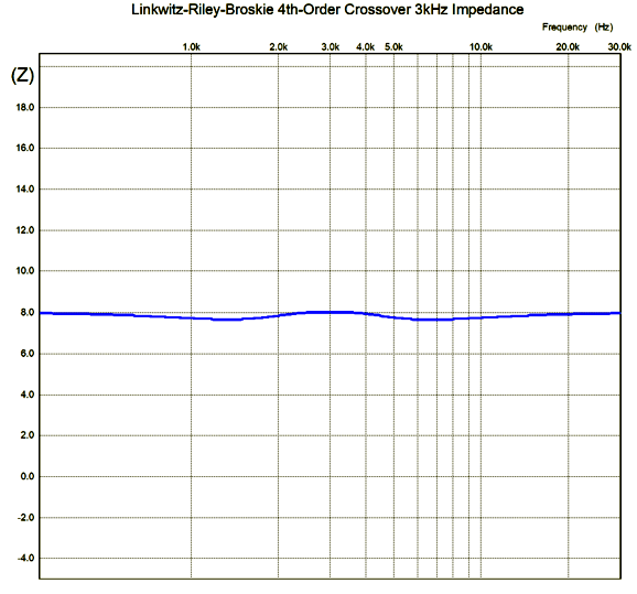
My workaround is to add an impedance-flattening network, thereby creating a Linkwitz-Riley-Broskie (LRB) crossover.
The flattening network's impedance is infinite at DC and at infinitely high frequencies, but dips down to 16 ohms at the crossover frequency, resulting in a far flatter impedance plot for the LRB crossover, as seen below.
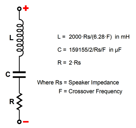
The LRB crossover will make your tube-based amplifier much happier, as such amplifiers assume a flat load impedance. Of course, the speaker's impedance can be and should be made flatter by adding a Zobel network across the woofer. The math behind this network for the 4th-order LRB crossover differs from the 2nd-order impedance flattener that I have shown before for the 2nd-order LR crossover.
The 6.28 in the inductor's formula is a truncation of 6.2831853, for those who seek precision; in other words, 2 pi.
Music Recommendation: Camille Thomas
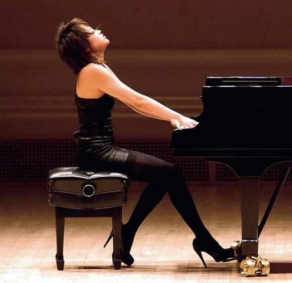
What Ms. Thomas brings is youthful exuberance, lots of it. I discovered her when I went searching for a performance of the contemporary cello concerto, Never Give Up, composed in response to terrorist attacks in Europe and Istanbul by the Turkish composer, Fazil Say. That search led me to the young Belgian cellist’s two albums on the German Deutsche Grammophon label. Let me be frank here: I have been apprehensive about the now three-decade-long strategy that most classical labels seem to have been pushing, namely finding babe classical performers. While physical beauty is certainly welcomed and appreciated, physical beauty must never become a necessary attribute for a classical musician. (Opera is different, as its singers must also be actors and we do look at them in performance.) I listen to classical music, I don't look at it. I wish that Liszt had not started the standard of turning the pianist and piano so that the audience could admire his fine profile, as today we must divide our attention between Yuja Wang's amazing virtuosity and stunning legs. Her heels are as sharp as her Beethoven.
In other words, I was a tad irked to see on the Voice of Hope cover Ms. Thomas in the semi-transparent dress , in spite of her attractive legs and feet. (Male cellists are never required to pose in speedos for their album covers—Thank God!)
Well, after hearing both albums, I am no loger irked. Neither album is likely to be added to the list of the best classical albums of this century. Nonetheless, both are immensely enjoyable to hear. I look forward to hearing much more (and seeing less of her lovely legs) from her. //JRB
User Guides for GlassWare Software
For those of you who still have old computers running Windows XP (32-bit) or any other Windows 32-bit OS, I have setup the download availability of my old old standards: Tube CAD, SE Amp CAD, and Audio Gadgets. The downloads are at the GlassWare-Yahoo store and the price is only $9.95 for each program. http://glass-ware.stores.yahoo.net/adsoffromgla.html So many have asked that I had to do it. WARNING: THESE THREE PROGRAMS WILL NOT RUN UNDER VISTA 64-Bit or WINDOWS 7 & 8 & 10 or any other 64-bit OS. I do plan on remaking all of these programs into 64-bit versions, but it will be a huge ordeal, as programming requires vast chunks of noise-free time, something very rare with children running about. Ideally, I would love to come out with versions that run on iPads and Android-OS tablets.
//JRB
|
|
I know that some readers wish to avoid Patreon, so here is a PayPal button instead. Thanks. John Broskie
John Gives
Special Thanks to the Special 89
I am truly stunned and appreciative of their support. In addition I want to thank the following patrons:
All of your support makes a big difference. I would love to arrive at the point where creating my posts was my top priority of the day, not something that I have to steal time from other obligations to do. The more support I get, the higher up these posts move up in deserving attention. If you have been reading my posts, you know that my lifetime goal is reaching post number one thousand. I have 482 more to go. My second goal was to gather 1,000 patrons. Well, that no longer seems possible to me, so I will shoot for a mighty 100 instead. Thus, I have 11 patrons to go. Help me get there.
Only $12.95 TCJ My-Stock DB
Version 2 Improvements *User definable Download for www.glass-ware.com |
||


| www.tubecad.com Copyright © 1999-2020 GlassWare All Rights Reserved |