| John Broskie's Guide to Tube Circuit Analysis & Design |
|
11 November 2020 Post 519 New PS-24
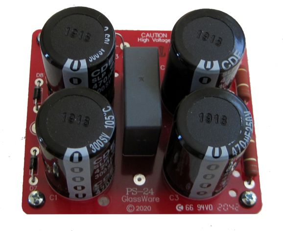
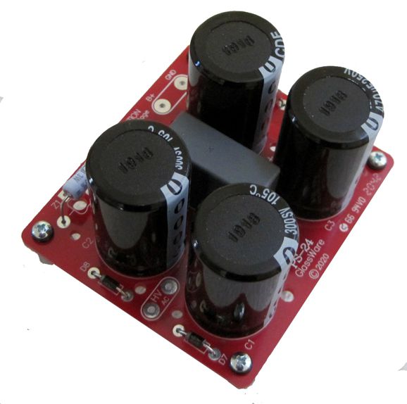
PS-24 High-Voltage Power Supply
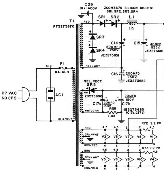
And here is the Heathkit W-6M power supply.
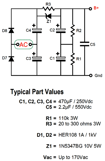
The new PS-24 high-voltage power supply uses a full-wave voltage doubler rectifier configuration and an RC filter to provide suitable B+ voltage for a tube power amplifier.
The PCB requires a 100Vac to 170Vac secondary winding to power the power supply. The RC filter consists of a 20 to 300 ohm series resistor (R3) and two 470µF capacitors (C3 & C4) in series, effectively making a 235µF/500V capacitor. Zener Z1 is optional; it works much like a swinging choke in a power supply, as at idle the RC filter scrubs away ripple, but at full output the zener engages, limiting the voltage drop across the RC filter's resistor to 12V; thus, the output tubes do not see their B+ voltage collapse. When the zener engages, the RC filter falls out of the circuit and all the rail reservoir capacitors are in parallel with each other, bringing each rail's capacitance up to 470µF at 500V. At idle, we want to drop about 6V to 8V across the RC resistor. To find R3's value, divide 7 by the idle current draw. For example, if the total amplifier current draw at idle is 200mA, we get 35 ohms, with either 33 or 36 ohms being close enough. On the other hand, we could leave resistor R3 off the PCB and attach the leads from an external choke instead. (I would leave the zener in place as long as the choke's DCR isn't too high or use a 1N4007 rectifier to catch inductive voltage spikes at turn-on and turn-off.) A secondary voltage of 170Vac will result in a B+ voltage of 475Vdc before the RC filter, the result of multiplying the AC voltage by twice the square-root of 2 (2.83). Of course, if we are doubling the voltage, we are also halving the potential current delivery by 2; then we must include the current-reduction factor due to rectification, so the reduction becomes 3.6. For example, if the current rating of the secondary is 300mA, we divide 300mA by 3.6 and get 83mA. If you do all the math you see that we get same final power-supply efficiency of a conventional full-wave bridge rectifier circuit, i.e. about 78%. For example, a 100VA transformer will yield about 78W of DC power, but 100W of AC power with a resistive load.
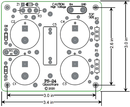
The 470µF/250V capacitors are rated for peaks of 300V, which is useful in a tube power amplifier, as the B+ voltage will drop after the tubes heat up, but at start-up, the voltage will prove much higher. Here are the PCB dimensions:
The PS-24 kit is available at the GlassWare-Yahoo store.
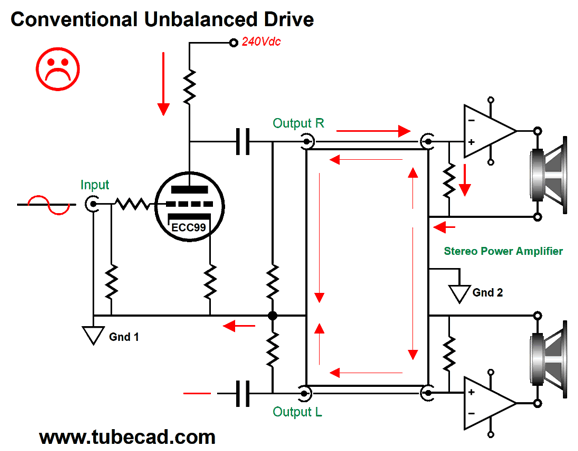
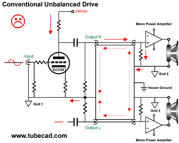
Quasi-Balanced Unbalanced Drive During our talk, he told me that he had recently performed some experiments with monoblock power amplifiers. He had frequently noted that they produced a better stereo image than the exact equivalent stereo power amplifier, but he could not explain why. His experiment was to bridge both amplifier grounds with a long length of wire; the image suffered. He broke the connection; the image was restored. Why? He had no answer, but wished that he could listen to an entirely separate stereo system that held in each channel a mono phono stage, mono line-stage amplifier, and monoblock power amplifier. I performed my own sonic tests, which supported his observations. Why would bridging the signal grounds diminish the sound? In contrast to most, my natural viewpoint is to think primarily in terms of current, then voltage. Viewed from the current perspective, I noted an obvious flaw in the conventional stereo setup that held stereo CD players, stereo phono stages, stereo line-stage amplifiers, and stereo power amplifiers—namely, you always get two return current paths between devices, not one.
We read the ads for $10,000 interconnects, which proclaim the amazing geometry and construction of the cable, often accompanied by artwork showing the directions of the signal flow through the cable and then back through the cable. But when you attach your DAC to your stereo line-stage amplifier, all the signal current in the right channel runs through the right channel's interconnect's hot center wire, but returns through both channels' ground wires and shields.
The right channel's signal current doesn't know that it should stick to the right interconnect; instead, it travels down the path of least resistance, which both channels ground wires and shield create, as two equal resistances in parallel will offer half the resistance of one of the resistances. In contrast, a balanced system will confine the right channel's signal currents to the right channel's interconnect, as a voltage null is created in the driven audio component, so there's no excess current to flow through the left channel's interconnect. So, should we only use monoblock power amplifiers? It depends: the answer most audiophiles hate most. What makes you think that your two mono amplifiers are linked by just the line-stage amplifier? For example, most big power amplifiers use three-prong power plugs, with the third prong attaching to the house ground—and to the signal ground. In other words, you could have each power amplifier attaching to wall sockets on opposing walls and having the third prong and the fifty feet of wall wiring connect both amplifier grounds. Just because you cannot see the connection does not mean it's not there.
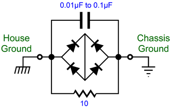
Some take the unsafe workaround of using cheater sockets to break the connection to the house ground; a bad and dangerous idea. The better workaround is to use a house-ground circuit, which uses a 10-ohm resistor shunted by a small capacitor and forward and reverse biased rectifiers to break the direct connection to the house, yet still provide safety, as the diodes will become forward bias and conduct, if the chassis ground differs in voltage from the house ground by more than 1.4V.
Compared to the low resistance presented by the interconnect's ground wire (and shield) the 10-ohm resistor's relatively huge resistance will drastically diminish the signal current from taking that path back to the line-stage amplifier. Not only power amplifiers regularly connect their signal ground to the house ground, but many tube-based line-stage amplifiers.
I covered all this before in several posts, the best effort probably being in post 356. In that post, I showed my electronic workaround, both solid-state and tube-based. I have yet to try these circuits. Why not? Life. (I have never felt the need to kill time; on the contrary, I could use an extra 8 hours a day.) Here is the SPICE circuit I used to evaluate the conventional setup.
And the SPICE-generated results.
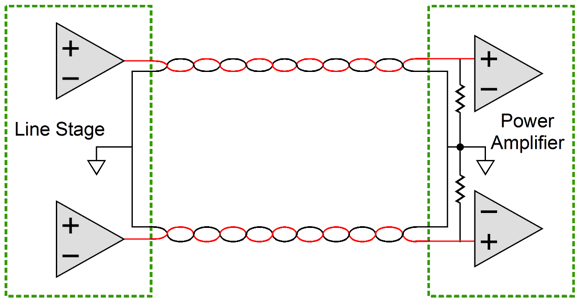
The graph shows the current relationships, with 1Vpk of output signal. Just as we expected, the return current flows through the two ground paths provided, each getting exactly half the current flow. Let's compare the situation with true-balanced drive.
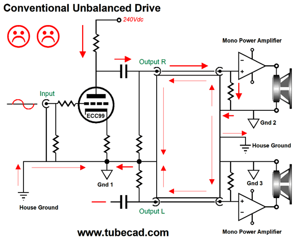
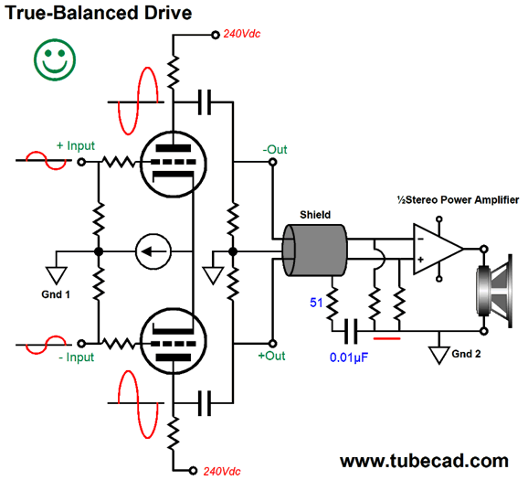
Note how the two phases cancel at ground-2 in the power amplifier. Since the anti-phase signal compels the current flow through the inverting output, no current is left to flow through the other channel. Moreover, note that ground-1 and ground-2 are not directly tied together; instead, each channel uses the 51-ohm resistor and 0.01µF capacitor to prevent the shield from acting as if it were an antenna. This brings up the dreaded Pin-One problem.
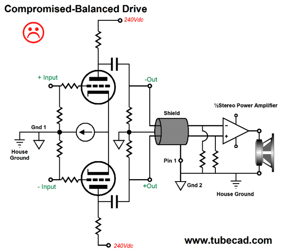
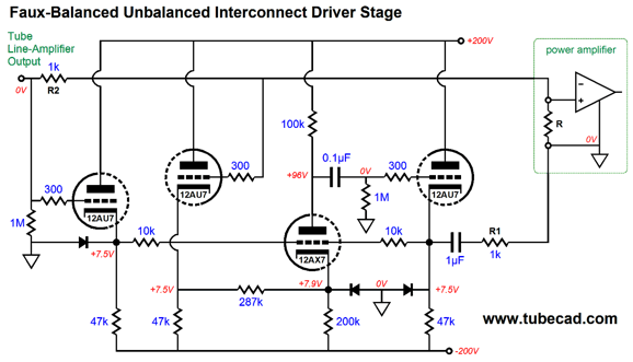
Two big problems mess the beauty of balanced operation here: the first is that pin-1 is used to connect ground-1 to ground-2; the second is that the line-stage amplifier and power amplifier connect to the house ground. In other words, we lost much of the balanced magic. So, how do we get balanced performance with unbalanced input signals and RCA plugs and jacks? Here was one of my solutions from post 356.
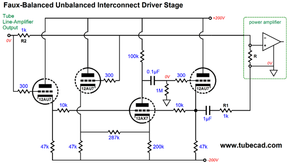
And here is its vacuum-state brother.
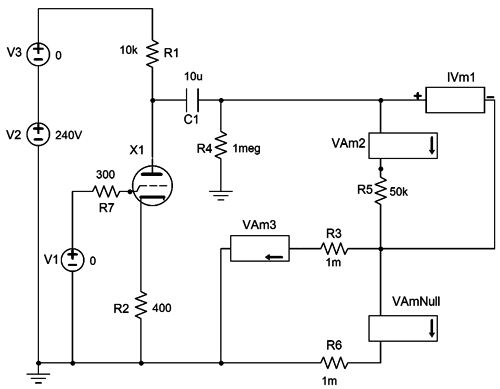
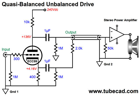
Well, I was thinking that there must be a quicker way to test the balanced-null, the quasi-balanced unbalanced drive concept. I have been pondering what would be the simplest circuit possible? Then it came to me: the grounded-cathode amplifier with an unbypassed cathode resistor.
Note that the plate and cathode resistors share the same current path, which means that the cathode resistor will develop an output signal equal to Rk/Ra as big as the plate puts out. For example, with the 10k plate resistor and 400-ohm cathode resistors, the cathode will swing in voltage by 10k/400 as much as the plate does; in this example, 1/25th as much. Thus, if the peak plate output is 2.5V, the cathode output will be 0.1Vpk. In addition, the cathode output is in phase with the input signal, while the plate's output is inverted. The power amplifier's input resistance is 50k, so we divide 50k by 25 and get 2k as the null-resistor value. If the math proves right, the two output signals will meet at the power amplifier's ground (Gnd 2) and cancel.
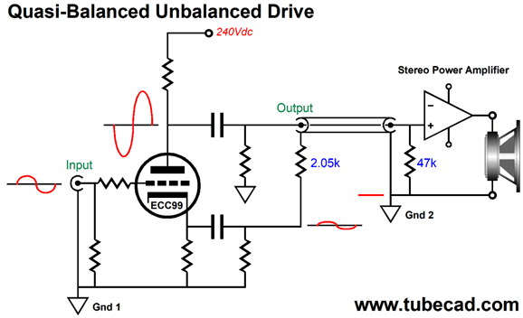
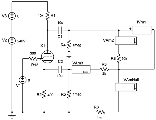
Because the signal level at the power amplifier's ground is zero, no current can flow through the stereo power amplifier's ground to the other channel's RCA jack and flow back to the line-stage amplifier. Here is the SPICE circuit to evaluate the forced-balance concept.
The following is the SPICE-generated graph.
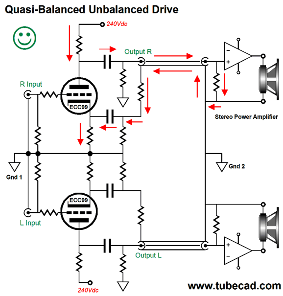
The graph shows the current relationships, with a 1Vpk of output signal from the plate and -0.25Vpk from the cathode. Note that almost all the return current flows through the 2k resistor and tiny trickle flows through the other channel's grounded interconnect, represented here by the 1 milliohm resistance. Stop and think about this: the 2k resistor presents 2,000,000 times more resistance than the 1-milliohm interconnect ground wire and shiel, yet the cureent flows through the 2k resistor rather than the other channel's interconnect. Because of small phase shifts between the plate signal and the cathode signal, however, the tiny discrepancy occurs.
The current only flows through the right channel's interconnect. This setup will also work with two monoblock power amplifiers that attach to the house ground. One possible complication is that many power amplifiers, especially solid-state amplifiers, hold convoluted input networks, whereas the assumption here has been that only a 50k input resistor was used. In contrast the circuits shown in post 356, work even with a complicated input circuits. By the way, the two output coupling capacitors are effectively in series, so their values effectively halves. I used the 10µF coupling capacitors in the SPICE simulations to avoid phase shifts. One important requirement is that the B+ voltage must be noise free, preferably regulated, as the amount of leaked ripple DOES NOT match the same ratio as the signal outputs from plate and cathode. What about the signal source feeding the line-stage amplifier? The best workaround to avoid the two-current-path problem is to use an input signal transformer, as the input signal current will be confined to the transformer's primary as long as the primary isn't grounded. In addition, the input transformer allows for easy phase reversals and breaks ground-loops. (A godsend when trying to hook up a cable-TV audio feed.) Alternatively, we could try the differential-input setup, wherein the RCA jack grounds are NOT grounded; instead, they each terminate into a 10-ohm resistor.
The return current is given the choice of fighting the 10 ohms of resistance to get to the other channel's interconnect ground wire and shield or the 1-milliohm resistance of the driven interconnect.
Crisscross Bastode Input Stage
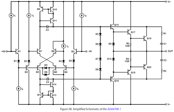
What really caught my attention was its simplified schematic.
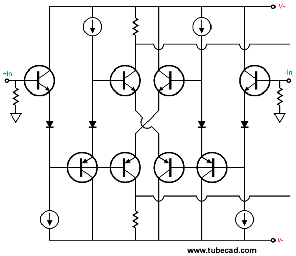
Two modified diamond input stages drives two crisscrossed bastode cascodes. Here is a further simplified schematic.
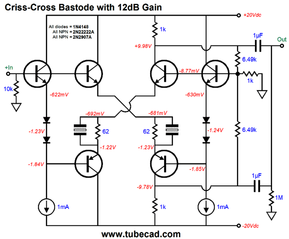
The diodes perform needed voltage shifts, so both the inverting and the non-inverting inputs are at the same voltage level. Well, this design provoked a profound sense of déjà vu in me, as I remembered designing a similar circuit a few years ago. I went hunting, which is never easy, as I have drawn thousands and thousands of schematics. Here is what I had found: a solid-state line-stage amplifier that offers 12dB of gain and a tube-like distortion harmonic structure.
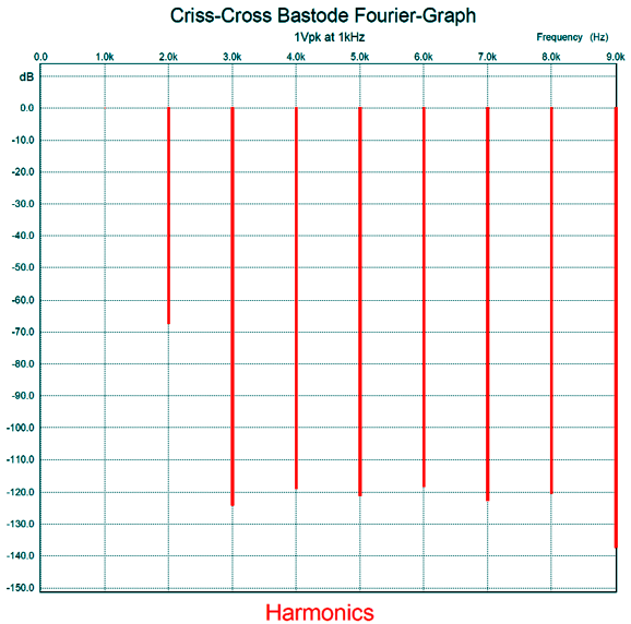
The two 62-ohm emitter resistors set the idle current flow through the two bastode stages. The non-polarized electrolytic capacitors shunt the resistors, which preserves the bastode gain. The two 6.49k negative feedback resistors are effectively in parallel, combining to 3.245 ohms, which with the 1k resistor sets the gain to 1:4 or +12dB. The distortion's harmonic structure is super interesting, as it is primarily 2nd harmonic and little else. This circuit might prove to be that Holy Grail of solid-state circuits that actually do sound like tubes.
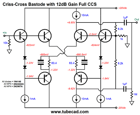
Not bad. In fact, really nice. Note the suppressed 3rd harmonic. I wondered if replacing the 1k resistors with constant-current sources would improve the circuit's performance.
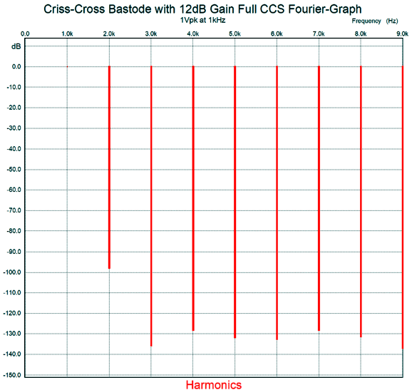
Yes, 10mA is a lot of current, if that was what you were thinking. A line-stage amplifier doesn't have to swing much output voltage, but it might have to drive long lengths of high-capacitance interconnect, which does requires current. Here is the SPICE-generated Fourier graph.
The next thought I had was, how well would actual solid-state constant-current sources perform compared to the SPICE constant-current sources, the type made of transistors and resistors?
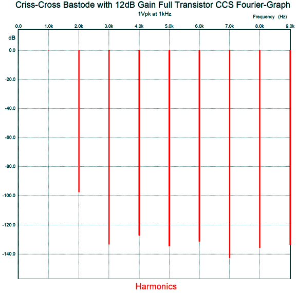
Note how the constant-current sources at the bottom all share the same voltage reference. Here is what SPICE showed.
Surprisingly good. Note how low the 3rd and 5th and 7th harmonics are. Further hotrodding is certainly possible; for example, we could add two emitter-followers or top-and-bottom current-mirrors, but as it stands, the performance is fine.
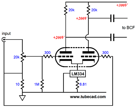
Auto-Bias Hybrid Single-Ended Amplifier
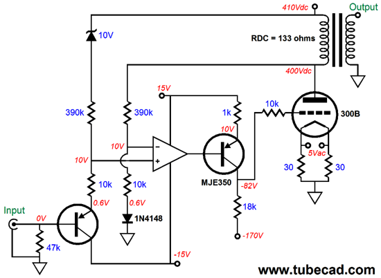
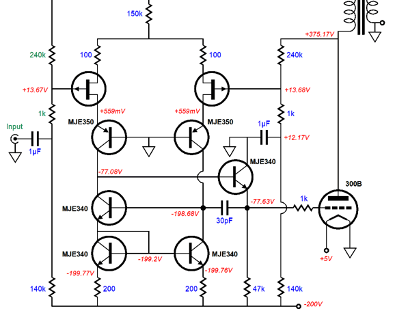
I didn't like having to use the two PNP transistors, which is why I sought a high-voltage OpAmp that wouldn't need any help in swinging huge voltage swings to drive the output tube. Alas, a 300B, due to its low amplification factor, requires such huge grid-voltage swings that a truly high-voltage OpAmp would be needed. Then it hit me, Why not just use discrete solid-state devices? Eight transistors and a few resistors are all that is required.
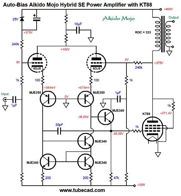
The pair of 2N4403 transistors forms a differential amplifier that is cascoded with the high-voltage MJE350 transistors. The current-mirror at the bottom provides the output signal to drive emitter follower, which in turn drives the 300B grid. Note that the output tube's grid can never be driven positive, as the emitter follower maximum positive voltage swing is to -0.6V, for its collector is grounded. The input signal faces a two-resistor voltage divider made up of the 240k and 1k resistors, so the input signal is attenuated by 240/241 or 0.996. The inverting input receives the negative feedback from its two-resistor voltage divider, also made up of 240k and 1k resistors. This discrete OpAmp, like all OpAmps, strives to maintain the same voltage at both its inverting and its non-inverting inputs. Since the 25V zener drops 25 volts, the negative feedback will auto-bias the output tube so that its idle current produces a 25 volt voltage drop across the output transformer's primary, due to its DCR (direct-current resistance). The Aikido mojo obtains from the input signal being slightly contaminated by 1/241th of the B+ voltage ripple. The negative feedback loop also performs this same AC voltage division, so the discrete OpAmp strives to ensure that the output stage exhibits a PSRR of zero, as all the B+ voltage ripple will appear at the output tube's plate. Isn't this bad? No, just the opposite. Here is a schematic from post 314 that makes this point.
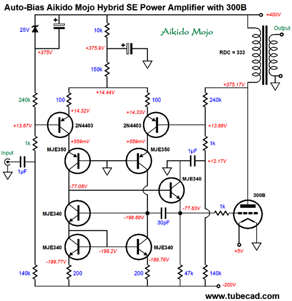
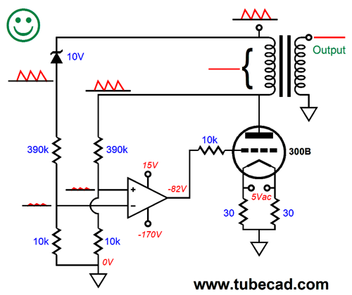
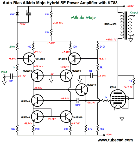
If the output transformer primary sees the exact same amount of noise at both its ends, the secondary will have no signal to relay to your loudspeaker. Remember, a transformer is a perfectly differential device. No difference, no signal. Another way of looking at this is to realize that the reason the primary sees the exact same amount of power-supply noise and both its ends is that the output tube is conducting a constant current flow in spite of the power-supply noise at its plate. How is that possible? The OpAmp slightly modulates the 300B's grid voltage so that 300B does not respond to the power-supply noise, thereby denying the primary any variation in the flow of current that it would relay to its secondary. Okay, now imagine that speaker kicks back an inductive pulse. This pulse will be transferred to the primary in a greatly amplified form, due to the winding ratio between primary and secondary, say 20:1. The pulse then goes through the negative feedback loop, and the discrete OpAmp fights to eliminate the pulse. In other words, we get a low output impedance, along with the great PSRR and auto-bias. We do not have to use a 300B as the output tube. Here is a version based on the KT88, which requires far less negative bias, so we can use a negative power-supply rail voltage of only -100V. Remember, tubes are harder to turn off than they are to turn on, so the negative power-supply rail needs to hold more that twice the bias voltage.
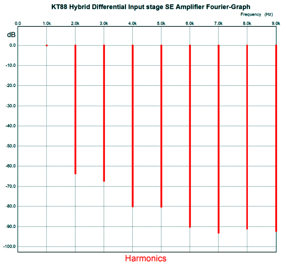
The KT88 is triode-connected. A fun experiment would be to try pure pentode mode instead. Normally, a pentode-based single-ended output stage produces more distortion due to the pentode's high plate impedance, but in this circuit the local negative feedback profoundly reduces its output impedance. Moreover, the distortion is amazingly low, as in better than 0.1% in SPICE simulation at full output, 7.4W. (I would use two KT88 in parallel for almost 15W of output.)
Speaking of negative feedback, what I like about this circuit is that the negative feedback stays entirely on the primary side of the output transformer. Trying to enclose the transformer's secondary within the negative feedback loop is inviting headaches, due to the output transformers many limitations and phase shifts. By the way, we could replace the 2N4403 PNP transistors with P-channel FETs.
The FET's transfer curve is primarily 2nd order; thus distortion harmonics are primarily even-order, in opposition to the odd-order curvature exhibited by bipolar transistors. The huge hassle with FETs, however, is finding matched sets. Okay, why not go triode?
Note the changes in the current mirror, as the triodes are "N-" devices, but the 2N4403 transistors were "P-" devices, which work in opposite current phase. In other words, the triode conducts more when faced with a positive grid voltage; the PNP transistor, less. Ideally, the shared plate resistor would be replaced by a high-voltage constant-current source.
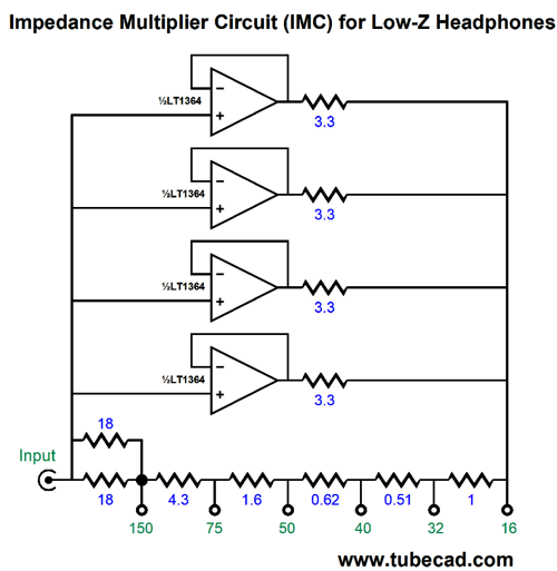
IMC for Headphones
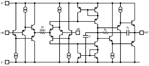
My recommendation was the Texas Instruments TPA6120A2, which is a fine-sounding amplifier and unity-gain stable. The big problem, however, with this dual OpAmp power amplifier is that it is a surface-mount device that uses the PCB copper as a heatsink. Well, just the other day, I returned to Dan's request with a new recommendation: the LT1364, but not just one of them, but two per channel.
The LT1364 is a dual-amplifier OpAmp that can deliver 50mA per amplifier and is unity-gain stable. In addition, it holds eight solder pins and we can plug it into a DIP PCB socket. Like the TPA6120A2, the LT1364 is a current-feedback design and it slews at an astounding 1,000V/microsecond. I quite like the sound from it, very tube like. If we use two LT1364s per channel, a total of four individual amplifiers, we get a maximum output current swing of 200mA, which implies a peak voltage swing of 6.4Vpk into 32-ohm headphones; i.e. ear splitting levels, as 6.4Vpk translates into 640mW into 32 ohms. (I would glue small heatsinks to the tops of each LT1364.)
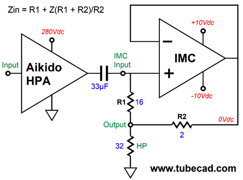
The LT1364 output impedance is 0.7 ohms, so effectively the 3.3-ohm series resistors equal 4 ohms; and effectively the four 4-ohm resistances in parallel combine to 1 ohm. As far as his existing Aikido headphone amplifier is concerned, the load is always 300 ohms. For example, let's say that we are driving 150-ohm headphones. The two 18-ohm resistors in parallel create a 9-ohm resistance; the 4.4 and 1.6 and 0.62 and 0.51 and 1 and 1 ohm resistances add up to 9.03 ohms. Thus, on either side of the 150-ohm tap, there is 9-ohms of resistance, which implies an IMC multiplier ratio of 1:2, so the 150 ohms appears as 300 ohms to the tube-based headphone amplifier. Well, almost. The 9 ohms on the left of the tap must be added, making a total of 309 ohms, certainly good enough for government work. Here is an image from post 484 that shows another example:
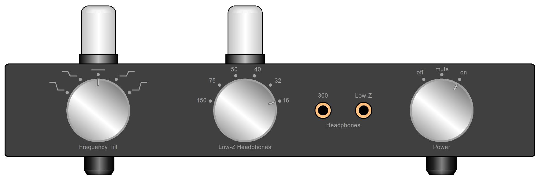
In this example, the load seen by the Aikido headphone amplifier is 304 ohms. Here is the layout I drew for post 484 that shows the front panel with two output jacks, one directly from the Aikido headphone amplifier and one from the IMC.
The switching of the IMC in and out is performed by the 300-ohm headphone jack. If the headphones are plugged into the 300-ohm jack, the IMC is disconnected; if the prong is removed from the jack, the IMC is connected to the Aikido headphone output.
The center rotary knob selects the IMC output tap for both channels. The Tilt Control is something that I deem essential, as different recordings, different generes, different moods—all require a different frequency tilt.
Music Recommendation: Linn Records
Japanese born, but an American resident and percussion virtuoso, Kuniko Kato, has to be heard to be believed, as she creates more satisfying music from percussion instruments than seems possible. A good start would be her album CANTUS.
The Scottish Ensemble is worth knowing, as this string orchestra, which is based in Glasgow, Scotland and led by artistic director and violinist Jonathan Morton, can play beautifully. Speaking of beauty, their album devoted to the late English composer, Sir John Tavener, Tears Of The Angels, drips with beautiful passages.
I discovered Tavener when I noticed as a teenager that The Beatles' recording label, Apple Records, had released an album of Tavener's music, The Whale, in 1970. If you are not acquainted with Tavener's The Protecting Veil, put it on your must-hear list. Steven Isserlis famous best-selling album of the piece is considered the standard (Isserlis had requested the music's composition from Tavener), but Amazon Music also offers Matthew Barley's recent effort (2019) in high-res (24-bit, 96kHz). In addition, the spoken-word tracks by Olwen Fouéré, for example the first track is the poem by Yeats, "He Wishes For The Cloths Of Heaven," are compelling in the extreme. Although this album is not on the Linn label, it is highly recommended.
//JRB
User Guides for GlassWare Software
For those of you who still have old computers running Windows XP (32-bit) or any other Windows 32-bit OS, I have setup the download availability of my old old standards: Tube CAD, SE Amp CAD, and Audio Gadgets. The downloads are at the GlassWare-Yahoo store and the price is only $9.95 for each program. http://glass-ware.stores.yahoo.net/adsoffromgla.html So many have asked that I had to do it. WARNING: THESE THREE PROGRAMS WILL NOT RUN UNDER VISTA 64-Bit or WINDOWS 7 & 8 & 10 or any other 64-bit OS. I do plan on remaking all of these programs into 64-bit versions, but it will be a huge ordeal, as programming requires vast chunks of noise-free time, something very rare with children running about. Ideally, I would love to come out with versions that run on iPads and Android-OS tablets.
//JRB
|
|
I know that some readers wish to avoid Patreon, so here is a PayPal button instead. Thanks. John Broskie
John Gives
Special Thanks to the Special 90
I am truly stunned and appreciative of their support. In addition I want to thank the following patrons:
All of your support makes a big difference. I would love to arrive at the point where creating my posts was my top priority of the day, not something that I have to steal time from other obligations to do. The more support I get, the higher up these posts move up in deserving attention. If you have been reading my posts, you know that my lifetime goal is reaching post number one thousand. I have 481 more to go. My second goal was to gather 1,000 patrons. Well, that no longer seems possible to me, so I will shoot for a mighty 100 instead. Thus, I have 10 patrons to go. Help me get there.
Only $12.95 TCJ My-Stock DB
Version 2 Improvements *User definable Download for www.glass-ware.com |
||


 for Low-Z Headphones.png)


| www.tubecad.com Copyright © 1999-2020 GlassWare All Rights Reserved |