| John Broskie's Guide to Tube Circuit Analysis & Design |
01 March 2021 Post Number 530
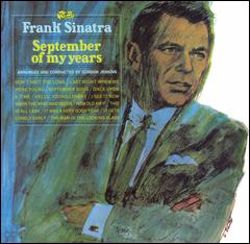
Vinyl The atmosphere, the feel and character, is radically different from digital playback, as playing an LP is similar to watching a live play on stage. Sure, we know the lines Hamlet will utter—but will the actor utter them? Will he forget his lines? Will someone in the audience yell "FIRE!" or just cough loudly? Even ho-hum live plays resemble an acrobat's high-wire act. The potential for disaster hangs over the event, at best postponed but never entirely banished, which prevents us from ignoring the happening. Another interesting aspect to listening to LPs is the archeological attribute of playing 70-year-old records. The record was once new, trapped in its sleeve covered in shrink-wrap. Someone listened to it first. It sang, and then hibernated until awakened for another spin. It rests on the shelf, waiting. I pulled out the mono LP of Sinatra's famous 1965 album, The September of My Years.
As the 56-year-old LP played, I felt as if I had traveled back in time, when cigarette smoke and a tall glass of whiskey would accompany Frank's seemingly singing in our house. An amazingly intimate experience. In contrast, digital music files have no touchable physical reality, especially when they stream into our houses. We can play them repeatedly, without fearing ever physically wearing them out. No ticks, pops, or scratches will befoul our listening, but just as missing as the cigarette smoke in the room and the whiskey in the tall glass will be some magic.
More Infinite-Z Amplifiers
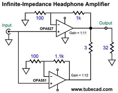
One thought I had was that we are not limited to tube-based and solid-state amplifiers, as we could use either two tube-based amplifiers or two solid-state amplifiers. Let's look at a small example: an OpAmp-based headphone amplifier, but this time the higher gain amplifier is on the bottom.
The OPA637 is a much beloved and expensive OpAmp. Its maximum output current is only 45mA, however, which is insufficient for many low-impedance, high-end headphones. The OPA551, in contrast, can deliver up to 200mA, but not the OPA637's high slew rate or its sweet sound. Using both OpAmps in the infinite-Z configuration allows the OPA637 to control the signal sent to the headphones, without having to deliver the required heavy current flow. In other words, the OPA637 need only supply sufficient current to repair the output cascading from the OPA551. Another possible mate for the OPA637 is the LM1875, a small IC power amplifier in a five-pin TO-220 package.
Infinite-Z Hybrid Headphone Amplifiers
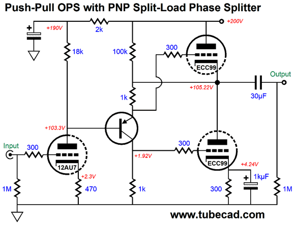
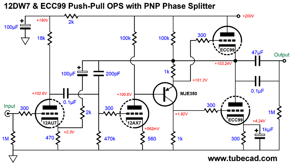
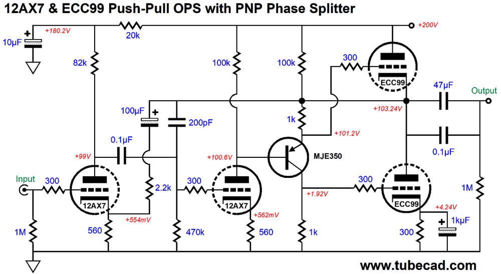
The ECC99 triodes are configured in a push-pull output stage that uses a PNP transistor (MJE350) for the phase splitter. This split-load phase splitter terminates into ground at one end and into the amplifier's output at the other end. The result is that both triodes see a balanced pair of input signals, regardless of the load impedance. The 12AU7 input triode in the grounded-cathode amplifier configuration delivers a gain of about 1:8 (+18dB). On its own, this tube-based headphone amplifier can easily drive 300-ohm headphones. Indeed, its output impedance of about 50 ohms is quite low relative to the 300-ohm headphones. Alas, it is far too high to work with an 8-ohm cascade resistor from the solid-state headphone amplifier. One workaround would be to replace the 12AU7 with a 12AX7 and apply a negative feedback loop.
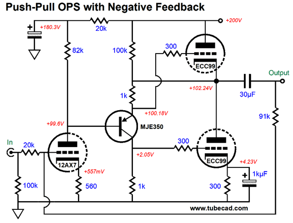
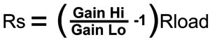
If we set its gain to only 1:4 (+12dB), we can get the output impedance down to about 8 ohms, which gets us much closer to something usable. In fact, it might prove sufficient, if we altered the gain ratio between the solid-state amplifier and the tube-based amplifier. For example, if the solid-state amplifier's gain were 1:8, the cascade resistor value would equal the headphone's impedance. The formula from post 528 reveals the logic:
What if we add an additional gain stage? The added gain would further power the negative feedback, which would result in even lower output impedance. The tube that immediately came to mind was the 12DW7/ECC832/7247, which I used many times before with good results. This tube holds dissimilar triodes, a 12AX7 and 12AU7 type. When I desired a feedback-free amplifier, I used the 12AU7 as the input triode and the 12AX7 as the split-load phase splitter. Since the MJE350 PNP transistor performs the task of splitting the phase, we can use the 12AX7 as an additional grounded-cathode amplifier.
The 200pF capacitor ensures high-frequency stability, as applies high-frequency negative feedback to the 12AX7 triode's grid. In other words, the 12AX7 triode and transistor and ECC99 triodes all act as a sub-amplifier—at very high frequencies—within a larger amplifier. As I scrutinized this design, I wondered if the 12AX7 and 12AU7 triodes shouldn't swap places. Why? I feared that the MJE350's base was dragging down the 12AX7's plate, whereas the 12AU7's far lower plate resistance and higher idle current would have no problem driving the transistor's base.
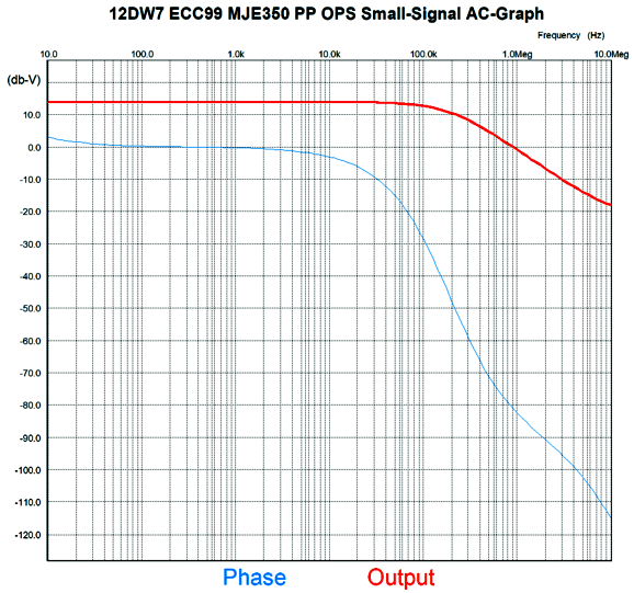
Interestingly enough, in SPICE simulations, both versions worked equally well. But this version did allow for using a smaller-valued decoupling capacitor at the input stage's RC filter. Here are the SPICE-generated graphs for these circuits.
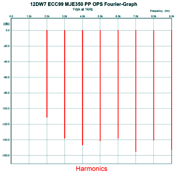
Not bad at all. Here is the Fourier graph for 1Vpk @ 1Khz and 30k load. (Remember, the amplifier should see a near infinite load impedance.)
Note the suppression of the 3rd, 5th, 7th, and 9th harmonics. Nice. Well, since the 12AX7 had no problem driving the MJE350's base, why not use two 12AX7 triodes.
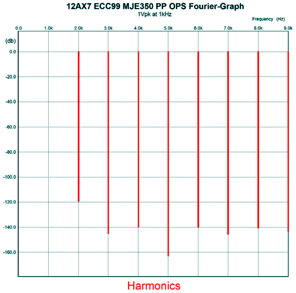
Here is the Fourier graph for this version, with 1Vpk @ 1kHz and 30k load.
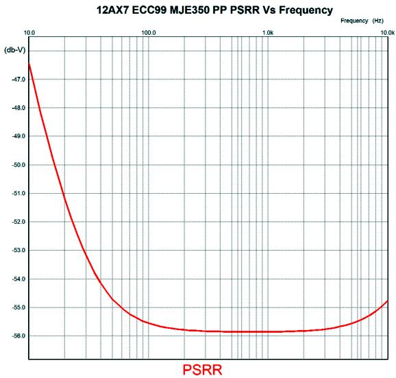
Impressive. The output impedance was 0.2 ohms, plenty low. The PSRR came in at -55.5dB at 100Hz.
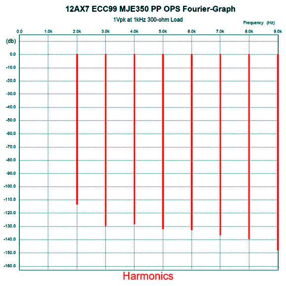
I wondered just how good this tube-based headphone amplifier would be driving a 300-ohm load.
I had to increase the output coupling capacitor value to overcome the Fourier analysis false sensitivity to phase shift, something an actual distortion analyzer is insensitive to. Dang, this is far better than I expected. Even if reality is ten times worse, it is still amazing.
Infinite-Z Amplifier Meets Triadtron
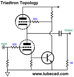
Effectively, this is a single-ended amplifier whose gain equals the triode's amplification factor. The bottom triode draws a nearly constant-current flow, while the top triode's current flow varies wildly when playing music. We can think of this topology as a super-triode configuration, as it meets the three conditions of super-triode operation:
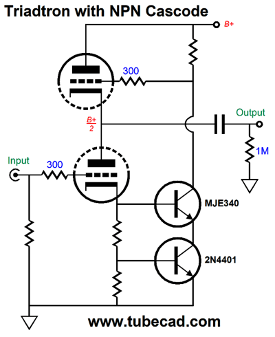
This list appeared in post 375 that nicely explicates super-triode operation. The NPN transistor in the circuit strives to see a fixed emitter-to-base voltage, so its collector voltage varies to achieve the constant base voltage, which can only be obtained if the bottom triode's plate sees negative voltage swings equal to its amplification factor (mu) against the input signal at its grid. Thus, if ±1Vpk of input signal is presented to its grid, its plate must swing ±Vpk∙mu volts in order to establish a constant-current flow through the bottom triode. Since the transistor's emitter-to-base voltage seldom exceeds 0.7V, we might have to use both cathode bias and fixed bias voltage to get the desired idle current through the tubes. One workaround is to cascode the transistor.
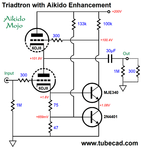
Now, the bottom triode sees the needed cathode voltage and the bottom transistor still sees its desired emitter-to-base voltage. In addition, the top transistor is a high-voltage type, while the bottom transistor is a low-voltage, high-beta transistor. The best of both worlds, in other words. We can even inject some Aikido mojo.
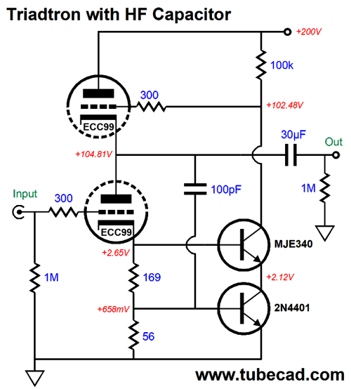
The 133k resistor that bridges the bottom transistor's base to the B+ voltage injects a tiny amount of power-supply noise, which the transistor will work to undo at the output, creating a power-supply-noise null at the output. A further enhancement is the inclusion of a high-frequency negative feedback capacitor.
The added 100pF capacitor prevents ultra-high-frequency instabilities. In SPICE simulation, it did not appear to be needed, but I would use it nonetheless. With the capacitor in place, the high-frequency -3dB rolloff occurred at 240kHz, plenty high. Adding an input stage and applying a negative feedback loop will bring the already low output impedance down to below 1 ohms.
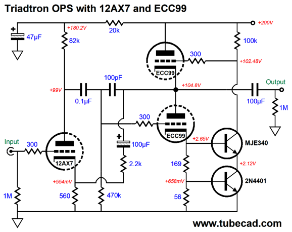
The 12AX7 delivers a gain of about 36, which against the triadtron's gain of 22 (with an ECC99 output tube), equals an open-loop gain of about 800. The closed gain is 1:5. Thus, my guess was an output impedance of 32 milliohms, with the assumption of an output impedance of about 5 ohms from the triadtron output stage. In SPICE simulations, the closed-loop output impedance was 37 milliohms. This is plenty low. The PSRR is insanely low for a tube-based circuit. The high-frequency bandwidth extends to 200kHz. Well, because I can never leave good enough alone, I wondered how an all-tube version would perform. In other words, what if we replace the two transistors with a single 12AX7 triode?
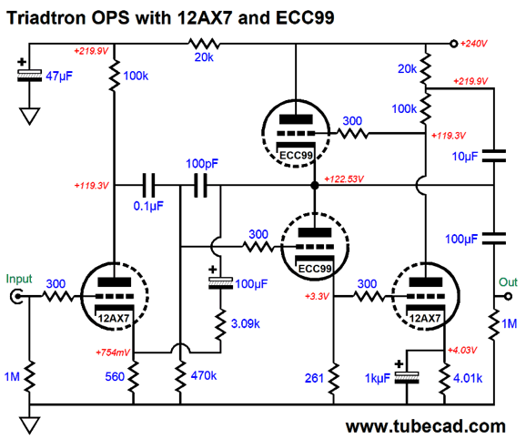
Note that B+ voltage has been upped to 240Vdc. Also note the 10µF capacitor at the output. It bootstraps the 100k plate resistor, making it effectively much higher in value. The added 12AX7 triode enjoys seeing a larger input signal at its grid than the NPN 2N4401 transistor did at is base, as the grid attaches directly to the bottom ECC99 triode's cathode, whereas the transistor faced a two-resistor voltage divider. The result is that the all-tube version sacrifices nothing in performance, relative to the hybrid version. Indeed, its distortion is even lower.
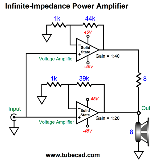
Infinite-Z All-Solid-State Power Amplifier
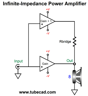
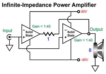
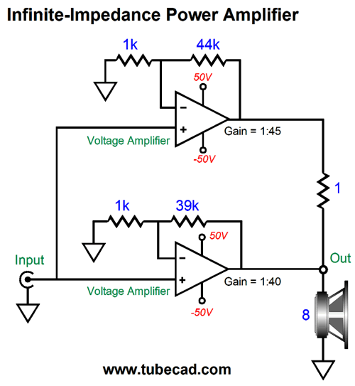
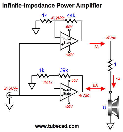
The top amplifier's gain is 45, while the bottom amplifier's gain is 40. Both amplifiers run off the ±50Vdc power-supply rails, and both can swing a maximum of 45Vpk (126.5W) before clipping into 8-ohm loads. Let's apply 1Vdc to the input to see the voltage relationships.
Now, let's look at the voltage relationships with a negative input voltage.
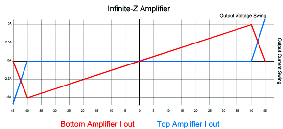
In both examples, the bottom amplifier does not deliver any current into the load. If the top amplifier, however, failed to deliver -9Vdc, then the bottom amplifier would have to deliver 500mA into the speaker. Since the top amplifier draws all the current needed to develop 40V across the 8-ohm load, the bottom amplifier isn't required to deliver any current. Thus, for up to 40Vpk (100W) of output, the bottom amplifier effectively sees an infinite load impedance. But once the output signal begins to exceed 40Vpk, the top amplifier can no longer swing any higher, as its output clips, so the bottom amplifier must begin to deliver serious current. How much is serious? At 45Vpk of output, the bottom amplifier delivers 100% of the current flow, 5.625Apk, while the top amplifier delivers 0A. This makes for an interesting heat dissipation problem. Below 40Vpk, the bottom amplifier just loafs along, but over the last 5 volts of output-voltage swing, it must go from its idle dissipation to a peak of 28.125W.
With the exception of constant-full-power output with a test signal, the top amplifier will dissipate far more heat than the bottom amplifier. This means that we could give the top amplifier's output stage a much bigger heatsink than the bottom amplifier. Alternatively, both amplifiers could share the same heatsink, but the bottom amplifier would get a smaller portion of the heatsink; let's say one third. Heatsinks are a pain, being large, heavy, and expensive. They are a central reason that class-A solid-state power amplifiers are both so rare and so expensive. For example, a 100W class-A amplifier must idle at least at 200W, as the maximum theoretical efficiency is 50%, with reality coming closer to only 40%. In contrast, the infinite-Z example would only idle at 24W and could deliver 126.5W of output. Up to 100W of output, it might sound just as good, if not better, as the 100W class-A amplifier. Why? The top amplifier may never depart from its small window of class-A output-current operation. For example, the optimal idle current for a pair of complementary output transistors with 0.22-ohm emitter resistors is 118mA—at least according to theory. This means that the output stage is capable of swinging up to 236mA of output current before leaving the class-A window. Now, 236mA peak equals only 220mW of output power into an 8-ohm loudspeaker, but that might be all that is required to correct the current flowing from the higher-gain amplifier into the speaker.
Okay, here is a question: What division of output voltage swing between the two amplifiers would yield equal heat dissipation of the two output stages? No easy answer is available without specifying the signal type and the output power. Music differs from a signal generator's steady output, as music constantly varies in frequency and amplitude. Well, ideally it should. Heavily compressed music played at full volume approaches the output of a white-noise signal generator. In general, with soul-pleasing music, a 100W power amplifier played at its maximum output will average only 5W or so.
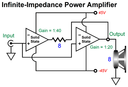
Let's assume a 100W stereo solid-state power amplifier with a gain ratio of 2. In other words, the top amplifier gain equals 1:40, while the bottom amplifier's gain equals 1:20.
Up to 25W of output, the top amplifier delivers all the current flow. Above 25W (20Vpk across 8 ohms), the two amplifiers work in a sliding tandem, as the bottom amplifier begins to deliver some current, then all the current at peak power output. The 8-ohm bridge resistor will get hot, but not crazy hot, as the peak heat occurs at 20Vpk of output voltage swing into the speaker, thereafter it cools. Still, I would use a 50W resistor.
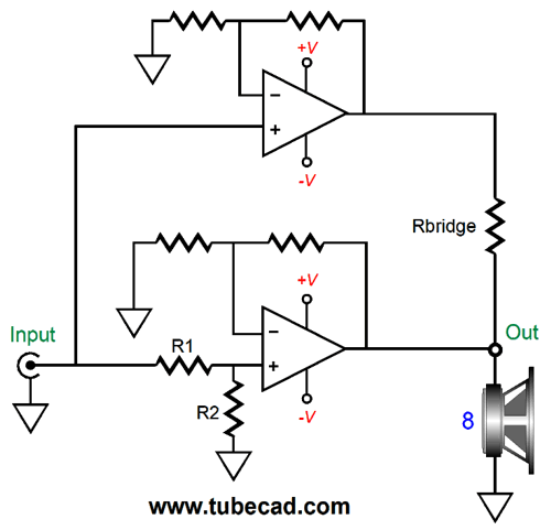
Since the top amplifier offers twice the gain, when the bottom amplifier's output voltage swing hits 20Vpk, the top amplifier will reach its peak output voltage of 40V and clip thereafter. In other words, the top amplifier's output will stick at 40Vdc as the bottom amplifier's output climbs to 40Vpk. At 20Vpk of output voltage, the top amplifier's peak output current flow is 2.5A, but the output transistor sees only a 5V voltage drop, so its instantaneous power dissipation is only 12.5W (plus the nominal idle dissipation). The bottom still is not required to deliver any current, so its output stage dissipation equals its idle dissipation. At 30Vpk of output voltage, the peak output current flow into the 8-ohm speaker is 3.75A, with the top amplifier delivering 1.25A; the bottom amplifier, 2.5A, which against the 15V voltage drop creates an instantaneous power dissipation of 37.5W. The top amplifier's instantaneous power dissipation would be only 6.25W, the result of 1.25A against the 5V voltage drop. (The bipolar power supply rail voltages are ±45Vdc.) No doubt, those with far greater mathematical skill have worked out the optimal gain ratio with sine-wave input signals that would ensure equal heating of heatsinks. But would that mathematically-derived ratio work best with actual music? In other words, is this a case where real-world experimentation is required? I believe it is. For example, we could take an existing 100W stereo solid-state power amplifier and configure it thus:
The two-resistor voltage divider allows us to set the gain ratio between amplifiers. The resistor that bridges the outputs must be varied in value to the match the math required for the load impedance. With this setup, we would measure each amplifier's heatsink temperature with various gain ratios. The signal source would be demanding music, such as punk rock or organ and synthesizer music. Once we establish equal heatsink temperatures, we note the gain ratio and hardwire it into an amplifier. Hell, we could just buy another identical 100W stereo solid-state power amplifier and then add the same two-resistor voltage divider and bridging resistor and listen away. In other words, we have turned a stereo power amplifier into a monoblock amplifier. The 100W power amplifier still only puts out 100W, but we would hope for a very sweet 100W.
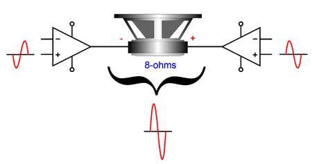
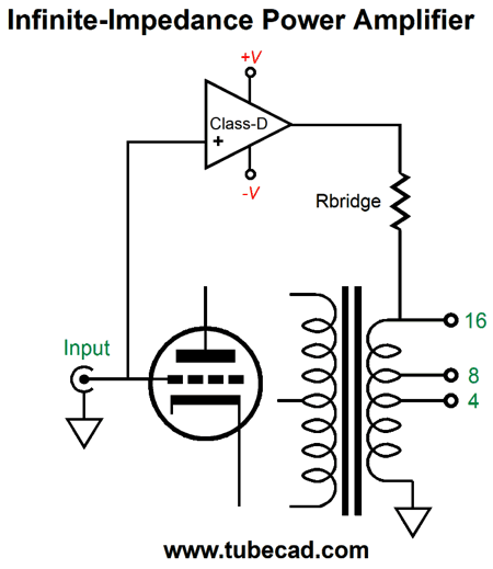
The alternative for the power hungry is to configure the 100W stereo solid-state power amplifier as a bridged mono amplifier. Assuming that the amplifier is robust enough to deliver twice the power output into a 4-ohm loudspeaker than it can into an 8-ohm speaker, the bridged setup would deliver 400W. Impressive. But the 400W would not be as sweet as the 100W into an 8-ohm load, as each amplifier in the bridged configuration effectively drives a 4-ohm load when the speaker impedance is 8 ohms; 2-ohm load, when the speaker impedance is 4 ohms. Of course, we could build an Infinite-Impedance amplifier out of a class-D and class-AB power amplifier, in which case the need for big heatsinks pretty much vanishes. Indeed, we could pair class-D and tube-based class-A amplifiers.
We must work out the needed gain ratio bridge resistor value for a 16-ohm load, and the output transformer would take care of 8-ohm and 4-ohms loads for us. The hard part would be getting a sufficiently low output impedance from the tube-based amplifier.
Music Recommendation: Cuba: The Conversation Continues Afro-Latin music smokes, especially Cuban-Afro-Latin jazz. I have been a big fan for as long as I can remember. Indeed, it doesn't have to be Afro-Latin Jazz, as Afro-Latin music provokes intense toe-tapping, regardless the genre. One of my favorite albums is Putumayo Presents Afro-Latino, an album unknown to most audiophiles—a big mistake.
//JRB
User Guides for GlassWare Software
For those of you who still have old computers running Windows XP (32-bit) or any other Windows 32-bit OS, I have setup the download availability of my old old standards: Tube CAD, SE Amp CAD, and Audio Gadgets. The downloads are at the GlassWare-Yahoo store and the price is only $9.95 for each program. http://glass-ware.stores.yahoo.net/adsoffromgla.html So many have asked that I had to do it. WARNING: THESE THREE PROGRAMS WILL NOT RUN UNDER VISTA 64-Bit or WINDOWS 7, 8, and 10 if the OS is not 32-bit or if the OS is 64-bit. I do plan on remaking all of these programs into 64-bit versions, but it will be a huge ordeal, as programming requires vast chunks of noise-free time, something very rare with children running about. Ideally, I would love to come out with versions that run on iPads and Android-OS tablets.
|
I know that some readers wish to avoid Patreon, so here is a PayPal donate button instead. Thanks. John Broskie
John Gives
Special Thanks to the Special 89
I am truly stunned and appreciative of their support. In addition I want to thank the following patrons:
All of your support makes a big difference. I would love to arrive at the point where creating my posts was my top priority of the day, not something that I have to steal time from other obligations to do. The more support I get, the higher up these posts move up in deserving attention.
If you have been reading my posts, you know that my lifetime goal is reaching post number one thousand. I have 470 more to go. My second goal is to gather 100 patrons. I have 22 patrons to go. Help me get there.
Only $9.95
The Tube CAD Journal's first companion program, TCJ Filter Design lets you design a filter or crossover (passive, OpAmp or tube) without having to check out thick textbooks from the library and without having to breakout the scientific calculator. This program's goal is to provide a quick and easy display not only of the frequency response, but also of the resistor and capacitor values for a passive and active filters and crossovers. TCJ Filter Design is easy to use, but not lightweight, holding over 60 different filter topologies and up to four filter alignments: While the program's main concern is active filters, solid-state and tube, it also does passive filters. In fact, it can be used to calculate passive crossovers for use with speakers by entering 8 ohms as the terminating resistance. Click on the image below to see the full screen capture.
Tube crossovers are a major part of this program; both buffered and un-buffered tube based filters along with mono-polar and bipolar power supply topologies are covered. Available on a CD-ROM and a downloadable version (4 Megabytes). Download or CD ROM
|
|||


| www.tubecad.com Copyright © 1999-2021 GlassWare All Rights Reserved |