11 March 2021 Post Number 531
New Attn-2

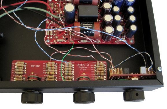
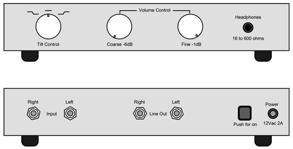
Stepped attenuators deliver decisive clicks and precise attenuation. Sadly, they are never cheap—well, at least the high-quality ones are never cheap, as the sealed switches with hard-gold contacts are expensive in the extreme. Thus, the need to be frugal with the number of switches used. The new Attn-2 uses two rotary switches, one 6-position switch (on the left) for fine decrements of 1dB and one 12-positon switch (on the right) for coarse 6dB decrements, which allows for 0dB to -65dB in 1dB steps for two channels. Here is the schematic for one channel.
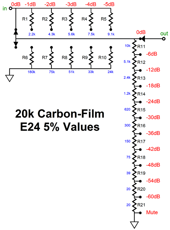
This cleverly designed stepped attenuator exploits both the series-attenuator and the ladder-attenuator stepped-attenuator configurations to yield the best compromise between flexibility, performance, and cost. The Attn-2 attenuator uses two rotary switches and 21 resistors per channel to yield a total of 66 positions of attenuation in -1dB and -6dB decrements. Had the attenuator been entirely of a series design, the attenuator would require a two-deck 66-position rotary switch and 132 resistors; a purely ladder design, a four-deck, 4-pol, 66-position rotary switch and 260 resistors. In contrast, the Attn-2 attenuator, from 0 to -5dB of attenuation, is solely a ladder attenuator, with no more than two resistors in the signal path; thereafter, the attenuator uses both a ladder and series configurations, with never more than 12 resistors in the signal path.
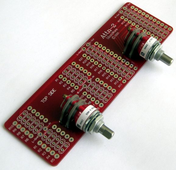
The Attn-2 stepped attenuator is available now at the GlassWare-Yahoo store, both with and without resistors.

A good friend, my son's godfather, has come out of surgery, so I sent him a headphone/line-stage amplifier to help him recover. In addition, it allowed me to try out the new Attn-2 in an actual piece of audio gear.
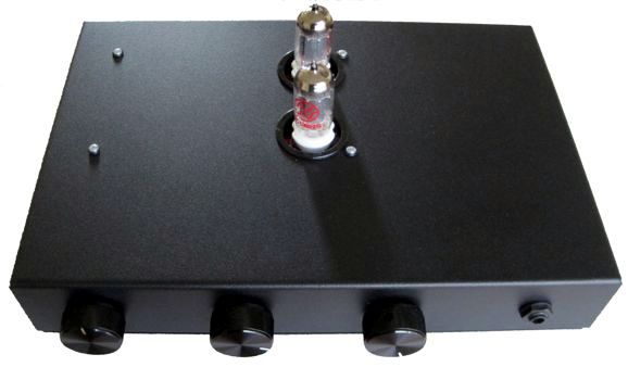
The knob on the left connects to a three-position Tilt Control, which I find absolutely essential to headphone listening. The other two knobs belong to the Attn-2 stepped attenuator. The headphone jack connects to a solid-state unity-gain buffer.
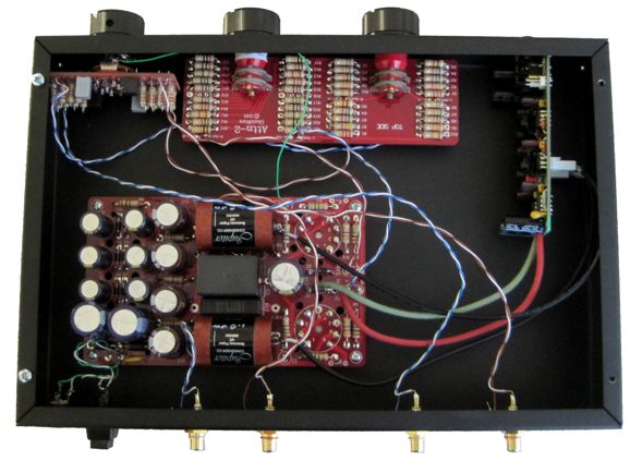
The tube circuit is one of my 12Vac SRPP kits, with all the parts—other than the tube sockets—soldered to the bottom of the PCB.
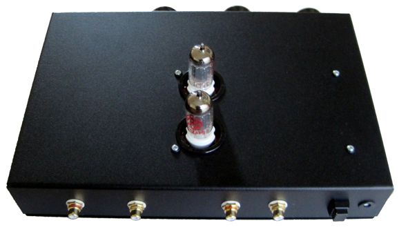
Here we see the Attn-2 attenuator and the Tilt Control. The thick red and green wires deliver the DC voltage to the buffer from the 12Vac SRPP PCB. In other words, the 12Vac SRPP's power supply drives the solid-state unity-gain buffer. The enclosure is just a black-painted steel box and bottom panel from Hammond, 2 by 8 by 12 inches.
Sadly, they no longer sell white rub-on letters for electronics projects, so I had to provide this layout guide.
So, how well did the Attn-2 attenuator work? Extremely well. I always start with the coarse knob and get close, then I adjust the fine knob to zero in on the exact sound level. (Actually, a good practice with headphone listening is to back off on volume from what you think is optimal at first.) As a line-stage amplifier, the sound was far better than I expected, perhaps due to the Jupiter beeswax coupling capacitors I used, but I bet the NOS Amperex 12AU7 tubes should get much of the credit. All in all, it was quick and fun project to put together. Not having to deal with internal power transformers is a relief.

A constant-current source is a current limiter or current regulator that freely allows the flow of current, but only up to a set limit. It is a practicable version of an ideal constant-current source, which would be something like a special battery that delivered a fixed current flow, not a fixed voltage; in other words, it would deliver a steady current flow regardless of the voltage-drop required. For example, an ideal 1mA constant-current source would develop 1kV across a 1M resistor and 1V across a 1k resistor and 1mV across a 1-ohm resistor. In contrast, a battery strives to deliver a fixed DC voltage regardless of the current flow, be it only 1mA or 1A or 1kA.

In the world of SPICE, ideal constant-current sources exist; in reality, they don't. On its own, the famous IC constant-current source, the LM334, neither generates nor creates nor delivers any current—it only serves to limit an existing current flow. In order for an ideal battery (i.e. an ideal voltage source) to deliver a fixed DC voltage no matter how little or how great the current flow, its output impedance must be zero. In order for an ideal constant-current source to deliver a fixed current flow, its output impedance must be infinitely high. Note the inverse symmetry between voltage sources and constant-current sources. Voltage sources present a fixed voltage and allow a changing current flow; constant-current sources yield a static current flow and allow a fluctuating voltage. Both sources are immensely useful in electronics. For example, a triode in a grounded-cathode amplifier topology with a constant-current-source plate load will develop a signal gain equal to its amplification factor (mu), which is found by multiplying the triode's transconductance against its plate resistance.
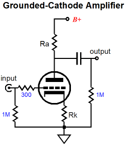
Since the constant-current source presents an infinitely-high impedance, the triode's plate resistance is not shunted by any resistance or impedance, so it can deliver its entire mu as gain. In contrast, a triode with a bypassed cathode resistor and loaded by a plate resistor equal to its plate resistance will deliver a gain equal to mu/2, as the plate resistor is effectively in parallel with the plate resistance, so the effective plate resistance drops to half its nominal value. In a two-triode, long-tailed differential amplifier or in a cathode-coupled amplifier, the constant-current source's infinitely high output impedance makes for the best cathode load, as the two cathodes couple without loss since the infinitely high impedance does not shunt the cathodes to ground.
So far, the constant-current source's infinitely high output impedance has proved a powerful feature. But are there situations where the infinitely high output impedance becomes a liability? I can think of one major example: cathode-biasing a single-ended output tube. Today, many single-ended power amplifiers proudly proclaim an auto-bias feature. Often the advertising copy declares the amplifier is plug-and-play, as the output tube can be replaced without any user adjustment required; in fact, the ad copy loudly details how even different output tubes can be used, such as 6L6 and KT88s and 6550s and KT120s without worrying about setting the idle current. The auto-bias works due to the use of a constant-current source to cathode bias the output tube, with the constant-current source usually being a three-pin voltage regulator configured as a constant-current source shunted by a large-value capacitor.
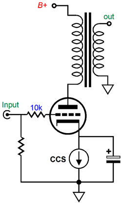
Think about what would happen if the constant-current source were not shunted by a large-value capacitor. What would happen? The output tube would still auto-bias to the desired idle current flow, but no signal would develop at the amplifier's output. A mute amplifier. The grid might see a wildly-varying input signal, but the constant-current source would force an equally wildly-varying, in-phase cathode voltage, so the output tube's current conduction would remain constant. A constant current flow through an output transformer's primary creates no output voltage or output current on its secondary, as the transformer is an intrinsically differential device. No difference, no output. The shunting capacitor hardens the constant-current source so the cathode remains locked to audio AC signals, but can still drift as needed but only at subsonic frequencies, say, below 10Hz. In order for the cathode capacitor to do its job well, the capacitor's capacitance must be high and its own internal effective series resistance (ESR) must be low, as should be its effective series inductance (ESL).
Okay, what if we created a constant-current source that on its own delivered a hard output, i.e. a low output impedance? In other words, what would happen if the constant-current source's output didn't offer an extremely high output impedance? Well, if nothing else, we could use a far smaller-in-value and far higher-in-quality cathode shunt capacitor, say, a 1µF polypropylene capacitor instead of a 100µF electrolytic capacitor. The next question is: How do we create a hard constant-current source? One possible circuit is to modify the existing three-pin, voltage-regulator constant-current source. First, let's look into the positive regulator's internal circuit.
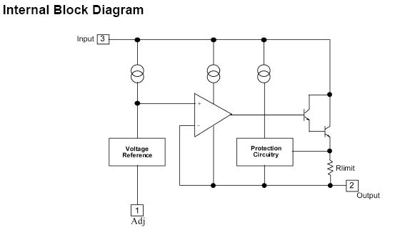
We see that the regulator holds three important sub-devices: a 1.25V voltage reference, an OpAmp, and a Darlington NPN transistor arrangement made up of two NPN transistors in cascade—all of which can be put to use in a constant-current source.
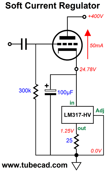
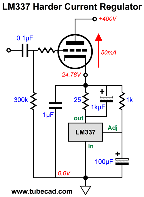
Note that the LM317-HV is used, whose maximum input voltage is 57V as opposed to the normal LM317's 37V maximum voltage. The 100µF capacitor provides all the stiffening in this circuit. At 20Hz, the capacitor's reactance equals 80 ohms, which is certainly far lower than what the LM317-HV presents at its input pin, but is not all that low. Here is a workaround.
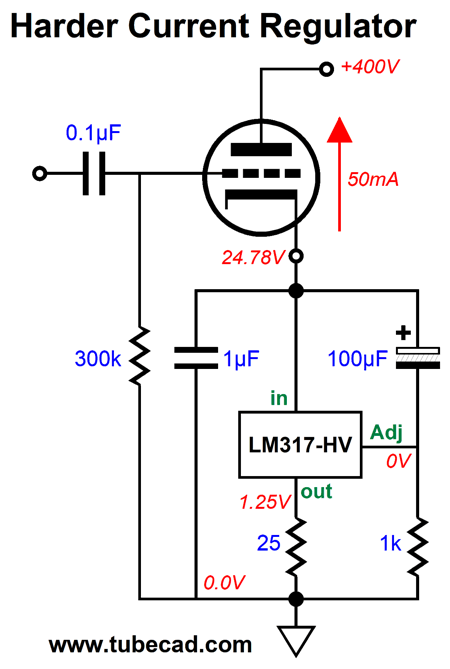
The 100µF capacitor and 1k resistor harden the constant-current source substantially in AC terms, while still preserving the DC auto-bias feature. The output tube's cathode is now AC coupled to the regulator's adjustment pin through the added capacitor. At the same time, the added resistor allows a DC path to ground potential (i.e. 0V). If the cathode voltage jumps up, the jump relays through the added capacitor to the adjustment pin, which then prompts the internal OpAmp force the voltage jump upon the 25-ohm resistor. Thus, the constant-current source's output impedance went from very crazy high (about 600k) to far lower (about 25 ohms), a 1/24k reduction. We can drop the output impedance even further by bypassing the 25-ohm resistor with a 1kµF capacitor. For less than $1, we can buy an aluminum organic polymer 1kuF/2.5V capacitor.
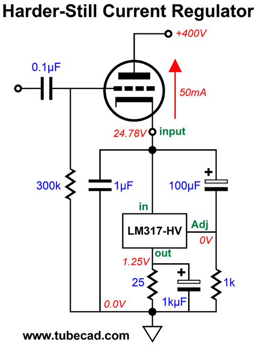
How low does the output impedance drop? In SPICE simulations, to about 7 ohms at 20Hz; with a 10kµF capacitor, 0.8 ohms. The way the circuit works is that the jump in voltage at the cathode forces the regulator to respond by pulling down its input voltage to restore 0V at its adjustment pin, thereby countering the jump in cathode voltage. We can further the hardening at ultra-high frequencies by adding a high-quality cathode capacitor, such as the 1µF capacitor in the schematic. Now, if an ultra-fast jump in cathode voltage occurs, the new capacitor will fight against it. We could further hot-rod this arrangement by adding a PNP transistor and resistor, which will unload the voltage regulator, but not appreciably lower the output impedance—if at all.
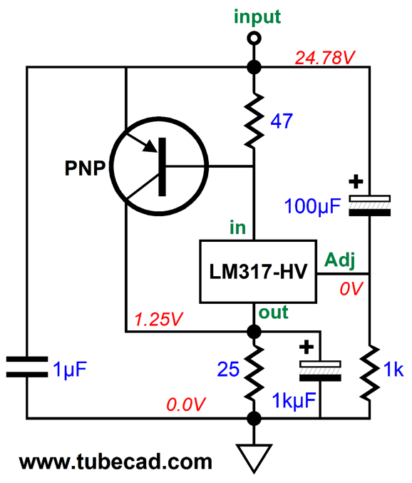
The PNP transistor draws most of the current flow into the output tube's cathode, but it is enslaved by the voltage regulator. Note how the PNP transistor's collector terminates into the bottom resistor, not ground. If it had terminated into ground, then the regulator could not monitor the current flow through the transistor. Of course, we could use a P-MOSFET in place of the PNP transistor. While the MOSFET is sure to offer less transconductance than the transistor, we could use a much larger resistor between its source and gate, say 470 ohms rather than 62 ohms, which could result in even greater effective transconductance from the MOSFET. In addition, MOSFETs just seem to prove more reliable and robust in actual use.
Before leaving the topic of three-pin voltage regulators, we should look at the negative regulator alternative, the LM337. One problem we face is that the LM337-HV is no longer made and the LM337's voltage limit is 37V; still, for some output tubes, such as the EL34 and EL84, this is not a problem.
Yes, it looks much like the LM317 version stood on its head. One big advantage the LM337 enjoys is that its tab is electrically attached to its center pin, the input-voltage pin, which in this circuit is grounded. Therefore, we can attach the tab directly to the metal chassis, forgoing the need for a heatsink and insulating washer. (Not that I would ever do so, as I like to keep my signal ground centered anywhere other than the chassis.)
By the way, here is the fleshed-out version of the LM337-based circuit.
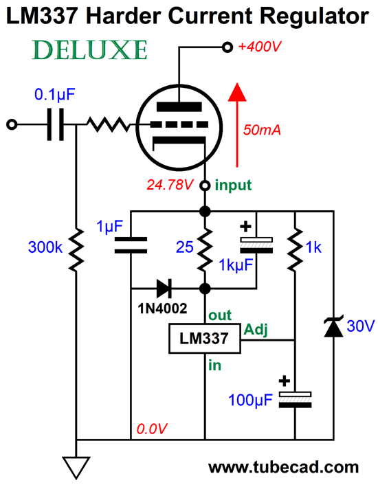
Note the added diode and zener. The 1N4002 rectifier provides a discharge path for the 1kµF capacitor at shut-down The 33V zener protects the LM337 from over voltage and provides a discharge path for the capacitors at shut-down.
We can use discrete electronic devices in place of the IC regulators.
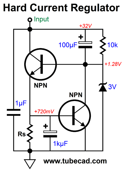
The bottom transistor monitors the current flow through the top transistor through resistor Rs, which in this example was 15 ohms. We can use different technologies, as in the following example.
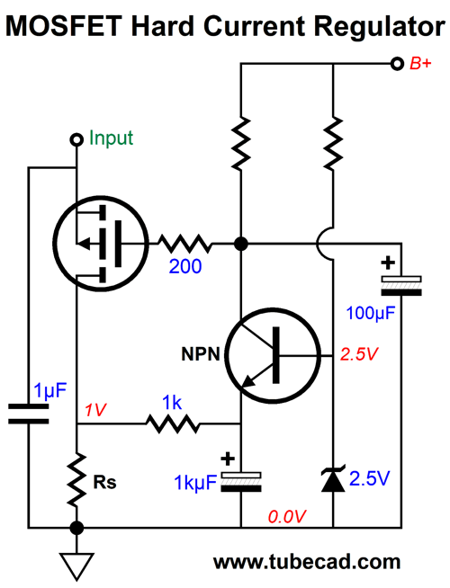
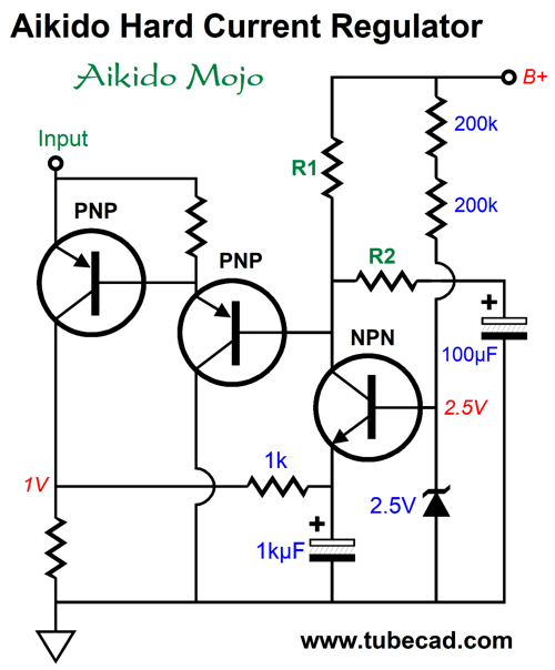
The NPN transistor is configured as a common-base amplifier that monitors the current flow through the P-MOSFET through the current-sense resistor, Rs. The 100µF capacitor delivers a clean DC signal to the MOSFET's gate, while the 1kµF capacitor smoothes away the AC signal that the NPN transistor's emitter sees. The voltage reference can be an LM431 shunt reference. We can get fancier still by imposing some Aikido mojo.
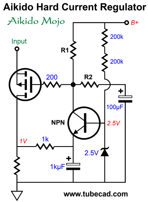
If you prefer bipolar transistors, the following circuit is for you.
Resistors R1 and R2 define a two-resistor AC voltage divider that reduces the amount of B+ voltage noise to 1/mu of the output triode used. For example, if the single-ended output stage uses a triode with a mu of 4, then one fourth of the power-supply noise must appear at the output tube's cathode in order to create a power-supply-noise null at the secondary. See post 229 for more details.
I mentioned the LM431 (aka TL431) and it could be used to create a hard constant-current source. The LM431 is a shunt-regulator IC that holds an internal 2.5V voltage reference and OpAmp and NPN transistor.
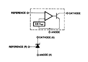
It strives to see 2.5Vdc at its reference pin and varies its current conduction to bring about this voltage. We must invert the phase at the LM431's cathode, as we are forcing a cathode bias, not a grid bias.
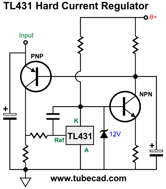
The NPN transistor both inverts the phase and provides some additional gain. The collector resistors and the 100µF capacitor form an RC filter that delivers a clean DC signal to the PNP transistor's base. The 12V zener protects the LM431 from over voltages. Here is the circuit in use.
Of course, we could inject some Aikido mojo by adding just one more resistor.
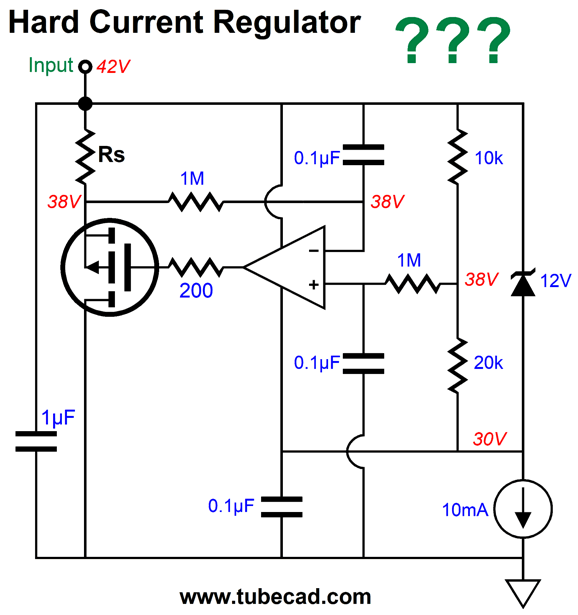
Another possibility is to use a high-voltage OpAmp to make a hard CCS.
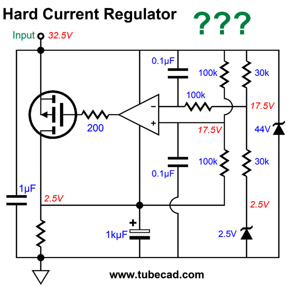
The "???" marks that I haven't run any SPICE simulations on the circuit. Bear that in mind. The way it works is that the 2.5V zener voltage drop must be matched by the voltage drop across the MOSFET's drain resistor. Therefore, we set the idle current by dividing 2.5V by the resistor value. (A trivial amount of current flows through the two 30k resistors and zener.) If the cathode tries to move off voltage, that movement will be relayed to the OpAmp's inverting input, which is then compared to the non-inverting input, which is grounded in AC terms. Here is a variation.
Not only are fewer parts used, but the OpAmp can be a normal low-voltage type, preferably with an FET input stage. Two current paths are provided, so we must add the 10mA to the current flow through the current-sense resistor, Rs. If actually building this hard constant-current source, I would add two protective diodes to the OpAmp's inputs, as we do not want the two inputs to stray from each other in voltage at startup.
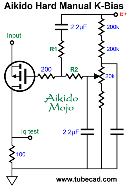
By the way, we could make a manual cathode-bias setup easily enough. Indeed, we can even introduce some Aikido mojo. First, let's look at an Aikido single-ended OPS.
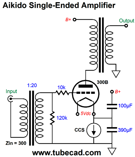
The 300B output tube's amplification factor (mu) is roughly 3.9, so the capacitors impose a ratio of 1:3.9.
I strive to avoid letting a DC current ever flow through a potentiometer's scraper, which the above circuit does not permit. The resistor ratio between resistors R1 and R2 is the inverse of the capacitor ratio, so we would use 390k for R1 and 100k for R2.
By the way, CCS are sometimes used to cathode-bias push-pull output tubes.
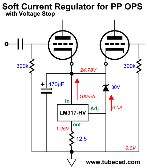
If the output tubes run in strict class-A, then the 470µF
capacitor
is not needed. Few output stages are run in class-a, however, ad copy to the contrary. Most are run in class-AB. This means as the input signal rises, the output tubes will leave the class-A window of current conduction, which will charge up the bypass capacitor, thereby raising the cathode voltage and reducing the idle current. The zener places a halt on how high the cathode voltage can rise. This setup is much like the old Brook amplifier.
Post 128 covers this amplifier and provides an OCR of the original article in the form of a PDF. Here is a quote of me from post 128:
Sixty years ago, this interesting and fun-to-read article appeared in Audio Engineering magazine (the precursor of Audio magazine). Written by J. R. Edinger, of Brook Electronics, the article lucidly explains how the push-pull Brook amplifier uses a dynamically shifting bias voltage to create an output-mode-shifting amplifier. Simply put, the Brook amplifier offers two faces: a push-pull, class-A, low-distortion, low-power amplifier, when at idle or under low signal levels; and a lean, mean class-AB, higher-distortion, high-power amplifier when provoked by large input signals. Now, this is the right sort of split personality; it’s much like having a fun, obedient, and loving dog who will turn into a fearless, frothing, flesh-tearing guard dog only when a loathsome intruder creeps into your house late at night.
The only real problem with this approach is that the output tubes must be tightly matched. A smaller problem is that the zener value must be found from experimentation.
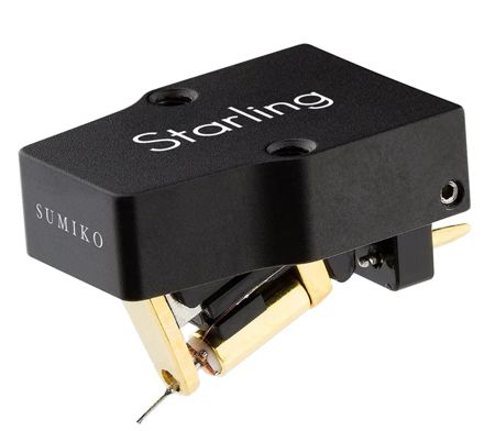
A friend is having problems with his moving-coil cartridge. He is not alone. Moving-coil cartridges are seldom plug-'n-play. I own a moving-coil cartridge, but it is a high-output Dynavector 10x5 Mk2 that delivers close to 3mV of output, so I have no problems using 40dB phono stages. The only concession I had to make was using a 10k load resistor rather than 47k. Most of my friends who run low-output moving-coil cartridges use step-up transformers, not active pre-preamps, although most have tried active gain stages before. Does this mean that transformers are intrinsically better? No, not necessarily. Most of my friends are also tube-loving people. In contrast, most MC pre-preamps and phono stages that offer gains of 60dB or higher are pure solid-state. Perhaps, if a high-quality tube-based pre-preamp existed, they would switch from their transformers to it.
I remember back in the 1970s that many were using tube-based MC pre-preamps, usually based on the 6DJ8. The circuit was amazingly simple, a grounded-cathode amplifier that held two triodes in parallel. The power supplies used, however, were often supremely complicated high-voltage regulators, something I found silly. Silly? Why go to all the trouble to design and build a fancy high-voltage regulator when the same effort could have produced a fancy high-voltage constant-current source? The constant-current source would deliver higher gain than any plate-load resistor could. In addition, the high-voltage constant-current source would shield the plate from the power-supply noise just as effectively as would the high-voltage regulator.
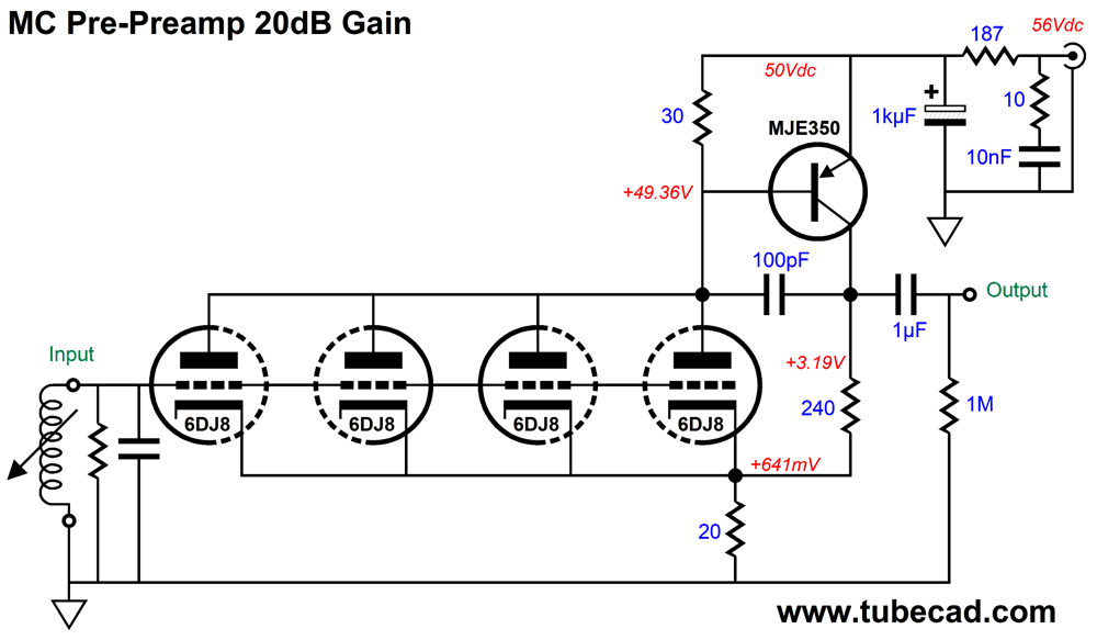
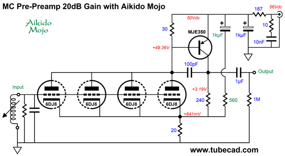
The interesting part was the doubled triodes, which reduces tube noise by -3dB. Four triodes in parallel are -6dB quieter than a single triode. This got me thinking about making an MC pre-preamp that held four 6DJ8 triodes in parallel. We could opt for a constant-current source plate load, but another possible arrangement would be a hybrid compound circuit with a high-voltage PNP transistor, the MJE350. Here is what I came up with:

Click on schematic to see enlargement
First of all, note the low B+ voltage and the low-resistance resistors used. The idea here is that we could make use of 56Vdc tabletop-switcher power supplies. The 10-ohm resistor in series with the 0.01µF capacitor is there to convert high-frequency hash into heat. The 187-ohm resistor forms an RC filter with the 1kµ/63V capacitor, which scrubs the DC clean. The 240-ohm and 20-ohm resistors define the negative feedback loop and set the gain to 1:10 or 20dB. The 100pF capacitor improves the high-frequency phase response and limits the high-frequency bandwidth to about 200 kHz. Here is the SPICE generated Fourier graph for 10mV of output at 1kHz.
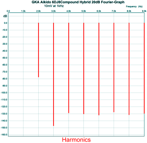
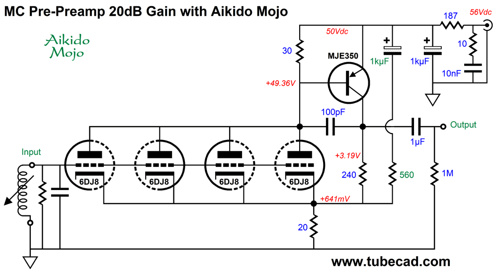
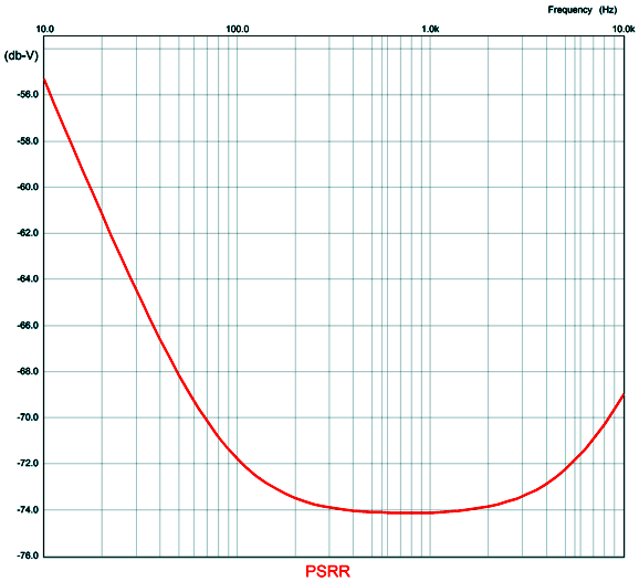
Mercy, not bad at all. Note the insane reduction of the 3rd harmonic and the strong 2nd harmonic. The PSRR, however, was only -9dB. The workaround is to add some Aikido mojo.
Click on schematic to see enlargement
The added capacitor and resistor inject a small portion of the power-supply noise into the cathodes, which prompts a power-supply noise null at the output.
Note that the null extends down to close to 100Hz. Well, this got me thinking: what if we made an all-tube Aikido version?
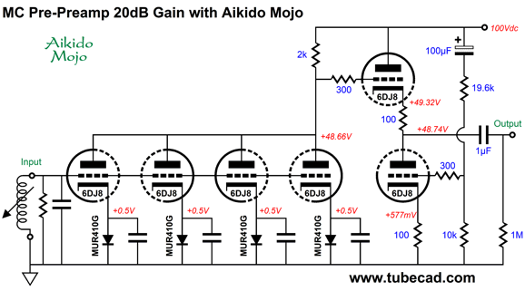
Click on schematic to see enlargement
A plate resistor is used instead of four triodes. An Aikido cathode follower (ACF) then scrubs away the power-supply noise from the input stage's output signal. Note that cathode resistors are not used; in their place we use four MUR410G rectifiers, each bypassed by a film capacitor. By the way, the circuit actually delivers a gain of 26dB, not 20dB. Here is the Fourier graph of 10mV of output at 1kHz.
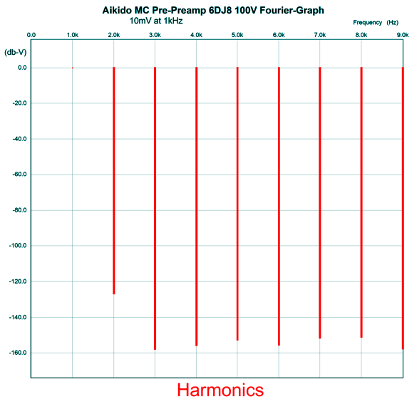
Wow, even better than I expected. How about the PSRR?
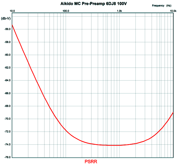
Just as good as the hybrid version with Aikido mojo.

Recently, I have been hunting down and listening to Australian composers. Yes, they do exist and they are well worth hearing. One example is Peter Sculthorpe, whose Requiem I found quite interesting and compelling. I noticed Brett Dean's name on the lists of Australian composers worth checking out; justly so, it turns out. The BIS label always delivers the sonic goods, which was enough to make me give this album a listen. Impressive. Well worth hearing.
//JRB
Did you get your money's worth with this post by me? If so, think about supporting me at Patreon.

  
Just click on any of the above images to download a PDF of the user guides.

For those of you who still have old computers running Windows XP (32-bit) or any other Windows 32-bit OS, I have setup the download availability of my old old standards: Tube CAD, SE Amp CAD, and Audio Gadgets. The downloads are at the GlassWare-Yahoo store and the price is only $9.95 for each program.
http://glass-ware.stores.yahoo.net/adsoffromgla.html
So many have asked that I had to do it.
WARNING: THESE THREE PROGRAMS WILL NOT RUN UNDER VISTA 64-Bit or WINDOWS 7, 8, and 10 if the OS is not 32-bit or if the OS is 64-bit.
I do plan on remaking all of these programs into 64-bit versions, but it will be a huge ordeal, as programming requires vast chunks of noise-free time, something very rare with children running about. Ideally, I would love to come out with versions that run on iPads and Android-OS tablets.
|