| John Broskie's Guide to Tube Circuit Analysis & Design |
20 March 2021 Post Number 532
Bipole Electrostatic Speaker
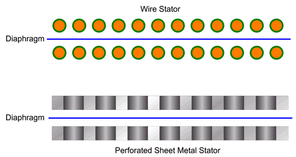
Second, some personal history: over many decades, I have noted that I preferred the sound emerging from electrostatic loudspeakers that used sheathed-wire stators, more so than the sound released from the standard stators made from perforated-sheet-metal. This preference was in opposition to my prejudice against the wire stators. Prejudice? I disdained the labor required in their construction, as each strand of wire must be stripped at each end and soldered at each end. In addition, each wire must be strung taut and carefully spaced with its adjoining wire. In addition, if you end up deeply nicking the wire while stripping away its outer covering, the wire is likely to break eventually at the nick. That's a lot of work. Still, the proof is in the listening. What could explain the better sound? I can only guess.
One guess is that the wire's round cross-sectional aspect simply makes a less obtrusive and obstructive barrier to the sound waves leaving the diaphragm. In contrast, a perforated metal stator exposes a mix of flat surfaces and sharp open holes through which the sound wave must clumsily navigate. In addition, the wire's diameter is far smaller than the distance between holes in perforated sheet metal.
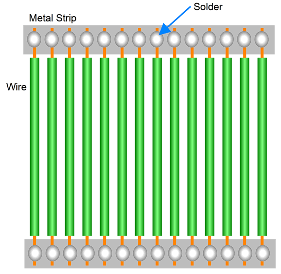
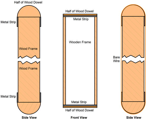
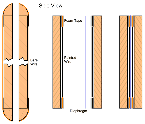
Well, this got me thinking that there must be an easier way to make an electrostatic loudspeaker with wire stators. For example, what if we used bare copper magnet wire, which we would only coat in non-conductive paint after the wires were soldered in place. This led me to the idea of making two stators at once. Imagine that we continuously wind bare wire around a tall rectangular frame; then, we solder the wires to long horizontal metal strips at the top and the bottom of the frame, one pair of metal strips on each side of the frame. Winding is easy. Stripping away sheathing and cutting each wire is hard.
We could wind the wire along with an equal length of fishing line, so the spacing between wires would be set by the fishing line's diameter. After the winding was complete, we would unwind the fishing line, leaving the wire perfectly spaced. The next step would be to solder the wire to the metal strips at the top and bottom, possibly with a butane torch. Once the wire was securely soldered, we would cut the frame in half lengthwise, then remove the dowel pieces and trim the wires, thereby making two stator structures. The next step would be to mask off the frame and apply non-conductive paint to the bare wire
This might work, but it, too, seems to require plenty of effort, as we would still have to make hundreds of solder joints. In a flash, it hit me that we could get away with using sheathed wire and making only two solder joints, one at each end of the frame-wound wire. A uni-stator. How could this possibly work? Don't we need two electrically separate stators? It could only work if we used an inner stator and two diaphragms, both of which would function in phase, thereby making a bipole loudspeaker, not a dipole. Almost all electrostatic loudspeakers are dipoles, with the sound leaving the backside out of phase with the sound radiating from the front.
Dipoles create sound nulls at their sides, as the two anti-phase sound waves cancel at the sides. In contrast, a bipole loudspeaker radiates in-phase sound from both sides, so no cancellation occurs at their sides. At low frequencies, bipoles are omnidirectional; at high frequencies, truly bipolar.
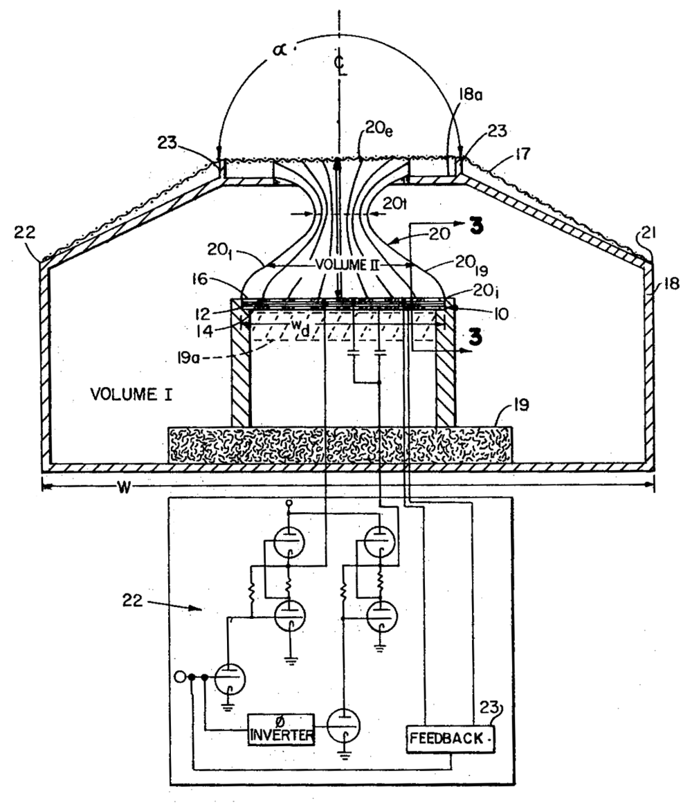
The only exception to dipole electrostatic speakers that I can think of is the old Beveridge electrostatic loudspeaker, which used an acoustic lens on the electrostatic panel's front and a sealed enclosure on the panel's rear. In other words, this was a monopolar loudspeaker, with sound emerging only from the front of the speaker.
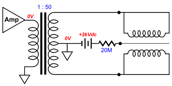
By the way, Harold Beveridge was a genius. His design (US Patent US3668335A ) is a brilliant masterpiece that rewards hours of devoted study. For example, he drove both the diaphragm and the stators and employed ultra-high-frequency negative feedback in the direct-coupled tube-based internal power amplifier to control the diaphragm's movements. Truly brilliant. His son continues his late father's work by building and selling electrostatic loudspeakers based on his own new designs. How do you drive both the diaphragm and the stators?
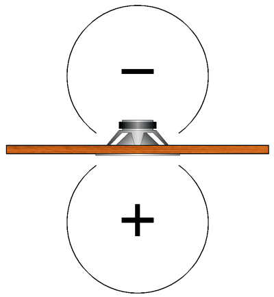
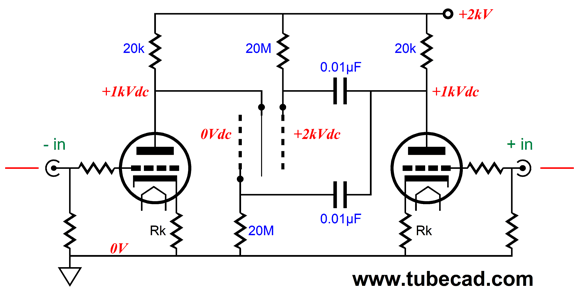
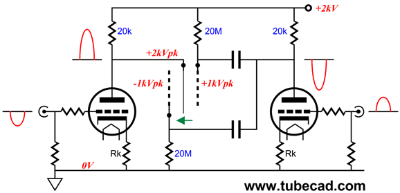
Yes, both stators see the same signal, differing only in their starting bias voltage. With this setup, the diaphragm must present a low resistance, not the usual ultra-high-resistance. Note that with no audio signal, the diaphragm is equally attracted to both stators. Now, let's introduce audio signal.
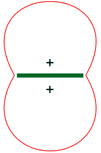
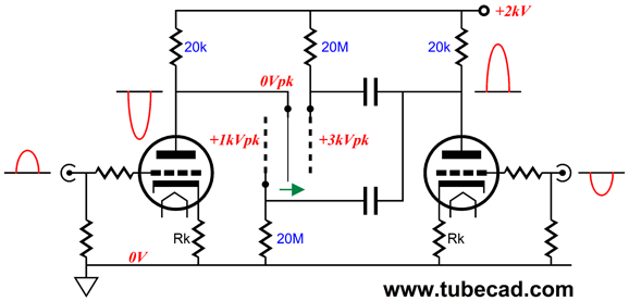
Note the voltage potential between diaphragm and stators. Now, we see the other half of the sine wave.
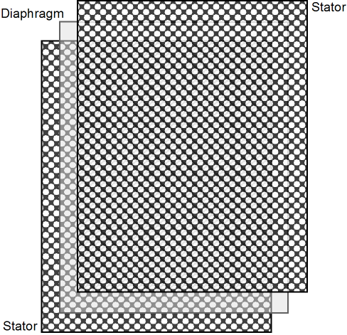
Once again, note the voltage potential between diaphragm and stators. Let's return to the bipole electrostatic speaker. Because the in-phase sound from both sides of the bipole does not cancel, we do not have to make the speaker panel as wide as possible to get low bass reproduction. In other words, a fullrange bipole electrostatic loudspeaker might be only 12 inches wide, not six-feet wide. Okay, how would we arrange the two diaphragms? The sandwich would consist of the outer wire stator then a diaphragm and then a non-perforated metal stator (possibly double-sided PCB material) then another diaphragm and then the same outer wire stator.
The inner stator and the outer wire stator attach to the secondary of a step-up output transformer, while the two diaphragms receive the same high-voltage bias voltage through high-resistance resistors. Wait a minute, John, the outer wire stator will present a huge inductance due to its many parallel turns. Actually, no. It may look like an inductor, but it fails to meet one essential inductor feature. Inductors impose inductance only when current attempts to flow through the inductor. In contrast, this outer wire stator has both ends of the wire soldered together, so no current flows from one end to the other; instead, the entire structure electrostatically fluctuates in voltage from the transformer's secondary.
The outer wire stator will still, however, develop a capacitance between itself and the inner metal stator; this capacitance will require current to charge and discharge during the huge audio signals, just as conventional perforated stators do. The two diaphragms radiate in phase into the listening room and also into the gaps between the diaphragms and the center stator. These two trapped air pockets function like an acoustic-suspension speaker enclosure. And as a result, the bipole electrostatic speaker may suffer from the same liability: restrictive low-frequency reproduction. Think about a dome tweeter, which also fires backwards internally, sometimes into a smaller felt dome, sometimes into a hole in the magnet structure, yet the tweeter has no problem producing high-frequency output. Effectively the trapped air acts as a capacitor that allows the easy creation of high-frequency bandwidth, but limits bass frequencies. One workaround would be to use two inner acoustically porous stators and space them far enough apart to create a larger volume of trapped air.
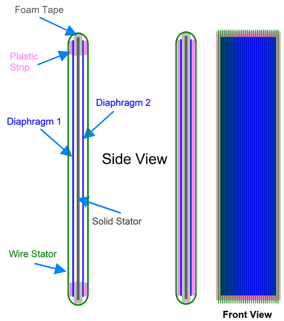
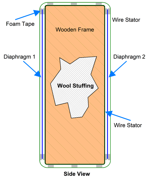
This arrangement still produces a bipolar radiation pattern and would allow lower-frequency bandwidth. The space between the two inner stators could be filled with sound-absorbing material, such as wool. Since I oppose using perforated stators, the two inner stators could also be made from wound-insulated wire. In other words, we would take a tall rectangular frame, either wooden or plastic, and wind insulated wire around the structure, either vertically or horizontally, and then frame the front and back with adhesive foam tape, to which we would adhere two stretched plastic film diaphragms. Next, we would apply another set of adhesive foam tape to the diaphragm and then wind the outer wire stator. Such a structure is inherently stable. In addition, the bipolar radiation cancels any anti-phase panel movement, as the in-phase diaphragm excursions cancel. We could even make a tall cylindrical electrostatic loudspeaker by winding insulated wire around two round disks separated by four long vertical rods.
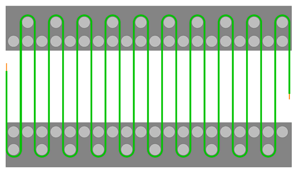
Prior to winding the inner stator, we could fill the center of the cylinder with acoustically absorbent batting or foam. After the inner wire stator is wound, we would adhere adhesive foam tape into a halo around the top and bottom of the cylinder; then we stretch the diaphragm vertically and adhere it to the tape; next, more tape and more winding of wire. We have all heard curved electrostatic panels, but who has heard a cylindrical electrostatic loudspeaker? Okay, what if these ideas are a bit too out there? Another idea I had was that we really do not have to make hundreds of solder joints. What if we had an array of pegs protruding from either a metal or plastic strip, around which we could wrap a long length of sheathed wire. Think of Lego blocks. Once we had all the wire in place, we would use glue to hold it tight.
Having the second array of fewer pegs above and below the array of spacing pegs is a subtlety. Wire does not want to make such a tight turn, so placing the winding peg up and away from the wire spacing pegs allows the wire make the turn more gracefully. In addition, it would prove easier to wrap the wire away from the centering pegs.
Well over a decade ago, I had this idea and I have asked several knowledgeable friends if this idea could pass the sniff test. In other words, could we generate a sufficiently strong magnetic field to get enough SPL from a resistive diaphragm? I got no answers, so I am asking all of you.
Let's start with 16 gauge magnet wire. (Since we are not dealing with high-voltage AC signals, but low-voltage DC current, sheathing is not required, as there is no shock hazard.) Bare copper wire is a little over 1/20th of an inch in diameter; with a varnish coating, about 0.052 to 0.053inches in diameter. Thus, we can get 10 turns per inch and still leave enough of a gap for the sound to pour through. If we made a dipole panel 24 inches wide and 72 inches tall, we would need 2900 feet of wire. Now, 16-gauge wire presents a resistance of 4.009 ohms per thousand feet, so we multiply 2.9 by 4.009 and get a resistance of 11.6 ohms. Well, we do at 20C, but as the wire will get slightly warm due to the extreme current flow, let's assume 12 ohms of resistance. Now, if we use a 48Vdc switcher power supply to drive the huge coil with DC current, the DC current flow will equal 48V divided by 12 ohms, or 4A. The wire will dissipate 4A against 48V or 192W, which may seem like a lot of heat, but remember that each turn of wire is surrounded by air and the loudspeaker stands upright, so convection airflow will wick away the heat. Another way of thinking of it is to realize that each foot of wire will dissipate only 66.2mW of heat. The next step is to find the formula for the magnetic flux of a solenoid. The equation is: B = μ I N/L Where: μ: permeability; B: magnetic field; I: current; N: number of turns of the wire; and L: Length of the solenoid. We plug in the values and get a wimpy 0.002 Teslas, which only equals 20 Gauss. This gives us a very low BL factor, as the length of the diaphragm is only 1.8 meters. At the same time, the surface area is huge, at 1.8 square meters or 1728 square inches. (A 10-inch woofer, in contrast, presents only 0.035 square metersؙ—or fifty times less.) In other words, we do not need a lot of force and movement to make a lot of sound with such a large diaphragm. Speaking of the diaphragm, I was thinking of metallized polyester film in a thickness of 0.002mm, which offers a resistance of 1.5 ohms per 100 square inches. My quick calculations resulted in about 4 ohms for a 24 by 72 inch diaphragm. Other possible material is Kapton flexible PCB material, but its resistance is far lower due to the 0.5 oz. copper coating. They do make copper metallized polyester film, which presents a resistance of 2.5 ohms per 100 square inches. This gets us closer to 8-ohms.
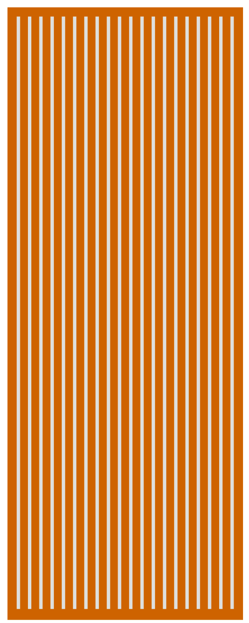
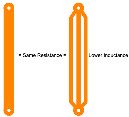
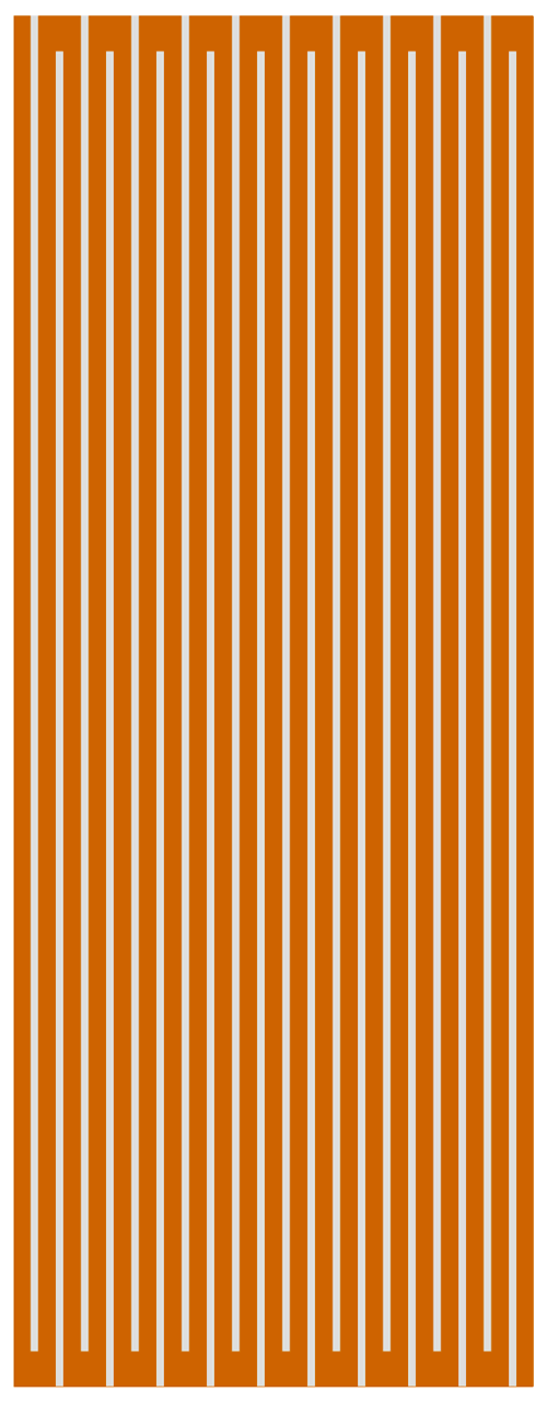
In fact, we can etch away long vertical lines of copper, leaving many long parallel lines of copper traces. This arrangement results in higher ohmage and lower eddy currents and lower inductance—all due to the etched gaps in copper. Lower inductance ? When arranging a PCB trace that must carry high current and offer low inductance, the best practice is not to use a single fat trace.
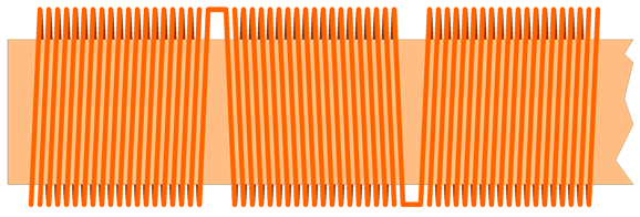
The segmented trace presents the same DCR, but a lower inductance. The same would hold true for the long segmented diaphragm. By the way, my original idea was to alternate the winding direction of the wire every inch, so a vertical zigzag trace could be used.
The flipped winding direction of the wire causes a flip in the north-south direction of the magnetic field. A zigzag layout of the long trace will also flip the interaction with the field, but as the two flips cancel, the diaphragm moves in the same direction.
Since the total length that the current must travel is equal to 72 x 24 or 1728 inches, the trace resistance must be a low 0.055 ohms per foot, which brings us back to flexible PCB material and heavy copper coating. At the same time, the long length will provoke 24 times more force in magnetic flux. Okay, the question remains: does this idea pass the sniff test?
More on MC Pre-preamp
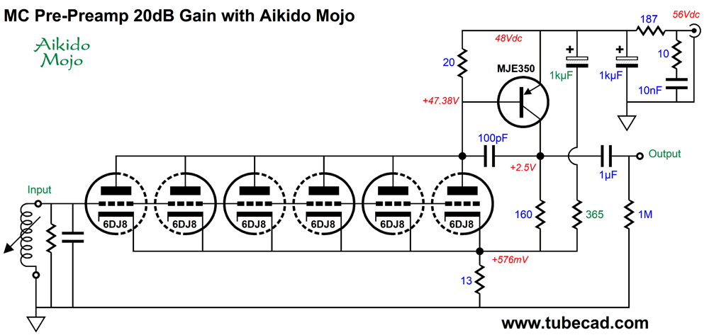
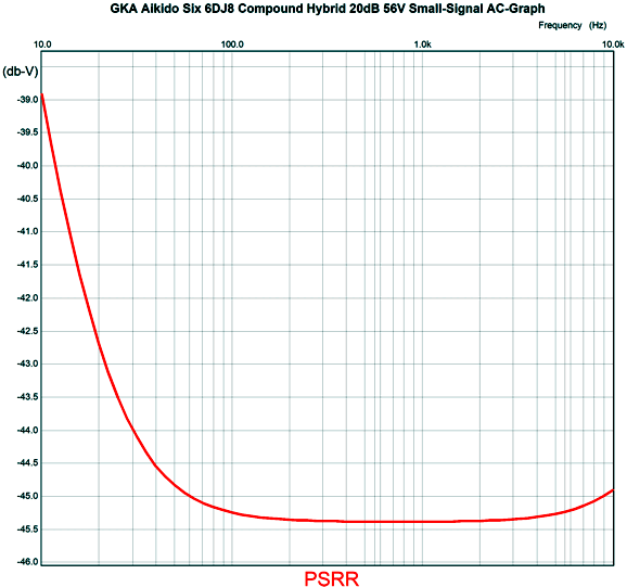
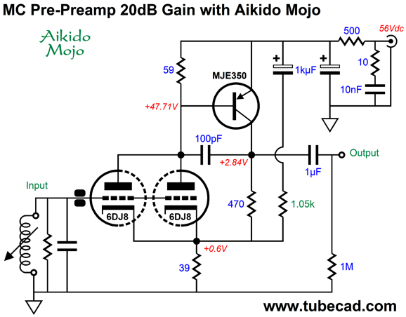
Not only will the six triodes lower the tube noise, but the total of six 6DJ8 heaters in series will require 37.8Vdc, which the 56Vdc power supply can easily supply; all that is required is a 50-ohm power resistor (two 100-ohm resistors in parallel) and a shunting capacitor, say a 1kµF 63V capacitor. Before leaving the topic of noise, note that the two negative-feedback resistors (13- and 160-ohms) are quite low in value. In fact, we must treat them as if they were in parallel, which yields only 12 ohms. One rule of super-quiet amplification is that the parallel resistance of the two feedback resistors should be lower than the source resistance. I believe most MC cartridges present an internal impedance of about 30 ohms, with some as low as 1 or 2 ohms. We would need many, many parallel triodes to get down to a 1-ohm cathode resistor. In other words, this pre-preamp should be used with a middle-output MC cartridge. The Aikido mojo enhancement improves the PSRR quite substantially. Here is the SPICE generated graph for the PSRR versus frequency without the RC filter.
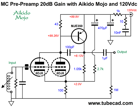
With the RC filter in place, the PSRR improves by 40 dB at 100Hz. Alas, I was embarrassed to discover mistakes in some of my previous SPICE simulations, wherein I forgot to switch off the power-supply-noise voltage sources; but I was also happy to realize that I had overlooked just how flexible one of my circuits was, as I saw how easily we could add the feature of adjustable gain. Asides from low-noise performance, selectable gain would prove a huge highlight of a pre-preamp. Why? MC cartridges offer a wide spread of signal outputs, some as low as 0.05mV and some as high as 3mV. Thus, the need for gain must also cover a wide spread of signal gain, say, from 6dB to 40db or, in voltage ratios, 1:2 to 1:100. That's some spread. In other words, one size is not going to fit all. Getting the gain right is important, as we do not want to overload the existing phono preamp, whose gain is usually 40dB (1:100). Bear in mind that the signal leaving the pre-preamp is not RIAA equalized, so the full high-frequency bandwidth appears at its output. (For example, a 20 kHz signal will be 40db greater in magnitude than a 20 Hz signal.) Looking at the compound arrangement, where we place several 6DJ8 triodes in parallel and use a PNP transistor to invert the phase and amplify the tube's signal, we see that the collector resistor sets the gain and that this resistor can be decreased or increased to vary the gain. Let's start with a hybrid compound MC pre-preamp with a gain of 20dB.
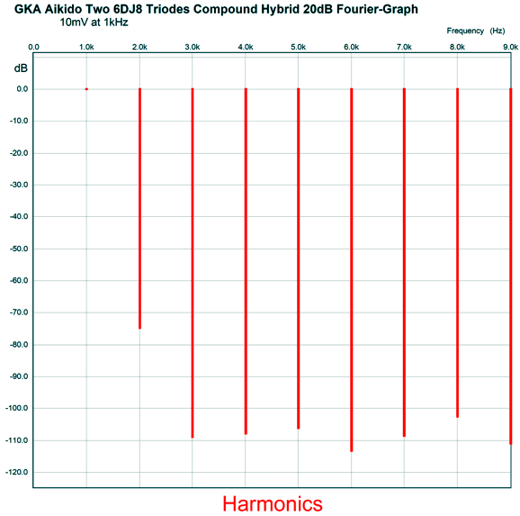
This simple circuit worked quite well in SPICE simulations.
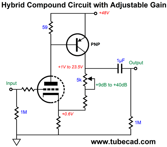
The PNP MJE350 strives to see a fixed base-to-emitter voltage, so varies its current conduction to establish a fixed current flow through the triode input stage. We can alter its collector resistor value without altering the input stage's idle current. With a collector resistor value of 0 ohms, i.e. a jumper wire, the amplifier ceases to be an amplifier and becomes a unity-gain buffer. At the other extreme, with a high-valued collector resistor, the amplifier's gain expands correspondingly. To make the gain variable we could replace the collector resistor with a potentiometer.
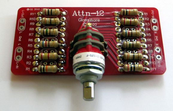
Since I never want any DC current to flow through the potentiometer's scraper, I would use a stepped attenuator instead, which would allow precise gain adjustments. In addition, the two channels would better track each other with fixed resistors. The stereo Atten-12 would be a good choice, due to its gold contacts. (If non-gold contacts are used, then the switch must be of the open-structure type, which would allow access to the contacts for easy cleaning with contact-cleaner spray.) We could easily apply an audio taper (aka logarithmic taper) to the array of resistors.
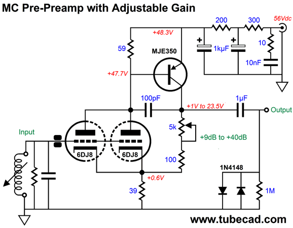
At one extreme, we get a gain of 1:3 (+9.5dB) to 1:40 (+40dB). Okay, let's now flesh out the circuit.
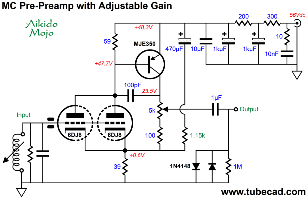
The two black rectangular blobs are the symbol for a ferrite bead, which is used to stifle RFI entering the pre-preamp. Since we are striving for the lowest possible noise, we cannot use the usual grid-stopper resistor. The two 1N4148 signal diodes are there to limit the maximum output voltage swing to about ±0.7Vpk. Since the potentiometer would only be used when a new cartridge or new phono stage was introduced, we do not have to worry too much about voltage jumps due to the selecting different gain settings. We do, however, have to worry about turn-on and turn-off thumps taking out a solid-state phono stage. (Schottky diodes, aka barrier diode or hot-carrier diode, offer even lower forward-bias voltages.) Note the cascading RC filters on the raw DC voltage. This is another nod to low-noise operation. Sadly, we cannot use the Aikido-mojo addition, as that technique assumes a fixed gain. Ah, it just hit me: we can still use the Aikido-mojo addition of resistor and capacitor and the two RC filters.
As far as the PNP transistor is concerned, the gain is 40dB. As far as the Aikido-mojo addition is concerned, the gain is 40dB. As far as the output is concerned, the gain is variable. Thus, the Aikido mojo obtains for all gain settings. One thought I had was that the hybrid compound circuit might work better with a higher B+ voltage, as that would prompt greater current flow from the triodes.
Each triode draws about 7.5mA; the PNP, almost 6mA. I was disappointed to see a drop in performance. Why? I had hoped to build a test circuit using my 12Vac PS HV and LV.
This power supply provides a regulated 12Vdc for the heaters and over 100Vdc of well-filtered B+ voltage. So, it looks like I will have to use the 56Vdc switcher power supply, of which I have several. Actually, this will force me to use a total of six 6DJ8s, which must prove quieter than just two. The tube noise decreases by the square root of the number of triodes in parallel.
Music Recommendation: Offertorium (By the way, Thomas Sterns Eliot included the "S" in his T.S. because T. Eliot backwards becomes "toilet." "Boobytrap" becomes... T. Eliot is an unfortunate semordnilap, which is itself a semordnilap of the word “palindromes.”)
I own one of the albums, T. S. Eliot's The Waste Land read By Robert Speaight, on the old Argo label, one of my favorite LPs. Speaight was a British actor who made many poetry recordings. I just love his voice and skill at reading poetry.
The version offered by Amazon Music is not based on master tape, but on the playing of the LP. Sadly, the transfer pales in comparison to my own old LP. Interestingly enough, Amazon offers P.J. Proby reading Eliot's The Waste Land. If you ever wondered what Eliot's poetry would sound like if read by a cowboy, this recording is for you. I liked it. Damn it, Eliot was born in St. Louis, Missouri, not London, so why not? My next turn took me to Germany. The late (2019) Swiss actor Bruno Ganz reads The Wasteland in its German translation. Wonderful stuff, in spite of my not speaking German. (Since the poem contains some German, I wondered if in the German translation those lines would be translated into English; they weren't.) We have seen Bruno Ganz at The Tube CAD Journal.
Yes, he was the actor who played Hitler in the 2004 movie, Downfall, which launched a thousand YouTube parodies. Well, they used to exist, but Hitler parodies are now officially verboten. I grew up watching the TV comedy show, Hogan's Heroes, which will no doubt soon be committed to the higher-awareness flames* as well. By the way, I once mentioned to my cousin that Werner Klemperer, the actor who played Col. Wilhelm Klink, was the son of the famous and great German conductor Otto Klemperer. He remarked, "To think that so much could have come from so little." Yes, it does run in my family.
Okay, returning to Bruno Ganz, his album is titled, Wenn Wasser wäre - T.S. Eliot / Giorgos Seferis. It's on the ECM label and available at Amazon Music. My last turn landed me at Sofia Gubaidulina: Offertorium concerto for violin & orchestra and her Hommage à T. S. Eliot, for soprano & octet. Gubaidulina was born on October 24, 1931, in Chistopol, in the Tatar Republic. She is concidered one of the best Russian composers after Shostakovich. Her music is new to me, but what little I have heard I have enjoyed. And I look forward to hearing more of her compositions.
//JRB
*Flames
User Guides for GlassWare Software
For those of you who still have old computers running Windows XP (32-bit) or any other Windows 32-bit OS, I have setup the download availability of my old old standards: Tube CAD, SE Amp CAD, and Audio Gadgets. The downloads are at the GlassWare-Yahoo store and the price is only $9.95 for each program. http://glass-ware.stores.yahoo.net/adsoffromgla.html So many have asked that I had to do it. WARNING: THESE THREE PROGRAMS WILL NOT RUN UNDER VISTA 64-Bit or WINDOWS 7, 8, and 10 if the OS is not 32-bit or if it is a 64-bit OS. I do plan on remaking all of these programs into 64-bit versions, but it will be a huge ordeal, as programming requires vast chunks of noise-free time, something very rare with children running about. Ideally, I would love to come out with versions that run on iPads and Android-OS tablets.
|
I know that some readers wish to avoid Patreon, so here is a PayPal button instead. Thanks. John Broskie
John Gives
Special Thanks to the Special 86 To all my patrons, all 87 of them, thank you all again. I want to especially thank
I am truly stunned and appreciative of their support. In addition I want to thank the following patrons:
All of your support makes a big difference. I would love to arrive at the point where creating my posts was my top priority of the day, not something that I have to steal time from other obligations to do. The more support I get, the higher up these posts move up in deserving attention.
If you have been reading my posts, you know that my lifetime goal is reaching post number one thousand. I have 471 more to go. My second goal was to gather 1,000 patrons. Well, that no longer seems possible to me, so I will shoot for a mighty 100 instead. Thus, I have 13 patrons to go. Help me get there.
Support the Tube CAD Journal & get an extremely powerful push-pull tube-amplifier simulator for TCJ Push-Pull Calculator
TCJ PPC Version 2 Improvements Rebuilt simulation engine *User definable
Download or CD ROM For more information, please visit our Web site : To purchase, please visit our Yahoo Store: |
|||


| www.tubecad.com Copyright © 1999-2021 GlassWare All Rights Reserved |