| John Broskie's Guide to Tube Circuit Analysis & Design |
10 November 2004
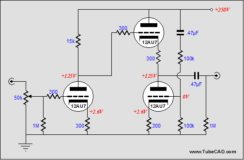
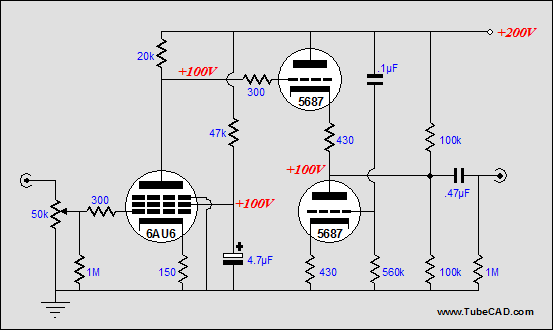
Well, after that last sermon (yesterday's blog), I'm sure many will welcome more circuit analysis. After having learned of reader Paul’s predicament with his Antique Sound Labs AQ-2004 line stage, I'm sure that a few readers have wondered how three 12AU7s could be used in the Aikido amplifier, as the circuit seems to require an even number of twin-triode envelopes. The answer lies in how the cathode follower output stage works: a conventional cathode follower is loaded by a quasi constant-current source that also works to buck the percentage of the power supply noise presented by the first stage. Now, if the input stage comprises two identical triodes that share identical cathode resistors, then the percentage of power supply noise will be 50%. This same 50% ratio, however, can be realized with one triode, if the cathode resistor’s value is carefully chosen. All that is required is that the plate resistor’s value be effectively equaled by the triode and its unbypassed cathode resistor. The total effective impedance of the triode and cathode resistor is equal to (mu + 1)Rk + rp Thus, when Ra = (mu + 1)Rk + rp the voltage division will be 50%. Solving for Rk, we get: Rk = (Ra - rp)/(mu + 1) (Once again, it is important to remember that the cathode resistor must be unbypassed.)
So, what we gain by using two triodes in the input stage is ease of use and universality. Laudable goals indeed, but there are times when another goal may trump (for example, more gain). In the balanced totem-pole configuration the gain is equal to the amplification factor (mu) divided by 2; whereas when the cathode resistor is bypassed, a grounded-cathode amplifier can deliver a gain much closer to the triode’s mu. Bypassing the cathode resistor will alter the power supply noise division, so the percentage of power supply noise injected into the cathode follower’s bottom triode will correspondingly be altered.
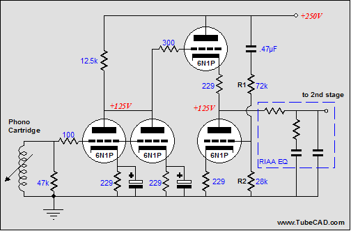
In the schematic above, we see basis of the first half of a tube phone preamplifier. The circuit begins with two 6N1Ps working in parallel into a common plate resistor. Each triode gets its own bypassed cathode resistor, which allows each triode to find its own quiescent idle current. Effectively, the two triodes act as one triode with the same mu and twice the transconductance (gm) and half the plate resistance (rp). At the specified plate voltage and idle current, these values become: mu = 36, gm = 7.5 mA/V, and rp = 4.8k. Thus, the 12.5k plate resistor is effectively in series with a 4.8k resistance, with a resulting voltage division of 28%. Therefore, the cathode follower’s bottom triode’s grid must be presented with 28% of the power supply noise, which 72k and 28k resistors yield easily enough.
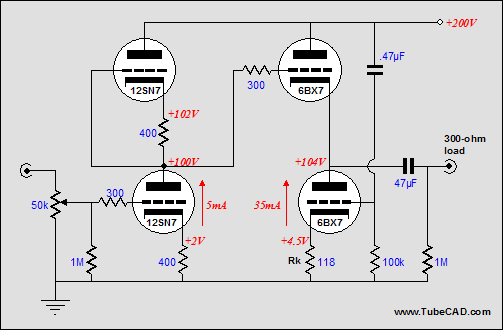
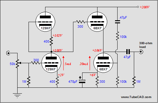
In the schematic above, we see a tube-based headphone amplifier. The intended load is 300-ohm headphones, such as those made by Sennheiser and others. The 6BX7 is a tough triode that can easily drive such a load. But how do we null out the power supply from the output? One way of looking at the output stage is to see the top triode as representing a plate resistor equal to rp/(mu +1), which in the case of the 6BX7 is about 118 ohms. Now, if we view the bottom triode as constituting a grounded-cathode amplifier with a plate resistor equal to 118 ohms, then we need to specify a cathode resistor whose value will result in a gain of 0.5, as its grid sees the full power supply noise. Thus, because grounded-cathode amplifiers invert the phase at their plate, we can null the noise at the output, thus: 0.5 – 0.5 = 0. Or another way of looking at this output stage is to see that if we halve the bottom triode’s effective gm, the top triode’s reaction to half of the power supply noise will be countered. The formula for effective gm (gm') is : gm' = mu / [rp + (mu + 1)Rk] Thus, half the gm results when rp = (mu + 1)Rk, or solving for Rk, when Rk = rp/(mu + 1). This works to null the power-supply noise at the output due to 50% of the this noise being presented to the top triode's grid from the preceding input stage, but it does not include the amount of noise current created by the top triode's rp. The math starts to get thicker here, alas. In the presence of power-supply noise, we must must establish an equilibrium between top and bottom current variations, which obtains when mu / 2rp + 1/rp = mu / [(mu + 1)Rk = rp] After some long algebraic dancing with the formula, we arrive at Rk = rp(mu -2) / (mu² + 3mu + 2) With this cathode resistor value, the power-supply noise at the output is nulled. Notice that we must accept the whatever idle current that results from this cathode resistor value and roughly half of the B+ voltage for the bottom triode. What if this idle current is excessive? How do we lower the current while still nulling the power supply noise?
Cascodes, pentodes, and FETs The cascode amplifier exhibits an exceedingly poor PSRR, so much so that just about all of the power supply noise will make it to its output. The same holds true for the average pentode and FET circuit (pentodes and FETs also have a small triode region of operation at low voltages). In the schematic below, a cascode amplifier cascades into our special cathode follower. Since the cascode stage will pass all of the power supply noise, we must deliver all of the power supply noise to the cathode follower’s bottom triode’s grid. 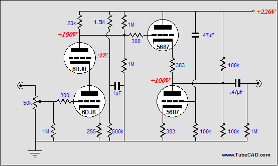 In the circuit below, a pentode has replaced the cascode. Once again, we inject all of the noise into the bottom triode’s grid to counter the noise at its plate.
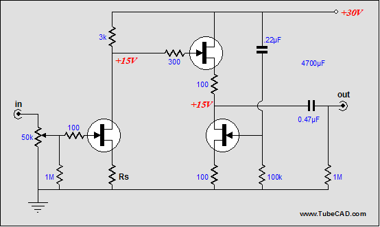
In the schematic above, we see an all-FET preamp. The gain will roughly equal the drain resistor divided by the source resistor, Rs. No matter what the final gain, however, all of the power supply noise will transfer to the top source-follower FET’s gate, so we must offer the bottom FET the same amount of noise. This is easily done by attaching its bypass capacitor to the B+ rail. (This is exactly opposite of what 99% of electronic designers would do, as they always ground bypass capacitors, even when it results in worse performance, as consistency is a seemingly higher goal or maybe it has something to do with old dogs.) Wait a minute. Couldn’t we use two FETs, each with its own source resistor, just like the equivalent tube circuit? In theory, yes; in practice, no. The FETs would have to be perfectly matched, which they never are, which means that they would not define a 50% voltage divider for the B+ voltage. Still, we could force the voltage division by adding a few parts. In the schematic below, we see the bottom input FET being loaded by a FET-based constant-current source, whose DC point is set by the two-resistor voltage divider. In this circuit, none of the power supply noise should make it to the second stage, so we do not inject any noise into the bottom FET. Additionally, in this circuit, the input stage realizes a great deal more gain, so much that a feedback loop has been added. (This circuit would make a fine moving-coil phono cartridge pre-preamp.) 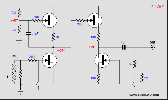
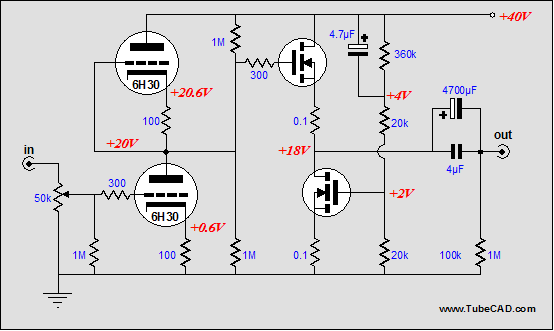
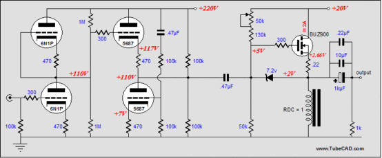
One problem with this hybrid is that we are asking a lot of the input stage, as it must deliver both high gain and a high current (for a tube) to drive the MOSFET’s input capacitance. Splitting these tasks between two tube stages (i.e. the Aikido amplifier) would ease the design of a good hybrid amplifier. Additionally, we can use a much higher B+ voltage for the tube stages than any solid-state output stage could handle. Below are a few single-ended Class-A hybrid ideas. (The MOFET source-follower output stages already enjoy an exemplary PSRR, so if we feed the a clean signal, we will not have to work to lower its noise contribution.) Returning to pentodes, the schematic below displays a simple transformer-coupled, single-ended headphone amplifier. (It could readily be scaled up to a real power amplifier). The output stage is configured as a cathode follower working into a transformer primary, but with a difference. The 47µF capacitor couples the power supply noise to the other end of the primary, so the primary never sees a noise induced voltage differential. The primary also serves as a cathode resistor of sorts to self bias the output tube. 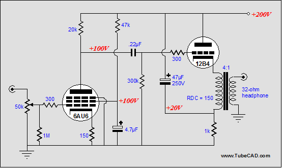 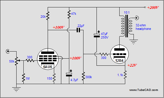 In this variation, we see the output stage configured as a grounded-cathode amplifier. This time the 47µF capacitor couples the power supply noise to the output tube’s cathode. The result is that the output tube does not “see” the power supply noise about it, as it plate and grid also equally see the same noise.
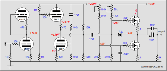
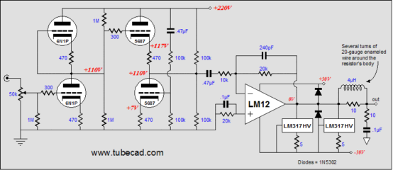
Just in case my solid-state e-mail falls off, here is a simple hybrid that uses an LM12 power OpAmp, but with a few twists. Of course, the tube front end counts, but the two LM317s add a nice twist: they are configured as constant-current sources that force the LM12's output stage to work in single-ended Class-A mode for the first watt, with push-pull Class-AB thereafter. //JRB
|
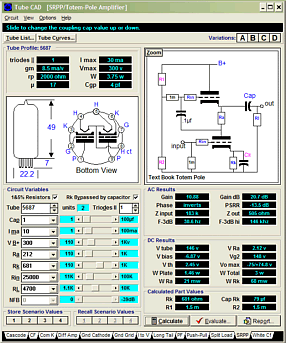
Tube CAD does the hard math for you. This program covers 13 types of tube circuits, each one divided into four variations: 52 circuits in all. Tube CAD calculates the noteworthy results, such as gain, phase, output impedance, low frequency cutoff, PSRR, bias voltage, plate and load resistor heat dissipations. Which tube gives the most gain? Tube CAD's scenario comparison feature shows which tube wins. Windows 95/98/Me/NT/2000/XP For more information, please visit our Web site :
|
|||
| www.tubecad.com Copyright © 1999-2004 GlassWare All Rights Reserved |

