| John Broskie's Guide to Tube Circuit Analysis & Design |
DC Coupled? |
||||
11 November 2004 DC Coupling Many were inspired by the simple hybrid circuits, with their few parts and their uncomplicated schematics and, yes, their DC coupling. “I could actually build this amplifier,” was the shared thought. In contrast, my thought was, “Someone might actually build this DC-coupled tube-MOSFET hybrid and, in the process, toast his expensive loudspeakers.” Simple does not necessarily equal safe. MOSFETs conduct within the microsecond the B+ voltage develops, whereas tubes take 15 to 30 seconds to heat up before they conduct; and loudspeakers, in the face of pure DC voltage, only need a few seconds to start smoking. Tubes can be yanked from their sockets, or only wiggled to lose contact—but with the same result: an output stage that slams and sticks to one rail voltage. Thus, my fear. As result, I have been questioning the near-universally held belief in the undesirability of using coupling capacitors to connect the loudspeaker to the amplifier’s output stage. 
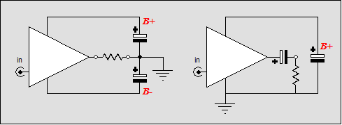
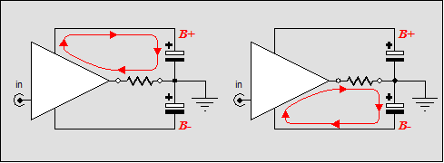
Contrary to popular opinion, coupling capacitors—at the amplifier’s output—can protect a loudspeaker from catastrophe. No matter how nasty the failure—a blown fuse, a shorted output device, a missing input tube, a rail-latched output stage—the loudspeaker is safe. As capacitors cannot pass DC current, a sustained DC failure is blocked by a coupling capacitor. (High-frequency oscillations are a different catastrophe altogether.) So why aren’t output stage coupling capacitors used more often? Two reasons immediately come to mind: added expense and bad publicity. Cost But what about amplifiers that hold only a mono-polar power supply, like the Futterman OTLs or early Dynaco solid-state amplifiers? Surely here the coupling capacitor is not redundant, but essential. True: the coupling capacitor would not be redundantly added, but the amplifier would be still more expensive to build than a comparable bipolar-power-supplied amplifier. Why? First of all, a stereo amplifier that holds a bipolar power supply needs only two power-supply capacitors, whereas a stereo amplifier that holds a mono-polar power supply would need one power-supply capacitor and two large coupling capacitors, for a total of three. And in the case of monoblock amplifiers, the total number of large capacitors equals two per amplifier regardless of power supply topology; however, the mono-polar power supply capacitor and coupling capacitor must be of much higher voltage rating—twice the bipolar power supply capacitor voltage’s rating, in fact. Higher voltage capacitors are much more expensive than lower voltage capacitors. For example, a 30-volt bipolar power supply might use two large power-supply capacitors holding 10,000µF of capacitance and a 50 volt rating; these caps cost $18.15 in the Digi-Key catalog. In contrast, a 60-volt mono-polar power supply might use one large power-supply capacitor holding 10,000µF of capacitance and a 100 volt rating and the same valued capacitor for coupling to the loudspeaker; these caps cost $23.51 in the Digi-Key catalog. Well, the mono-polar-power-supply amplifier seems to lose the cost battle—but does it really? A single 10,00µF and 100-volt capacitor actually holds twice the wallop that two 10,00µF and 50-volt capacitors, as the two capacitors are effectively in series with each other, thus halving the total effective capacitance of the pair. In other words, the two capacitors become a single capacitor with 5,000µF of capacitance, halving the potential wallop. The connecting to ground will hinder many from seeing this, so a different approach is to figure out the sum of energy (in joules) that the two capacitors hold when each is charged to 30 volts. The potential energy that a capacitor holds is measured in joules and the formula is: J = ½CV², where J = joules, C = capacitance, and V = voltage. Thus, if you double the capacitance, you double the joules; but if you double the voltage, you quadruple the joules. (If you ever wondered how a tube amplifier can get away with a 50µF power supply capacitor, this is why: voltage is more powerful than capacitance in a power supply, as 450 volts across 50µF of capacitance equals 5 joules.) Given 10,00µF and 30 volts, the number of joules equals 4.5 joules; and two capacitors hold a total of 9 joules. On the other hand, given 10,00µF and 60 volts, the number of joules equals now 18 joules. Therefore, on a joule-per-dollar basis, the higher-voltage capacitors are a better deal. Bad Rap 
At least with a coupling capacitor, because it is so obviously in the path, we are forced to consider its sonic contribution, prompting us to make amends, using a higher quality electrolytic capacitors and bypassing with film capacitors. In other words, I don’t believe that the average direct-coupled amplifier is as "capacitor- free" as the advertising department would like us to believe. First of all, if the issue is not coupling capacitors per se, but the use of electrolytic capacitors, why bother with electrolytic capacitors at all? Why not only use film capacitors? Other than size and cost, no reason at all. In fact, what could be more envy-inspiring than owning an electrolytic-free amplifier, especially a solid-state or all-tube OTL or hybrid amplifier that forswore electrolytic capacitors altogether? For a little less than $1,000 per channel, an all-polypropylene coupling capacitor can be had by paralleling audiophile-approved capacitors (budget capacitors, no less); or about $100, if you are willing to use Chinese-made polypropylene motor-start capacitors; or even less, if you are using the amplifier in a bi-ampped setup and the coupling can also waork as part of the crossover. For example, a 20µF capacitor is needed to set a 1kHz high-pass filter into an 8-ohm load. In other words, why not use a monopolar-PS amplifier that is going to see a capacitor coupled load anyway? //JRB
|
TCJ Push-Pull Calculator Rebuilt simulation engine *User definable
Download or CD ROM For more information, please
visit our Web site : |
|||
| www.tubecad.com Copyright © 1999-2004 GlassWare All Rights Reserved |


