| John Broskie's Guide to Tube Circuit Analysis & Design |
|
||||
12 November 2004 Gomes Vs XPP 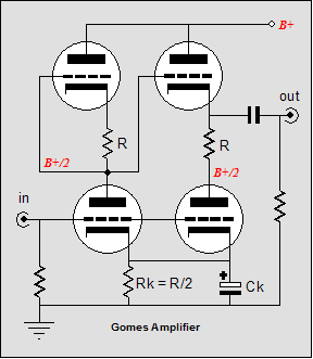
Versus: 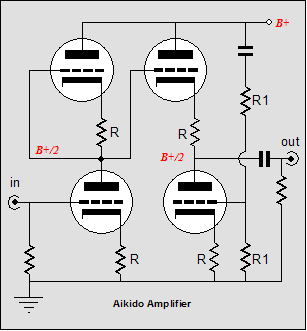
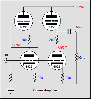
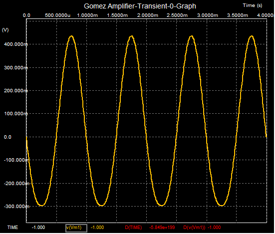
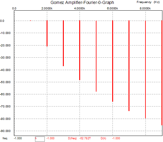
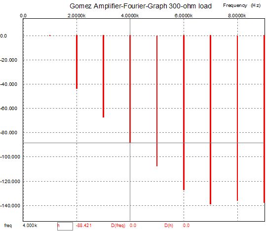
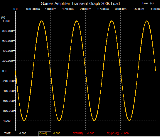
A closer inspection reveals two different stories. The Gomes amplifier is a push pull circuit, while the Aikido amplifier is a single ended circuit. In the Gomes amplifier, both bottommost triodes see the same input signal, while in the Aikido amplifier, the bottommost triodes do not share a common input signal, as the only signal the second bottom triode sees is the 50% of power supply noise. In the Gomes amplifier, the input stage's top triode sees no signal, functioning as an active plate resistor substitute, while in the Aikido amplifier, the input stage's top triode sees the amplifier's output as its input signal. In the Gomes amplifier, the second top triode sees all the signal offered by the first stage. Since this signal is in anti-phase to the signal the bottom triodes see, push pull operation results, wherein the load resistance receives the delta (the difference) in current conduction between top and bottom output tubes. In Aikido amplifier, however, the second top triode’s is also fed its input signal from the first stage, but the second top triode works alone, as the its bottom triode partner only acts as a smart load that works to null noise at the output. As far as I can make out, the Gomes circuit (aka Supertotem) is an alternative (answer to) to the SRPP. I should have covered the Gomes circuit in my article The SRPP deconstructed, as it fits perfectly in that analysis. The French magazine L'Audiophile in 1981 (issue 22), published a Portuguese audio designer Jose Gomes's push-pull 211 amplifier; unfortunately, I don’t have access to that issue. It is said to offer a better distortion and PSRR figure and a lower output impedance than a comparable SRPP circuit. I’m sure there's an improvement in at least output impedance, but at the cost of twice the tubes. Was it a good bargain? Unfortunately, the answer depends; it depends on what end you have in mind for the circuit. I have said many times here that the SRPP represents doing push-pull operation on the cheap, push pull without a separate phase splitter. The Gomes circuit comes in at a slightly higher price in terms of tubes used than the SRPP, but it is still not that close an approximation to perfect push-pull operation, which while not great, is not necessarily all that bad. Hint: the answer depends on the load. Extreme thinking 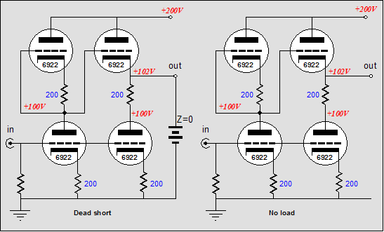 When I first saw the Gomes circuit, the first thought I had was what happens if the output is shorted to ground? (32-ohm headphones count as being close to ground in a tube circuit) Well, if the output is grounded, the bottom output triode sees X amount of input signal and the top output triode sees an input signal of -muX/2. In other words, a gross imbalance; the greater the mu, the worse the imbalance. (Unless a 6AS7, with a mu of 2, were used, which is another example of extreme thinking; the 12AX7 being at the other extreme.) Now at the other extreme, if the output is left open, i.e. no load whatsoever, the bottom output triode sees X amount of input signal and the top output triode sees an input signal of almost 0. What? Since the output stage realizes almost the exact same gain (with no load) as input stage, there is no real difference between the top triode’s grid and its cathode, other than the DC offset incurred by the cathode resistor. In other words, the circuit ceases to function in a push pull mode, as there no longer is any delta in current conduction. Of course, zero and infinity are not common loads in most audio applications, but 32 ohms can be. Below is the Gomes circuit’s schematic that is being simulated in SPICE and a graph of the output voltage into a 32-ohm load.
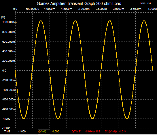
Not too shabby, about 1% distortion. Finally, we use a 300k load. something here?
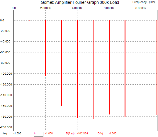
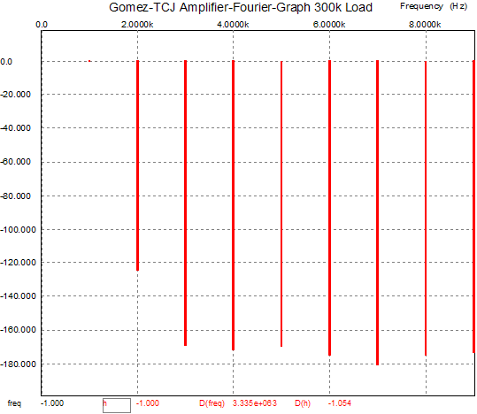
Much better, about 0.001% distortion at 1 volt out. No wonder this topology is getting noticed, but it is still not as good as it could be. How so? Stop, pull way back and look at the circuit. Now ask yourself, Why is the output taken at the top triode’s cathode? My guess is that it is no more than an SRPP affectation and nothing more. True, you do get a lower output impedance that way, but as the circuit isn't particularly good at driving low impedances, who cares. Will the 300k load care if it sees an output impedance of 300 ohms rather than 200 ohms? 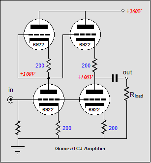
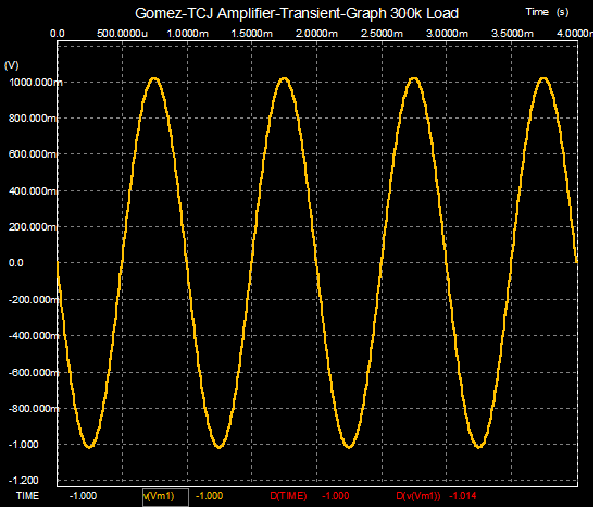
Moving the output to the bottom triode’s plate restores symmetry and yields better results, as shown in the graph below.
Much better still, about 0.0001% distortion at 1 volt out. As all circuits must have name (something that I have been forced to accept), let’s call this variation the Gomes-TCJ circuit. We will return to this circuit, but first let’s look into an alternative. The XPP amplifier Well, if we need a push pull amplifier, then let’s make sure that it works in a balanced fashion, that its output tubes see an equal but phase-inverted input signal. The XPP amplifier (I couldn’t think of anything cute) uses a few tricks to ensure balanced operation. In the schematic below, we see the X, the cross coupling of the two top tubes. The output is fed back into the input stage and the output stage receives its input signal from the first stage. (The "figure 8amplifier" would have been a good name as well.) 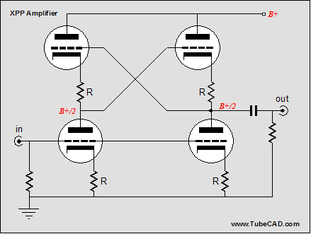
Now its time to think in extremes. First begin with a shorted output. In this case, the bottom output triode sees X amount of input signal and the top output triode sees an input signal of almost exactly -X. In other words, balance. How this possible? With the output grounded, the input stage’s top triode’s grid is also grounded. Thus, the plate load presented to the bottom triode is equal to rp/(mu + 1) + Rk, which in this schematic equals 297 ohms, which in turn yields a gain of –0.95. True, -0.95 is not equal to –1, but compared to –16.5, which the Gomes circuit yields with a grounded load, it is darn close. To get an exact –X worth of input signal, the top cathode resistor would have to be a shade bigger. How much bigger? The top cathode resistor would have to equal [(mu + 1)Rk + rp] / ( mu – 1) - rp/(mu + 1) But, I would not bother making any adjustments with any high-mu triodes, as the difference shrinks with mu. (Maybe I would play with using two bottom cathode resistors in series, one bypassed, the other not, the total resistance equal to the top cathode resistor.) 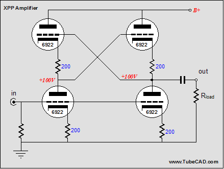
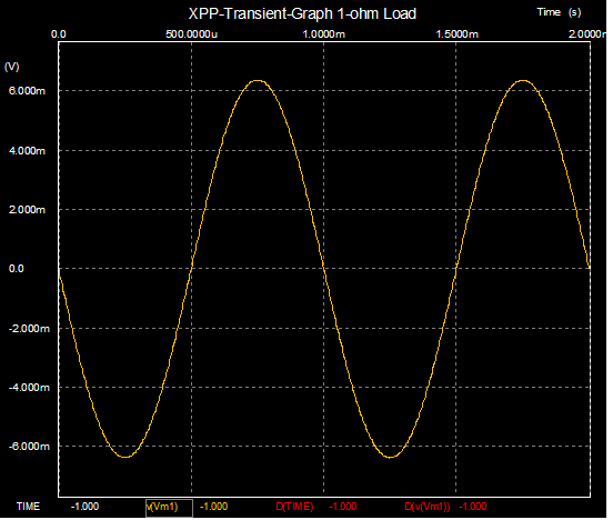
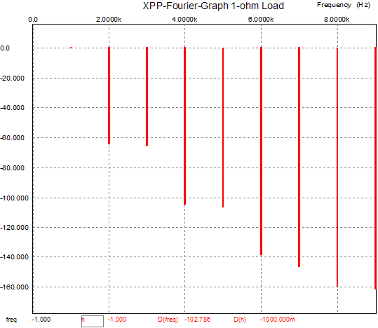
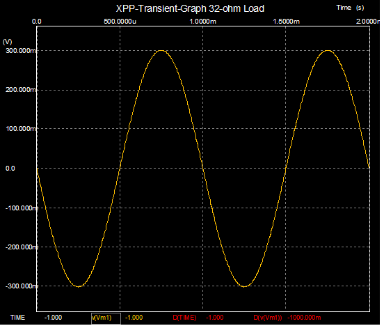
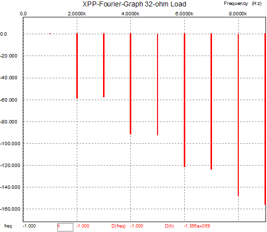
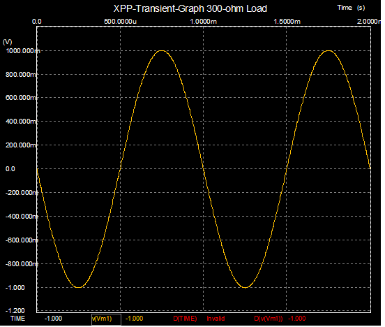
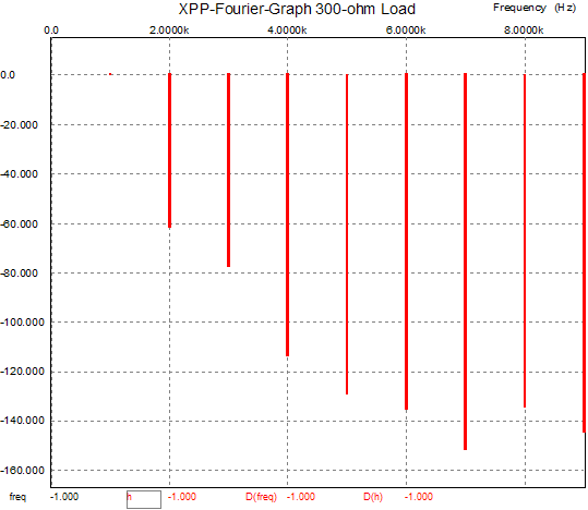
Now at the other extreme—infinity—the voltage gain at the output equals roughly mu/2 and top output sees roughly zero input signal, much like the Gomes circuit. And much like the Gomes circuit, the circuit loses its push pull operation, as it reverts to single ended mode. (Actually, without a load, push pull is a fairly meaningless concept anyway.) Let’s look at some real loads, starting with 1 ohms (yes, 1 ohms), 32 ohms, 300 ohms, and ending with 300k.
Mercy, 1 ohm is brutal for solid-state amplifiers; yet notice how low the distortion is (about 0.1%), a testament to high-quality balanced operation.
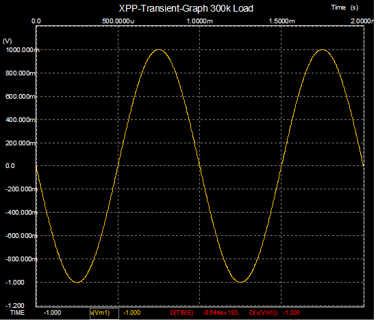
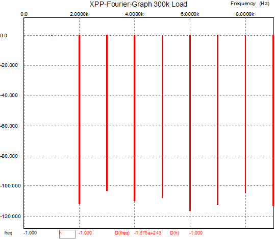
Notice that 32 and 300 ohms are easily handled within sane limits. By the way, The output stage can use bypassed cathode resistors and even different tubes between input and out stage, which can even further the performance into these low-impedance loads. 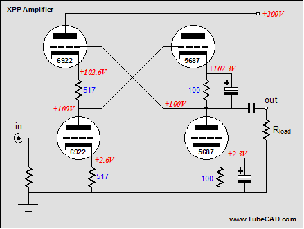 At the high-impedance extreme of 300k, however, the tables turn on the XPP amplifier and the Gomes-TCJ circuit produces a cleaner output.
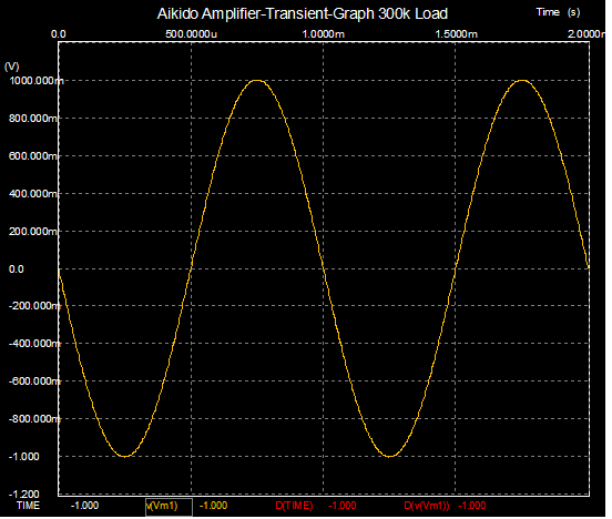
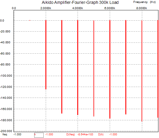
How well does the comparable Aikido amplifier perform? Look below for the answer.
So have we arrived at the perfect push-pull tube amplifier with the XPP? No. But that will have to wait until another time (soon, don't worry). //JRB |
TCJ My-Stock DB TCJ My-Stock DB helps you know just what you have, what it looks like, where it is, what it will be used for, and what it's worth. TCJ My-Stock DB helps you to keep track of your heap of electronic parts. More details. Version 2 Improvements *User definable Download or CD ROM |
|||
| www.tubecad.com Copyright © 1999-2004 GlassWare All Rights Reserved |

