| John Broskie's Guide to Tube Circuit Analysis & Design |
30 December 2004
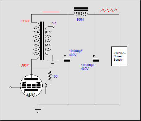
Looking at the fixed version of the “bomb” amplifier, we see a problem. Noise. Here's the paradox: a feedback loop that terminates at the plate will reduce the noise at the plate, but not at the speaker terminals, as all the power supply noise will be superimposed across the output transformer's primary.
The feedback loop can be so subtle that pass under the raised eyebrows of the nervous audiophile; for example, even without using an OpAmp and a two-resistor feedback loop, using a triode in a pentode’s stead. Because the pentode’s plate resistance is so high, it makes a poor voltage divider with the primary’s impedance. On the other hand, a triode’s low plate resistance, which is a form of feedback and being usually half of the primary impedance, does create a deep voltage divider against the primary impedance. In this example, the primary will see 66% of the power supply noise; the triode, the remaining 33%. 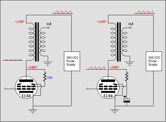
In the case of the OpAmp feeding the output tube, whether it be a triode or a pentode, the primary will see close to 100% of the power supply noise, as the feedback creates an effective plate resistance of close to zero ohms. This noise is treated no differently than music signal would be and is readily passed to the secondary and loudspeaker. (In a push pull amplifier, such a feedback loop would attach at each plate, which means that the noise would cancel, as it would appear as a common-mode signal, which the transformer could not pass.) What can be done? The obvious way is the brute force way: either huge chokes and fat power supply capacitors or a complex high-voltage regulator that bulldoze over the power supply noise. Distrust the obvious.
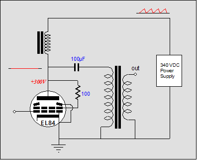
The opposite approach is not to lower the noise at its source, but isolate it: separate the noisy power supply from the primary by placing an inductor in between, as in a parallel-feed amplifier; or use an active constant-current source in between to isolate the noise from the primary.
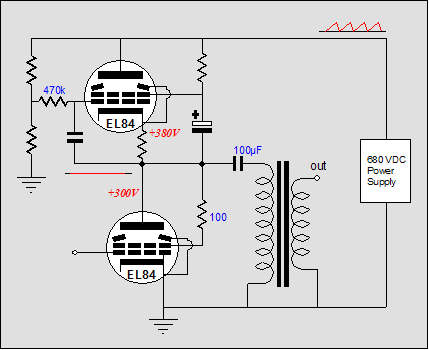
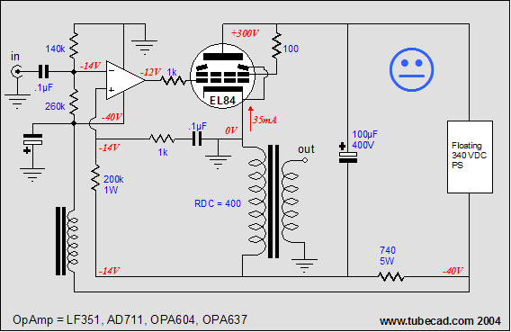
The Aikido approach is to use the power supply’s noise against itself and was outlined in "Lowering the Single Ended Amplifier's Output Noise," wherein a small portion of the noise is injected into the output tube’s cathode, which is then amplified and the noise on the plate equals the noise on the power supply rail, which means that the output transformer’s primary can’t “see” the noise. A different approach altogether might have been offered by Albert Einstein: instead of fighting you biggest problem, make what had been the problem the first principle of your new system. In this case, feedback is referenced to ground, not the power supply, so move the output transformer’s reference to ground as well. In other words, the noisy B+ is allowed to continue to be noisy, but the transformer no longer terminates into it, but ground. No, the amplifier is not going to be run in a cathode follower mode. 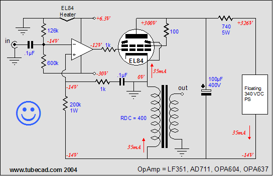 Einstein amplifier Long-time readers will remember how the components in an electronic circuit can be moved around much like beads in a necklace, as long as a few rules are not broken, such expecting electrons to flow from the plate to the cathode. We leapfrog the output transformer over the power supply and it now connects to the output tube’s cathode and the power supply’s negative terminal. The signal ground is located at the cathode and the high-voltage power supply left to float, which means that each channel requires it own high-voltage power supply (both channels can share the low voltage power supplies). The output tube still functions as a grounded-cathode amplifier, amplifying its input signal and inverting that signal at its plate. Except this time, the power supply relays the plate’s movement to the output transformer. If a pair of scope probes are attached across the output transformer’s primary, we see power supply terminated end of the primary swing hundreds of volts both positively and negatively. Yes, positively. The output tube behaves identically to how it would before, exhibiting the same plate resistance and amplification factor. The output transformer behaves identically to before, presenting the same reflected impedance and swinging positively and negatively with varying current flow. 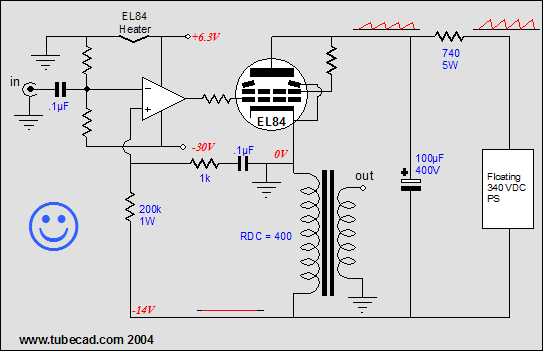
If no external feedback loop is used, the output tube and output transformer primary would still see the same ratios of power supply noise: 33% across the triode and 66% across the primary. But since an external feedback loop is attached at the end of the primary, the triode will see 100% of the noise; the primary, 0%. If the primary does not see the power supply noise, then the loudspeaker will not either. Note the +6.3-volt power supply rail. This rail is used to supply the output tube’s heater and the OpAmp’s positive power supply connection, which will allow the OpAmp’s output to swing a few volts more positive than the output tube’s grid (the OpAmp can handle it and there is no coupling capacitor to become adversely charged). The –30V power supply rail provides the OpAmp a negative power supply rail. The OpAmp is capacitor coupled to the outside world, which prevents DC and ultra-low frequencies from upsetting the output stage. Additionally, the DC input voltage, as defined by the two-resistor voltage divider, sets the idle current through the output stage (autobias on the cheap), as this same voltage will be superimposed across the output transformer’s primary DC resistance. In other words, a different output transformer or a different idle current will require a different DC input voltage. Note the how the OpAmp’s inputs have been swapped: the non-inverting input receives the feedback signal and the inverting input receives the input signal. What has happened is that the output tube has inverted the input signal, so the composite amplifier is still non-inverting.
Einstein on the cheap
This time the same power supply that feeds the output stage feeds the OpAmp as well. And the OpAmp’s positive power supply connection is ground, which means that this version of the amplifier will put out less watts than the previous version, as the grid can never be driven positive. A choke decouples the power supply at AC frequencies, but lets DC current pass, allowing the OpAmp’s power supply capacitor to charge. The smoothing resistor (it could just as easily be a choke with the same DCR) has been moved to negative leg of the power supply, thereby creating a faux negative power supply. Faux? If the output tube does not conduct—for example the output tube is cold or its filament is open—there will be no negative power supply voltage; or if the output tube conducts too much—for example someone plugs the wrong tube in the socket—there will be too much voltage. (A safety zener—say, 36 volts—across the OpAmp would be a good idea.) A separate power transformer would not suffer from these problems. Thus, I cannot recommend this circuit without first doing some on-hands testing. Still, the circuit is tempting. (No doubt that some are so niggardly that they will substitute the choke with a plain resistor. The danger here is that this resistor is effectively shunting the output transformer’s primary and may end up dissipating a good deal of heat. A classic example of being so cheap that you end paying more.)//JRB Lost e-mail A second helping of crumbs 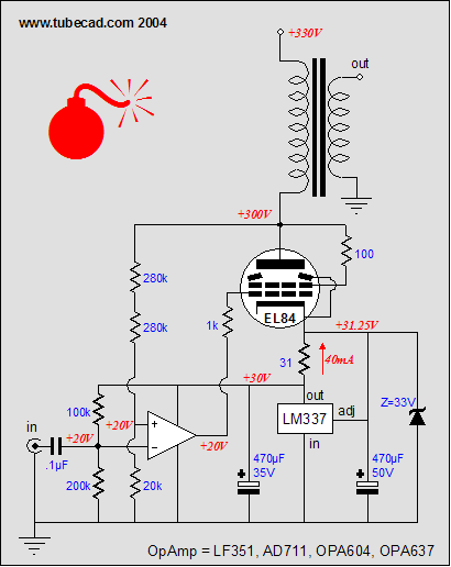
The first problem can be eliminated by doing away with one of the feedback loops. 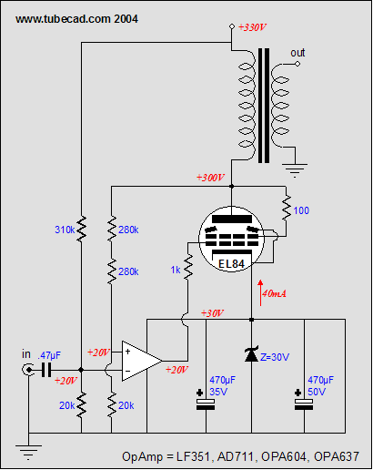
Above we see the modifications: no LM337, an added zener, and a repositioned voltage divider resistor string. In this setup, the OpAmp sets the bias by monitoring the voltage drop across the primary’s DC resistance against the output of a voltage divider. If the tube conducts excessively, the plate will be forced less positive, which in turn will force the OpAmp’s positive input negative relative to its inverting input, which will force the OpAmp’s output more negative, lessening the tube’s conduction. The zener provides a fixed cathode voltage for the OpAmp to work against. The voltage divider resistor string that sets the DC reference voltage for the OpAmp’s inverting input no longer attaches to the OpAmp’s power supply, but to the main B+ voltage. No doubt that a few readers are troubled by the reliance on the B+ to set the bias voltage, as this voltage is only fixed when it fed from a regulated power supply. True enough. But if you perform the math, the error isn’t too bad for +/- 5% B+ voltage variations. Still, better tolerance is easily obtained; just add a voltage reference. 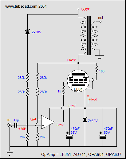
In the above schematic, the voltage reference has taken the form of a zener diode place in series with the resistor-based voltage divider. Now, even if the B+ climbs or falls, the current through the output tube remains constant. (Actually, a zener is probably a poor choice, as the zener will most likely require a greater current conduction to break at the specified voltage than is provided by the voltage divider resistors; low-current IC voltage references are a better choice.) Fixed bias and the LM337 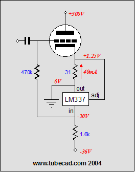
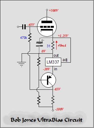
The LM337’s output is grounded. Yes, grounded. (If this makes head swirl, then pretend that this schematic holds no ground connection whatsoever; just power supplies, but no ground. Ground is more of a state of mind than many are willing to imagine. Imagine a friend hands you a black box with two terminals on it. you measure the voltage across the terminals and declare that the black box holds a positive 100-volts power supply. Your friend takes away the box with a look that say that he doesn't trust you with sharp scissors and says, "No, its a negative 100-volt power supply. Who's right? Which terminal do you want to call ground?) The sense 31-ohm resistor bridges the output tube’s cathode and ground. The LM337 adjustment pin reads the voltage drop across this resistor and alters it conduction in response. If the tube conducts too much, the adjustment pin is forced positive, which will reduce the LM337 conduction, dropping the grid’s bias voltage, as the voltage drop across the 1600-ohm resistor collapses. Conversely, if the tube conducts too little, the adjustment pin is forced negative, which will increase the LM337 conduction, raising the grid’s bias voltage, as the voltage drop across the 1600-ohm resistor increases. Note the discrepancy between the current flowing through the output tube (40mA) and the LM337 (10mA). This means that the LM337’s own idle current need match the output tube’s, which in turn means that we are not forced to use TO-220 packaged LM337. The LM337 is also available in a small SOT-223 package (and the TO-39). This circuit will only work over a limited voltage range, as its 37 volt limit isn’t that much to work with. The LM337HV extends this limit to 50 volts, but this is still too low for use with a 300B or 845. The solution is to add a cascode transistor to the LM337’s input. 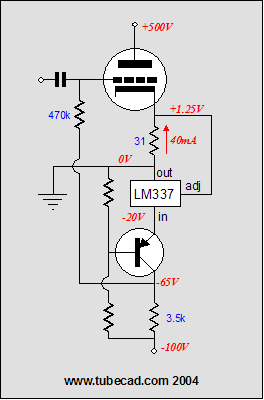
With MJE350 PNP transistor in place, the circuit can be used down to a –300 volts.By the way, the sense resistor can be bypassed with a large-valued capacitor. I almost didn’t mention this because I am tickled by readers emailing me radically improved and reworked circuits that have appeared in the Tube CAD Journal. (A few times these improved circuits have come from different websites than here.) Often the topology is unchanged, but different valued parts are used or even only different brands are specified. Usually, the original schematic has been done over in PhotoShop, so that the reader’s name can be superimposed (always in a fancy typeface). For example:
Next time //JRB 28 December 2004 A feast of crumbs
Tube CAD Journal / april_may2001 / page 6 It feels odd to quote myself, but I like that last sentence too much not to quote it. Hunting for crumbs is a great pursuit, searching through non-audio electronic articles, probing solid-state data manuals, snooping in industrial trade journals. When you look at a schematic, a topology, an electronic part, try to see beyond its intended use; in fact, try to see how it wasn’t intended to be used. For example, ON Semiconductor’s MBR40250, a 250-V Schottky rectifier, has intended uses in computer power supplies, automotive body electronics, and energy-recovery circuits in plasma TV sets, not tube amplifiers. Just ask On Semi’s electrical engineers. Yet, why not? The MBR40250 silicon power rectifier exhibits a 250-volt blocking voltage and can pass 45A of current and it virtually eliminates reverse-recovery oscillations (much like a tube rectifier), making it an ideal choice for a tube OTL amplifier’s power supply (or, if placed in series, with a 1Meg resistor placed in parallel with each diode, a transformer-coupled tube amplifier). Because this device intended use is not tube audio, the price is a reasonable 30 cents each, whereas had its intended use been tube amplifier power supplies, it would cost closer to $30 each. (I’m sure that high-end-audio mail-order boutiques can correct this situation, “The more you pay, the better it sounds,” is their motto after all.) Of course, the 250-volt specification was an obvious invitation to look further. As a good rule, whenever you see high-voltages, think tube. On the other hand, what about the solid-state devices that aren’t so robust in the face of high-voltages? For example, the lowly LM337 negative voltage regulator, whose input-to-output voltage limit is a measly 37 volts, how could it be used in a tube amplifier? Well, its brother, the LM317, is often used in high-voltage regulator, where it is nested in its low-voltage compartment, regulating nonetheless. Or, at the other end of a tube, it is used as a constant-current source that takes the place of the cathode resistor in setting the tube’s idle current. (By the way, this trick only works in a true honest-to-God class-A amplifier, whether push pull or single ended.) 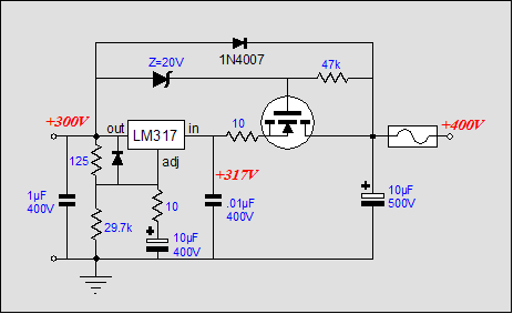
Thus, we should at least be able to use the negative voltage regulator in a high-voltage negative regulator, as the supporting high-voltage PNP transistors and N-channel MOSFETs are available. And there is no reason that the LM337 couldn’t also be configured as a constant-current source and also used in place of a cathode resistor. 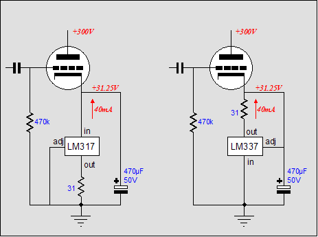
Which constant-current source would be better, the LM317 or the LM337? A perfect tossup is my guess. Except in one circuit, a hybrid amplifier that uses an OpAmp to directly drive an output tube. The constant-current source sets the output tube’s cathode at the right voltage to allow the constant-current source’s preset current to flow. Additionally, the output tube’s cathode voltage can also be used to provide an OpAmp its positive power supply. 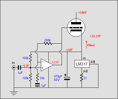
Note that the OpAmp’s own current draw is outside the constant-current source’s purview. In practical terms, this is not that big a deal, as the OpAmp draws only few milliamperes of current. Still, why not include the OpAmp’s current in the constant-current source’s tally? With an LM317-based constant-current source, we do not attach the OpAmp’s negative power supply connection to ground, but to the top of the sense resistor. Now all the current flowing through the resistor will be fed back into the regulator and its conduction will be adjusted accordingly. The LM317’s output will still offer the same low output impedance and low noise that it would in its intended voltage regulator application, so the OpAmp’s negative power supply connection should be happy (in most OpAmps, the negative power supply connection holds a much poorer PSRR than its positive connection, so extra care is needed here). The OpAmp’s positive power supply connection, on the other hand, connects directly to output tube’s cathode and is shunted by the large-valued bypass capacitor. 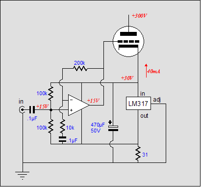
Using the LM377 turns everything on its head. Its input is grounded and it output feeds the output tube through the sense resistor and it also provides the OpAmp with its positive power supply connection. The OpAmp’s current conduction is added to the tube’s through the sense resistor, which means that the LM337 will include this current in its count. If the LM337’s adjust pin isn’t bypassed to ground, then the regulator’s output will not be as stiff as otherwise. So here is the complete circuit. 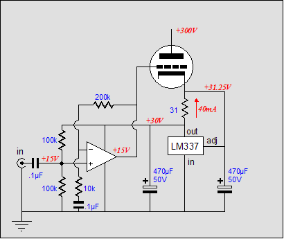
The OpAmp’s input is referenced to half of its power supply voltage; and as the feedback loop is terminated into a decoupling capacitor, its output will also be referenced to this same voltage. In other words, as the constant-current source moves the cathode voltage up and down to set the desired current flow, the OpAmp’s output follows by half. For example, if the cathode voltage climbs by 10 volts the OpAmp’s output climbs by 5 volts. Eventually, the stasis—the counterpoise, the equilibrium—point is reached, where cathode-to-plate, grid-to-cathode voltages work to establish the desired idle current. Consequently, the cathode-to-ground voltage will be roughly twice the voltage that it would be with only a cathode resistor, which works against us, as no triode is perfectly linear, all requiring more negative swing than positive swing to achieve equal plate-voltage swings. For example, a triode with grid bias voltage of –20 volts only requires +20 volts of swing to reach the positive-grid-voltage limit, whereas it might need –30 volts of swing to be completely cutoff. Thus, in this circuit, where the cathode rests at +40V and its grid at +20V, the triode can never be cutoff. Of course, this would only occur when the OpAmp's feedback loop encompasses the output tube, whereas in all the previous schematics, the feedback loop only corrals the OpAmp.  In the schematic above, we see the OpAmp configured to swing more negative than positive, as it output is referenced to 66% of the power supply voltage available to it. Note the DC feedback loop. Here is where I think a tug of war could begin; the OpAmp will work to establish the same voltage at both its inputs and the LM337 will work to keep a constant predefined current flowing through the output tube; unfortunately, these two aims may be mutually exclusive. Additionally, this amplifier will reduce the noise at the plate, but not at the speaker terminals. No noise at the plate means that all the power supply noise will be superimposed across the output transformer's primary, which in turn will be relayed to the secondary. 
So, here is a simple hybrid amplifier that runs in single ended mode, but there’s no reason that it couldn’t be used in a push pull amplifier, if matched tubes were used, or if two LM337s were used. Why is this circuit better than a LM317-based version? I feel much more comfortable with the OpAmp's negative power supply connection being made at ground, rather than some pseudo ground. //JRB |
TCJ Push-Pull Calculator TCJ PPC Version 2 Improvements Rebuilt simulation engine *User definable
Download or CD ROM For more information, please
visit our Web site : To purchase, please visit our Yahoo Store:
nig-gard-ly (nigrd-le) adj. 1. Grudging and petty in giving or spending. See Synonyms at stingy. 2. Meanly small; scanty or meager: left the waiter a niggardly tip.--nig'gard-li-ness n. --nig'gard-ly adv. Excerpted from American Heritage Talking Dictionary
| |||
| www.tubecad.com Copyright © 1999-2004 GlassWare All Rights Reserved |


