| John Broskie's Guide to Tube Circuit Analysis & Design |
01 January 2005 The Perfect Line Amplifier
Carlo, thanks for the kind words. But I don’t think I am half as bold as you, as I would be terrified to use the word “perfect.” Yes, you are right: the Aikido approach works to undo what is already wrong and it would offer little in a perfect world, much as the real Aikido would be needless. (Yes, I know that there is a great deal more to Aikido than just self defense, but the "great deal more" would already be included if it were a truly perfect world; think about it.) As for chess, I love it, but I haven’t played a game in 20 years. (I believe my style was closer to reckless and sneaky, but maybe I flatter myself. I was much moved by Paul Morphy’s games) Now, for the good and bad news. 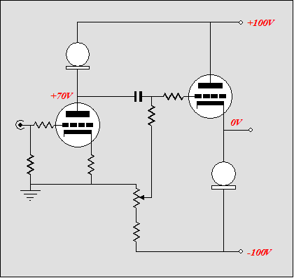
Above a quick overview of Carlo’s Perfect Amplifier. The constant-current source loads the input triode, isolating the triode from the positive power supply rail’s noise. It also allows the greatest gain from the triode (close to the amplification factor). And it also keeps the distortion low, although not nonexistent. (Draw a horizontal line across a set of plate curve and mark the distance between grid-line intersections. If there were no distortion, then the distances would be identical; they aren’t.) At the output, the constant-current source that loads the cathode follower does wonderful things for this buffer. It allows the greatest gain from the cathode follower and it buffers the cathode follower from the negative power supply noise. However, it does not lower the cathode follower’s output impedance or make the cathode follower perfectly noise free. But first, let’s look at his complete schematic. (I took the liberty of adding grid-stopper resistors. If you think that grid-stopper resistors are a bad idea, try driving your car without shock absorbers, as they perform an analogous function: they add resistance to a dangerously reactive mix.) 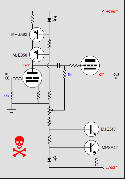 The Perfect line amplifier Carlo is not afraid of solid-state parts, which I think is healthy. (Imagine a biblical scholar who refused to learn Greek, relying exclusively on Hebrew to understand original New Testament manuscripts. Well, refusing to study solid-state—or vacuum state electronics—would be equally foolish.) The LEDs work as cheap voltage references (real voltage references—IC precision voltage references—are only a few dimes more, so why not use them?). All the transistors are high-voltage (the inner transistors are protected from the high-voltages by the MJE340 and MJE350, so why not use low-voltage transistors instead, particularly low-voltage, low noise transistors?) The negative power supply matches the positive in voltage magnitude. The output is DC coupled and its offset is adjusted by the potentiometer. All in all, not a bad line amplifier by any means (certainly better than many commercial efforts). Now for the but…but is it really coupling-capacitor free, when a coupling capacitor bridges the input stage to the cathode follower? If the amplifier which follows is a tube design, this might pose no problems, but what happens when a solid-state amplifier is used? For example, at startup, when the cathodes are cold, the solid-state constant-current sources are not dormant, but instantly excited to conduct their preset current. Thus, the solid-state amplifier will see its input swing –100 volts (never a good idea). The cathode follower will see its grid swing +100volts, while its cathode sits at –100 volts (quite a voltage differential for any tube). The same holds true for when a tube is jiggled in its socket. Do not use this circuit unless you know that it cannot harm your system; In other words, not recommended without a coupling capacitor at the output. Having said that, the goals are still admirable. A completely-tube-filled design would look like this: 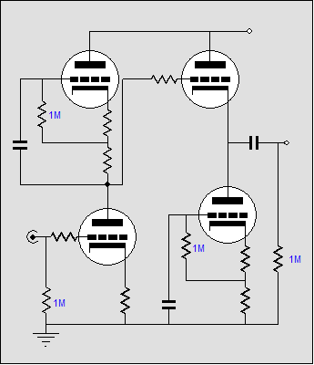
The coupling capacitor has been restored to the output and triodes are used to create constant-current sources and the bipolar power supply has been reduced to a single polarity. This version is much safer than the original, but it also suffers from a power supply noise failing that a little Aikido can remedy. Imagine that the first constant-current source works perfectly and the input stage is perfectly noise free. Now, this means that the cathode follower’s triode sees at its grid zero noise, effectively ground, but its plate sees the full magnitude of power supply noise. So what is the result at its cathode? Zero noise? Some noise? The answer is that the constant-current source only made the situation slightly worse, as the noise at the cathode can now approach its theoretical maximum of 1/mu. Think about it: the plate voltage varies, but the current flow is constant, as is the ground voltage. So the only thing that can vary (and something must vary) is the cathode voltage, as a triode can not conduct the same current with two sets of plate voltages and a constant ground voltage. Thus, the need for a little Aikido. If the constant-current source that loads the cathode follower were to break its consistency enough to allow a little power supply noise, then the cathode could remain noise free, as its current conduction would no longer be constant. Ironic, isn’t it? The first step is to specify a bottommost cathode resistor equal to the triode’s rp. The next step is to “ground” the cathode follower’s constant-current source at the B+ connection, not ground. What we have created here is a grounded-cathode amplifier that has a gain of 1/mu when loaded by the top tube’s cathode impedance. Because the grounded-cathode amplifier inverts its input signal, the weakly amplified noise will cancel the weak amount of noise the top triode passes. 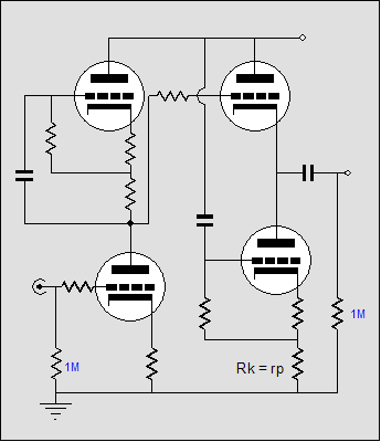 "Wait a minute," you say, "I use a regulated power supply, so I don’t care about power supply noise; I just want super linearity." Well, if that’s the case, why not use a "super" simpler circuit: 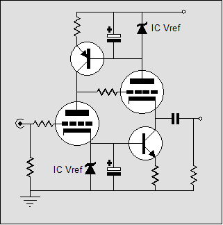
Once again two constant-current sources are employed and at the same places, but only two transistors are needed and high-quality voltage references are used instead of LEDs, which have always given me pause—I am not sure that I trust them. Current mirror rescue 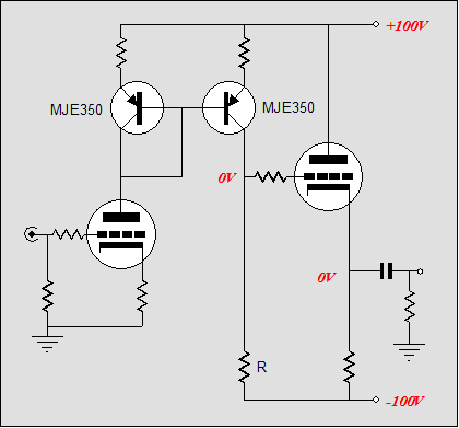
The gain is roughly equal to what the triode would yield in a cascode circuit. With a bypassed cathode resistor, roughly, gm·R. Without a bypassed cathode resistor, roughly, mu·R/([mu + 1]Rk + rp). The cathode follower takes its input signal from this resistor’s connection to the current mirror and it buffers it from the output. The cathode follower is not constant-current source loaded; purposely. First of all, I believe that constant-current source loading of a cathode follower is grossly oversold. Sure it looks great on paper, but in the real world where low-impedances abound, it makes little difference. For example, a 300-ohm headphone element in parallel with infinity is still 300 ohms, a tough load for any triode-based cathode follower. But notice the noise relationships in this topology. The input tube sees almost all of the power supply noise at its plate, which induces a current variation roughly equal to Vnoise/(rp + [mu + 1]Rk). This current variation is then transferred to the current mirror’s output and develops a noise voltage equal to R·Vnoise/(rp + [mu + 1]Rk). But the connection to resistor R was not noise free to start with, as negative power supply rail holds a noise signal equal –Vnoise. Thus, the final noise signal found at the top of resistor R is equal to R·Vnoise/(rp + [mu + 1]Rk) – Vnoise. Well, if we specify that R equal rp + (mu + 1)Rk, then the equation reduces to R·Vnoise/R – Vnoise and then to Vnoise – Vnoise. Yes, zero. Ah, math...you have to love it. So we have a noise-free input for the cathode follower, what about the noise leaving the cathode follower? Since the cathode follower is loaded by a cathode resistor equal to its rp, both the triode and resistor experience the same noise current, which means that at their junction +Vnoise cancels with –Vnoise. Once again, zero. The problem here is that since both triode and resistor see the same voltage differential, the triode’s grid and cathode must share the same DC voltage, not a good idea. The solution requires one extra resistor. 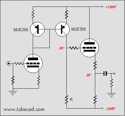 Perfect Reflection line amplifier The added cathode resistor combined with the triode define an effective “resistor” equal to rp + (mu + 1). Now, we specify that the bottom cathode resistor equal this value as well. This way we retain the noise null and lighten the idle current through the cathode follower. Additionally, the amplifier out does not directly attach at the cathode. This is a secret way of improving the sound, as the top cathode resistor buffers the cathode from the output (imagine 20 feet of high-capacitance cable) and linearizes the cathode follower’s output. Conclusion PS R = rp + (mu + 1)Rk + Rcm, Where Rcm equals the current mirror’s resistor into which the input triode terminates.
//JRB |
TCJ Push-Pull Calculator TCJ PPC Version 2 Improvements Rebuilt simulation engine *User definable
Download or CD ROM For more information, please
visit our Web site : | |||
| www.tubecad.com Copyright © 1999-2005 GlassWare All Rights Reserved |


