| John Broskie's Guide to Tube Circuit Analysis & Design |
07 July 2005 A wrong turn The output stage has the advantage of working into an inductively-coupled load, so it can swing its cathode(s) far bellow ground, as if there were a negative power supply equal to the positive power supply; the driver stage tube is seldom so lucky. For example, in this example, the output stage’s B+ voltage might only be 150V. Now, do we fit 222V of peak-to-peak voltage swing into a 150-volt B+? We don’t...not without cheating.
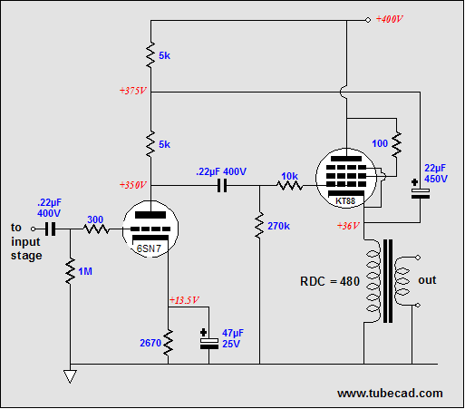 Bootstrapped driver stage In the circuit above, we see a bootstrapped, single-ended, cathode-follower output stage. Note the shared B+ voltage and the small driver stage plate resistor value (5K). Now a 6SN7-based grounded-cathode amplifier loaded with a 5k plate resistor and a unbypassed cathode resistor could only realize a gain of about 2 or less; yet when used in a bootstrapped configuration, the gain can easily equal something close to the tube’s mu. (The closer the cathode follower’s gain is to unity, the greater the driver tube’s plate resistance magnification, but the less cathode follower action obtained from the output stage; for example, if the cathode follower’s gain were 1, then its grid would effectively be “grounded” to its cathode.) I was about to go further into the inner workings of bootstrapping when I remembered that I had already covered the topic in the Tube CAD Journal, at least twice. To read more on bootstrapping, follow this link . Read this page and the page after. (I’ll be immodest here: I wish I had the Tube CAD Journal to read 25 years ago when I began to study tube electronics in earnest. It would have saved me hundreds of hours in musty library stacks, peering into old books and journals; and countless hours soldering together circuits, testing, evaluating, and burning a finger or two.)
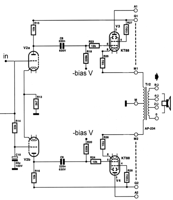
The May 2001 issue of the great international electronic magazine, Elektor Electronics, held an interesting amplifier output stage design, which is shown above. There is so much that I like about the article—it refers to the circltron topology that the amplifier uses as the "parallel push-pull," for example—that I feel bad about sending a large torpedo it way. The claim made is that this version of the circltron/parallel amplifier uses output tube in a cathode-follower configuration; it doesn't. The dashed lines represent well-filtered, floating power supplies. These power supplies ensure that the pentode's screens are tightly locked to the swinging cathodes and they also directly connect to the driver stages plate resistors, which undoes all the cathode follower attributes, as the bootstrapping relays any disturbance at the output cathodes right back to the output grind in phase, not anti-phase.

Legitimate short cuts A step-up transformer can perform a miracle of sorts: it magnifies its input signal by its winding ratio; 1Vac goes in and 10Vac—or even 100Vac—comes out. But as the transformer also strictly abides by the laws of physics, we still have to pay for our lunch. True, the input signal was increased by the winding ratio, but the input impedance presented at the transformer’s primary is also decreased by the square of the winding ratio. Thus the output tube’s grid resistor’s value is reflected to the transformer’s input as a much more severe load, as it is effectively decreased by the square of the winding ratio, so a 400k grid resistor will be reflected as a 1k resistor by a 20:1 step-up transformer. Of course, if the secondary is directly attached to the cathode follower’s grid without a grid resistor shunting the winding, this concern does not apply—until the grid is driven positively relative to the cathode follower’s cathode that is! (Once the grid becomes positive relative to the cathode, the grid and cathode define a forward-biased diode and goes from not conducting to conducting heavily.)
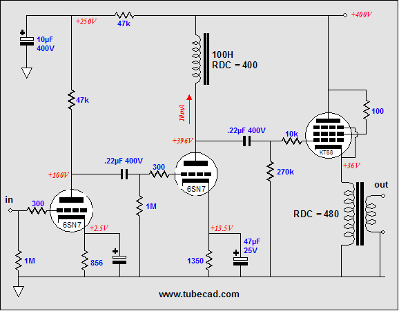
Transformer-coupled In addition, the input capacitance that the secondary connects to is effectively reflected to the transformer’s primary by the same square of the winding ratio, so 15pf can equal 150pf or 1,500pf at the primary. Luckily, a cathode-follower output stage exhibits a much lower input capacitance than does a grounded-cathode amplifier output stage, as the cathode follows the grid and the grid-to-plate capacitance is not magnified by inverted gain at the plate. Furthermore, adding an interstage transformer to amplifier makes adding a global negative feedback loop at least difficult, if not dangerous, due to the phase shifts that a transformer would introduce. In other words, a step-up transformer could be a godsend, but real-world impurities may prove too burdensome to overcome. In other words, no free lunches whatsoever. Choke/inductor plate loads allow us to retain the single B+ voltage for both driver stage and output stage. Just as the output stage has the advantage of working into an inductively-coupled load, which allows it to swing negatively well bellow ground potential, the inductor plate load allows the driver stage to swing well beyond the B+ voltage. An ideal inductor would displace none of the B+ voltage; real inductors made from thin wire do displace some of the available voltage. Still, the DCR seldom exceeds 1k, so not that much voltage will be lost to due to the driver stage’s idle current against the inductor’s DCR. The inductor must have enough inductance to allow low frequencies to be amplified by the driver tube. The formula is:
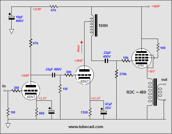
Choke load A component that falls in between a transformer and a simple choke is the tapped choke. This inductor holds at least one tapping point in the coil and it allows the choke to provide a step-up function, much like the step-up transformer does.
Center-tapped choke load Next time //JRB
|
SE Amp CAD
SE Amp CAD helps you design SE Amp CAD™ is the Windows program that helps you design, understand and modify single-ended amplifier output stages. With SE Amp CAD, you can point and click to a new output stage configuration in minutes. SE Amp CAD is a virtual workbench for single-ended output stage design. True Curves™ is the name of the mathematical model used in SE Amp CAD. True Curves knows how a 300B or an 845 really bends: how the plate current varies with changes in grid to cathode voltage versus changes in plate voltages. More Details... Windows 95/98/Me/NT/2000/XP
For more information, please visit our Web site : To purchase, please visit Antique Electronic Sales' website:
Help keep the
Tube CAD Journal going strong Only $12.95 to start designing tube-based crossovers and much more...
The Tube CAD Journal's first companion program, TCJ Filter Design lets you design a filter or crossover (passive, solid-state or tube) without having to check out thick textbooks from the library and without having to breakout the scientific calculator. This program's goal is to provide a quick and easy display not only of the frequency response, but also of the resistor and capacitor values for a passive and active filters and crossovers. TCJ Filter Design is easy to use, but not lightweight, holding over 60 different filter topologies and up to four filter alignments: While the program’s main concern is active filters, solid-state and tube, it also does passive filters. In fact, it can be used to calculate passive crossovers for use with speakers by entering 8 ohms as the terminating resistance. Tube crossovers are a major part of this program; both buffered and un-buffered tube based filters along with mono-polar and bipolar power supply topologies are covered. . Downloadable version (4 Megabytes file). Download or CD ROM
|
|||


| www.tubecad.com Copyright © 1999-2005 GlassWare All Rights Reserved |