29 June 2005
Click on image to see the full image
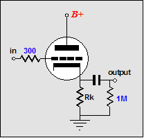
Here’s the usual cathode-follower-power-amplifier design thought process: since—as compared to a grounded-cathode amplifier—the cathode follower offers a much lower output impedance (Zo), the output transformer’s winding ratio can be equally reduced, allowing the use of 500-ohm primary instead of the 5,000-ohm primary needed for a grounded-cathode amplifier. Right? Absolutely dead wrong! It is as wrong as believing that holding a magnifying glass over a gold coin will not only make the coin appear larger, but weigh more as well. Just as the coin’s actual size and weight remain unaltered, the triode’s transconductance (gm), amplification factor (mu), and plate resistance (rp) remain unaltered, as nothing inside the tube’s envelope has changed.
The topology changes, not the tube’s internal functioning. The tube has no idea what circuit topology it finds itself in; it only knows plate, grid, and cathode voltages and currents. If we want to change the tube’s rp or gm, we have to break the glass envelope’s seal and alter the tube’s internal structure.
So what value primary impedance is best for a push-pull or single-ended cathode-follower-based power amplifier? The answer: use the same (I repeat, the exact same) impedance that you would use had the transformer connected to the plates in a grounded-cathode amplifier. Cathode-follower operation does not change the IV (the current/voltage) dynamics that the tube must undergo nor does it artificially lower the tube’s intrinsic rp.
The conceptual problem is born out of a confusion between rp and Zo.
Plate resistance is not the same as output impedance, just as a coin’s weight is not the same as the pressure per square inch it exerts on the table upon which it is resting. (Imagine the gold coin laying flat and then balanced on edge; on edge, the coin could easily exert a hundredfold greater pressure per square inch on the table; yet its weight remains unchanged.) This equality stipulation drives solder-slingers crazy, as they want to use a low-winding-ratio output transformer with a cathode-follower-configured output stage.
Now I understand why someone would want to use a lower-winding-ratio output transformer. With all the necessary conditions obtaining, it is very good idea, as, in general, the higher the winding ratio, the worse the transformer. (I once picked up a few beautifully-made transformers at an electronic surplus store for a buck each. They held a 1.414 to 1 winding ratio and I thought I would use them for a medium-high-voltage power supply [230Vdc]...until I tested one, that is. I almost fell out of my chair; this little beauty passed the sharpest, cleanest 10kHz square wave I have seen from any transformer—and I have tested hundreds. So good, in fact, that I was convinced that I had attached the scopes probe to the transformer’s primary and not its secondary; I had not.) Since cathode-follower operation won't artificially lower the rp, we must use a low rp tube if we want to use a low-winding-ratio output transformer. The 6AS7 and 6C33 come to mind.
Finding an output transformer with a low winding ratio is not easy, however, for either push pull or single ended use. I believe that Tango used to make a transformer for use with multiple 6BX7s and the One Electron UBT-1 single-ended output transformer offers a 1600-ohm primary, but these are the exceptions. I am sure with persistence and Google many more could be found. Failing that, you could have a transformer custom wound. (I would like to see a transformer with a winding ratio of three to one, hence an impedance ratio of nine to one; which, in terms of 8-ohm loads, implies a reflected plate-to-plate impedance of 72 ohms.) Nonetheless, the cathode follower is not a sufficient, in itself, means of employing a low-winding–ratio output transformer, as it cannot lower the tube’s rp. For example, when designing a simple, capacitor coupled, cathode follower (with a 6SN7, for example), we do not burden the tube with a 800-ohm cathode resistor (twice cathode follower’s effective output impedance), even though such a resistor value would seem to follow the 2rp rule, rather we use a value something like 10-30k. Had we specified a 800-ohm cathode resistor, the cathode follower would grossly distort and produce a meager potential output voltage swing. On the other hand, the 10k cathode resistor would allow the cathode follower to swing much larger and produce much cleaner voltage swings.
Wait a minute. The cathode resistor is not the same as the load impedance, which might just equal 800 ohms. True enough, but the cathode follower circuit still does not provide any free lunches. Unlike the political realm, wherein free lunches can be had at other people’s expense, in electronic circuits, the laws of physics are strictly enforced. Given the same load impedance, the same B+ voltage, the same idle current and the same triode, the cathode follower and grounded-cathode amplifier put out the same amount of power into the same load impedance. The key word in the last sentence was "power." In spite of prevailing opinion, the cathode follower circuit is not simply a clever way to wring more power out of a tube. The B+ voltage, the load impedance, and the tube’s rp strictly limit the maximum power output of tube into the load, regardless of whether the load attaches at the cathode or the plate.
In fact, the cathode follower’s usual function is to provide a low-distortion, low output impedance for high-impedance loads—high in relation to the output impedance. If cathode followers are said to sound bad, it is because they are so often grossly misused. For example, 12AX7-based cathode followers that are expected to drive 600-ohm loads, because of the 600-ohm output impedance the 12AX7 produces in a cathode follower. Trust me: a 12AX7-based cathode follower sounds dreadful driving a 600-ohm load beyond a few tenths of a volt—and I mean only one or two tenths of a volt, not three or four tenths. The 12AX7 does not suffer from too high an output impedance, but too high an rp, which in turn implies too low an idle current.
For example, a 6DJ8—placed in a cathode follower circuit—has a lower Zo than a 6AS7 in the same circuit (80 ohms vs. 93 ohms); however, the 6AS7 will put out much more power, as its ten-times-lower rp allows ten times more current to flow into the same load with the same B+ (assuming a low impedance load, say 32 ohms). Ten times more current into a load means a lot more than ten times more watts into the load; one hundred times more, in fact. If the current is doubled into a load impedance, then the voltage across that impedance must also be doubled, so the wattage must be quadrupled; tens times the current equals tens times the voltage, thus ten time ten times the original wattage.
Let’s do the math with the 6DJ8 and 6AS7 and the 32-ohm load and a B+ of 100 volts. The peak output current swing a triode can muster without entering positive grid voltage is:
Ipk = B+/(rp + Rload)
In the case of the 6DJ8,
0.0395A = 100V/(2500 + 32).
In the case of the 6AS7,
0.32A = 100V/(280 + 32).
With a peak current swing of 0.0395A, a peak 1.264V swing voltage develops across the 32-ohm load. With a peak current swing of 0.32A, a peak 10.24V swing voltage develops across the 32-ohm load. The first figure realizes 25mW into 32 ohms; the second, 1.63W into the same load; a ratio of 65 to 1. (If the 6AS7’s rp were 221 ohms, we would have gotten the 100-to-1 ratio.)
Therefore, if you want to design a single-ended cathode-follower amplifier, use a primary impedance of 4-6k for the 45, 2.5-3k for the 2A3, 3-5k for the 300B and triode-connected EL34 and 6550, and 10k for the 211, as the IV dynamics are the same no matter where the primary attaches.
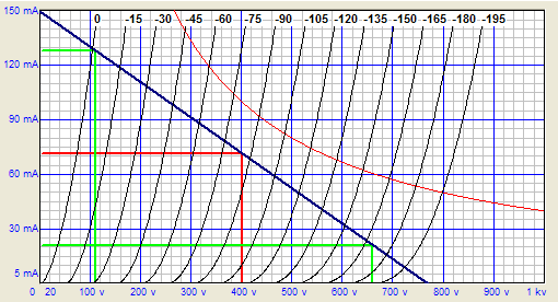
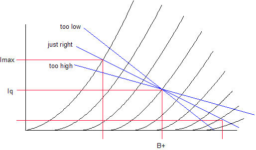
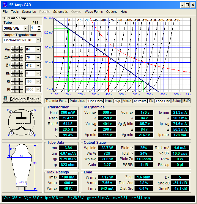
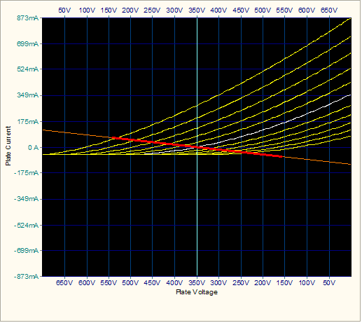
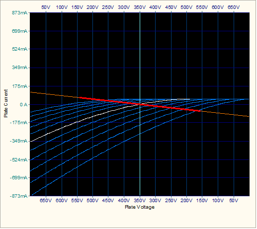
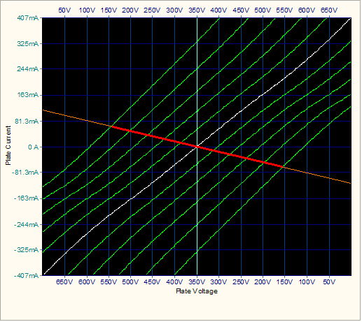
If you want to design a single-ended, cathode-follower, fixed-bias amplifier, get hold of the output tube’s plate curves. Next, draw a vertical line at the B+ voltage and then specify how much dissipation you are willing to subject the output tube to (75% is a good stating point). Now, locate where along the B+ voltage line the dissipation equals your target. For example, if the tube has a dissipation limit of 40W and we specify 30W of dissipation and the B+ voltage is 300V, then the 30W will occur at 100mA, so we draw a horizontal line intersecting this point and we draw another horizontal line at 10% of the idle current value, in this case, 10mA. This last line marks the floor we do not want the output tube to extend into, as that’s where the distortion is the greatest. Next we highlight, if only in our minds, the 0-volts grid line and the 10% idle current line. The primary impedance load line must fall equally between these two lines. Thus, we pivot a ruler at the intersection of the B+ voltage and idle current and we rotate the ruler (a symmetrical ruler works best) until an equal distance exists between the segment that connects the 0-volt grid line and the ruler’s pivot point and the segment that connects the pivot point to the 10% idle current line. Once the right slope is found, we must work out the implied load line, which equals voltage over current. Thus, we first subtract the plate voltage at the intersection of the 0-volt grid line with the load line from the B+ voltage; next, we subtract the idle current from the current at the intersection of the 0-volt grid line with the load line. For example, we might get 300V – 100V = 200V and 150mA – 100mA, which would equal a load impedance of 200V / 50mA = 4,000 ohms.
So was that it? No, not really, as it is only a good first approximation, as we must subtract the voltage lost due to the output transformer primary’s DCR. Assuming a DCR of 300 ohms and an idle current of 100mA, we lose 30 volts of B+ voltage, which means that we can increase the idle current a tad. In other words, we embark upon an iterative process that shouldn’t take too long to get to a workable solution. What if we want a cathode-biased, single-ended amplifier? Then we will need to account for the lost voltage due to the added cathode resistor, which becomes difficult in the cathode-follower single-ended amplifier, as the primary DCR is part of the bias circuit. (I would use SE Amp CAD and set the DCR to zero ohms. Then, when finished, I would subtract the DCR from the cathode resistor value.)
What if we want a cathode-biased, push-pull amplifier? I would use TCJ Push-Pull Calculator and be done with it, as the two sets plate curves need to meld into a single set of curves, which is almost impossible without a computer or infinite patience.
We will cover driving the cathode-follower output stage.
//JRB
|
|
|
|
Kit User Guide PDFs
Click image to download


Support the Tube CAD Journal
&
get an extremely powerful push-pull tube-amplifier simulator for
Only $19
TCJ Push-Pull Calculator
Version 2
Click on images to see enlargements


TCJ PPC Version 2 Improvements
Rebuilt simulation engine
Create reports as PDFs*
More Graphs 2D/3D*
Help system added
Target idle current feature
Redesigned array creation
Transformer primary & secondary
RDC inclusion
Save user-defined transformer
definitions
Enhanced result display
Added array result grid
*User definable
TCJ Push-Pull Calculator has but a single purpose: to evaluate tube-based output stages by simulating eight topologies’ (five OTL and three transformer-coupled) actual performance with a specified tube, power supply and bias voltage, and load impedance. The accuracy of the simulation depends on the accuracy of the tube models used and the tube math model is the same True Curves™ model used in GlassWare's SE Amp CAD and Live Curves programs, which is far more accurate than the usual SPICE tube model.
Download or CD ROM
Windows 95/98/Me/NT/2000/XP
To purchase, please visit our Yahoo Store:
|


