| John Broskie's Guide to Tube Circuit Analysis & Design |
22 June 2005
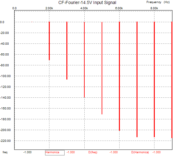
Cathode-Follower Power Amplifiers Circlotron delayed (I didn't know just how misunderstood this application of the cathode follower was until I came out with the TCJ Push-Pull Calculator program, which includes the transformer-coupled, push-pull, cathode-follower-based power amplifier in its library of eight tube power amplifier topologies. After a handful of e-mails that all held the same misunderstanding, I knew that I needed to provide a tune-up article/blog.) Cathode-follower power amplifiers Before answering this question, let's review the assumptions. First of all, how much less distortion does a cathode follower produce than a grounded-cathode amplifier? Using a 6SN7, a cathode load of 20k, and an input signal of 1V into a cathode follower yields the following graph:
Note the absence of distortion harmonics beyond the third harmonic and the low distortion (less than 0.01% THD). Now, let’s see what a 6SN7 in a grounded-cathode amplifier, a plate load of 20k, and an input signal of 1V generates:
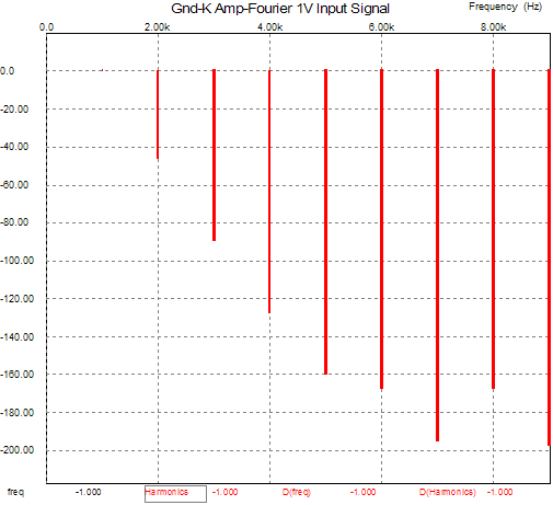
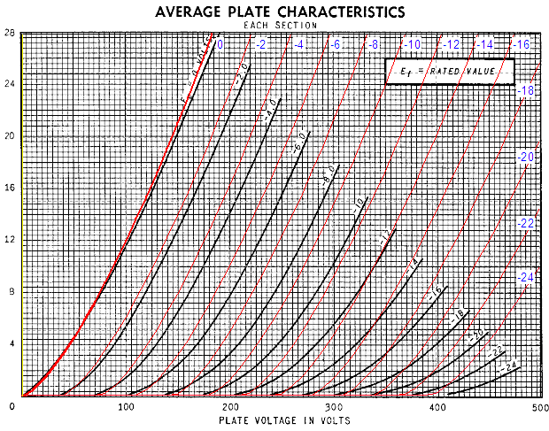
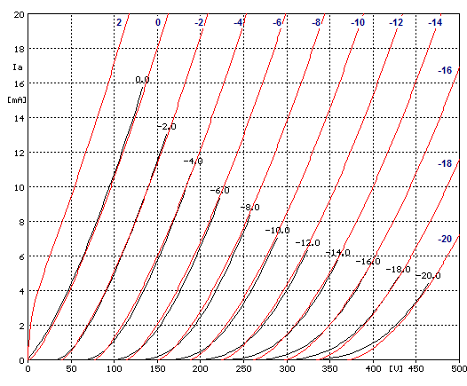
Not nearly as good. The total distortion is closer to 0.5% and the harmonics extend beyond the third into the eighth. Is this possible? Or, put differently, What’s wrong with this picture? The results are born of SPICE simulation, which depends on the SPICE model’s accuracy to yield accurate results. In this case, however, a more accurate model may reveal more distortion from the cathode follower, but the grounded-cathode amplifier’s distortion would probably go up in the same proportion, so the relative results would remain constant. Still, it is fun to compare simulation to reality. Below is a curve trace of the Duncan SPICE model of the 6SN7 overlaid on a GE tube manual set of plate curves.
Well, at least the 0-grid voltage line is close. But how good is the tube manual's graph? My guess is that most graphs in tube manuals are not born of a curve tracer's output, but only the result of a handful of spot point data lists and a French curve and a steady hand. Consider this: most tube manual graphs existed before Tektronix came out with their famous 570 curve tracer (mid 1950s); what was used in its stead other than a high-voltage power supply, an ammeter, pad and pencil? Below is a curve trace of the Duncan SPICE model of the 6SN7 overlaid on a Sofia curve tracer plot:
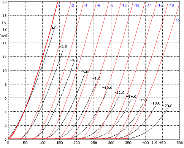
No so good. Notice the bottom of the curve tracer plots, where it bends severely. To be fair, I should put my own tube math model (True Curves tm) to the same test. Below is the True Curves model of the 6SN7 overlaid on a Sofia curve tracer plot:
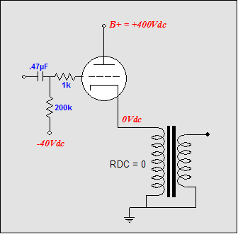
Not as bent on the bottom as the real thing, but quite accurate above 2mA (for this sample 6SN7, other 6SN7s will, of course, trace a different set of plate curves). So why not use my math model instead of the SPICE model? That’s what I do in my own software, but the math model does not work in SPICE (I know, as I spent a year trying). One of the reasons is the 32-bit floats that SPICE is limited to, opposed to the 64-bit floats I have access to; another reason is the large exponents overwhelming the SPICE engine without the benefit of programmatic error handling and exponent limiting. Beyond the limitations of the SPICE model, a fundamental error in comparing these two circuits is at hand. We are comparing the results of an equal input signal, not an equal output voltage swing. The grounded-cathode amplifier produces 13.5 volts of swing with the 1-volt input signal, whereas the cathode follower produces only 0.93 volts of swing. If we boost the input signal that the cathode follower sees to 14.5 volts, then the cathode follower’s output will match the grounded-cathode amplifier’s voltage swing and experience the same current swings.
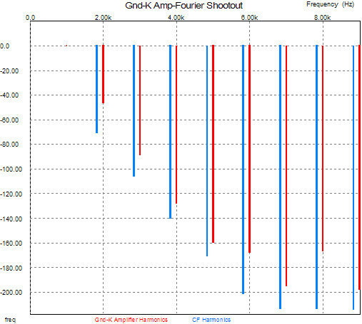
Now, still using the flawed SPICE model, the distortion climbs closer to the grounded-cathode amplifier’s, but still much better, as is shown in the graph below.
As for output impedance, there isn't much debate. The cathode follower's output impedance equals: whereas the grounded-cathode amplifier's output impedance equals: Thus, the higher the mu and the lower the rp, the lower the output impedance. This means that a 300B-based SE amplifier would sport an output impedance of only 0.4 ohm, not the usual 2 ohms, with a KT88, with its higher mu, even greater reductions in output impedance can be expected. Miller-effect capacitance is not added to the cathode follower's input, as the plate remains fixed and the cathode follows the grid. This means that with the same driver stage, we would expect the CF-based amplifier to extend at least mu times further than the comparable grounded-cathode amplifier. The problems that CF power amplifiers face
In addition, the driver stage must be able to swing to at least –380 volts to drive the cathode negatively to –300 volts. (A global feedback loop would force the driver stage swing even more deeply into the negative to turn the output tube off, as triodes are harder to turn off than they are to turn on.) And +/-340 volts equals a power supply voltage that must at least equal 680 volts, with perfect output devices; and, in actual practice, at least 800 volts, with real driver tubes, such as the 6BX7, 6SN7, 12B4, and 5687. Yet, the output stage’s power supply could be as low as 400 volts. 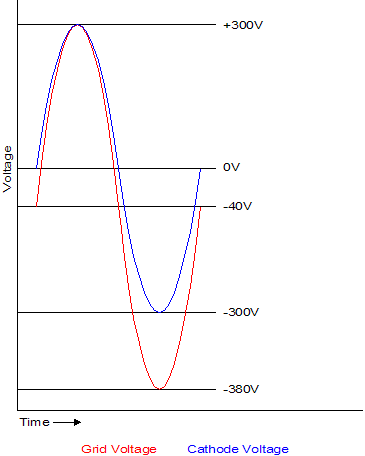
Implicit in the large voltage swings is high gain. In the previous example, a gain of at least 340 is needed to take a 1-volt input signal to the driver stage’s 340 volts of swing. (If a passive line stage is used, even more gain will be needed.) More gain means more tubes: at least two front-end tubes in a feedback-free amplifier and most likely three tubes in a feedback-filled amplifier. For example, assuming a driver stage gain of 10 and no feedback, the input stage would have to provide at least a gain of 34, which a 12AX7 or 12AT7 could easily provide, but a 6922 or 6N1P couldn’t. If the amplifier employs a feedback ratio of 20 dB, then the input stage gain must equal at least 340, which even the most robust cascode stage could hardly generate. The total input and driver gain would equal 3,400 in this last example. Cascode? SRPP? Constant-current source loading? No, the answer is more input tubes in series. High gain and many tubes in series usually means high distortion. Paradoxically and unexpectedly, the output stage could easily have a lower distortion figure than the front end of the amplifier. A lesser hurdle is supplying the output tube with its own heater power supply, which must be referenced to the cathode, not ground. This means that all the tubes in the amplifier cannot share the heater winding on the power transformer. The easy workaround is to use either a power transformer with multiple heater windings or add a separate heater transformer. Next time //JRB
|
Help keep the
The Tube CAD Journal's first companion program, TCJ Filter Design lets you design a filter or crossover (passive, solid-state or tube) without having to check out thick textbooks from the library and without having to breakout the scientific calculator. This program's goal is to provide a quick and easy display not only of the frequency response, but also of the resistor and capacitor values for a passive and active filters and crossovers. TCJ Filter Design is easy to use, but not lightweight, holding over 60 different filter topologies and up to four filter alignments: While the program’s main concern is active filters, solid-state and tube, it also does passive filters. In fact, it can be used to calculate passive crossovers for use with speakers by entering 8 ohms as the terminating resistance. Click on the image below to see the full screen capture.
Tube crossovers are a major part of this program; both buffered and un-buffered tube based filters along with mono-polar and bipolar power supply topologies are covered. Available on a CD-ROM and a downloadable version (4 Megabytes). Download or CD ROM
|
|||


| www.tubecad.com Copyright © 1999-2005 GlassWare All Rights Reserved |