| John Broskie's Guide to Tube Circuit Analysis & Design |
17 April 2006 
Detour ahead Well, this topic must be postponed until the next blog entry, as I have to perform some conceptual housekeeping before littering your mind with any more new interesting projects. (Besides, I am not done drawing the headphone amplifier schematics and I am waiting for some more feedback from a few readers who blazed ahead and our using the Aikido as headphone amplifiers.)
Getting R15 & R16 straight
Resistor ratio = 1/mu + ½ I have received enough e-mail from Paul to know that he can teach me plenty about carefully measuring an amplifier, so it was unlikely that he had incorrectly measured the noise. In fact, he had tested the resistor values with a VOM and he had tried other ratios and other 6SN7s, but always the two 100k resistors worked best. I was about to pull out my hair, when I asked if the bottom resistor was the larger. He replied that it wasn’t, but also noted that that wasn’t what I had posted here—and he included a screen capture of the Aikido schematic. He was right: I had posted the wrong order in several of the Aikido schematics. (I have since corrected the erroneous schematics.) 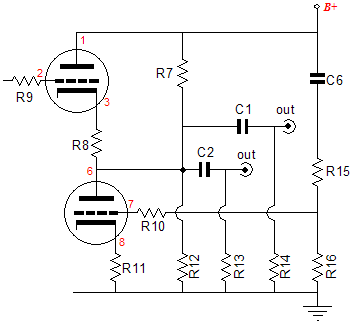
What a headache. First, there was the same error in the PCB user guide PDFs, now this. How did it happen? Easy. First, I used a different formula than the one I posted, which a reader had provided; my formula yields the same ratio, but does not lead to division-by-zero errors with a 6AS7 triode (I think like a programmer): R15 = R16(mu – 2)/(mu + 2). For example, a 6AS7’s mu of 2 renders R15 = 0, rather than R16 equals infinity. So I am accustomed to changing resistor R15’s (the top resistor's) value and leaving R16 (The Bottom resistor) fixed at 100k in my own design work and experiments. But I figured it was best to use the other formula on this website. Unfortunately, it proved harder to do than I expected. In other words, feel free to use either formula, but do so consistently. Second, I cut and paste a great deal when drawing schematics, which means that an error can spread from one schematic to the next. Yet even after I thought I had fixed the PDFs, I was told that nothing had changed; the PDFs still read the same. Madness. I used my FTP program to open the PDFs at the website and, indeed, they had been updated. However, when I downloaded them, they hadn’t been. What was going on? It turns out that you have to press the reload button on your web browser, otherwise it just keeps loading the old PDF from its cache on your hard drive, not the revised PDF off this website. R15 and R16 Values for common triode types The table below uses a fixed 100k R16 resistor value and show R15 in exact and the closest standard 1% resistor values.
*Tube cannot be used with the 9-pin Aikido PCB and is only listed for reference.
Can both outputs (from coupling capacitors C1 and C2) be used at once, with each one driving its own amplifier? Yes, indeed. Why would anyone want to do such a thing? I can think of several possibilities. For example, a bi-amped system could be easily assembled, using one of the coupling capacitors to limit the low-frequency energy to small satellite loudspeakers, while the other feeds the bass amplifier that powers the subwoofers. Thus, small and expensive coupling capacitors can be used for the high-frequency outputs and large—but cheap—coupling capacitors can be used for the low-frequency outputs. Or one set of coupling capacitors could be used for a dedicated, solid-state, low-input-impedance headphone amplifier, while the other is used for a high-impedance tube power amplifier. I am sure that many of you will find other uses for the two coupling capacitors. Here's a question I have gotten twice, which means there 200 hundred readers wondering the same thing: How do I wire up a rotary switch for switching between the two coupling capacitors? We need a four-pole, three-position switch and some hookup wire. All four coupling capacitors attach to the input contacts and the two channels of output can receive either coupling capacitors C1’s or C2’s or both capacitors’ outputs. The drawing below shows the knob on the faceplate and the rotary switch from behind. (The switch is shown on the "C1 + C2" position.) 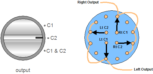
Aikido amplifier background information: Next time //JRB
|
Only $12.95
Download or CD ROM www.glass-ware.com
|
|||||||||||||||||||||||||||||||||||||||||||||||||||||||||||||||||||||||||||||||||||||||||||||||||||||||||||||||||||||||||||||||||||||||||||||||||||||||||||||||||||||||||||||||||||||||||||||||||||||||||||||||||||||||||||||||


| www.tubecad.com Copyright © 1999-2006 GlassWare All Rights Reserved |