| John Broskie's Guide to Tube Circuit Analysis & Design |
At first, I planned to use two power supplies for the 6GM8-based Aikido: one for the heaters and one for the Aikido amplifier’s B+. Thus, I would need to supply 24 volts and 6.3 volts or 12.6 volts. This bothered me, as all four heaters in series would require 25.2 volts, which would also work as the B+ voltage, so why not one power supply? Surely, one power supply voltage is easier to accomplish than two. However, the 9-pin Aikido PCB only allows the four tubes’ heaters to be wired in parallel or two heaters in series, but not all heaters in series. Or does it? After staring at the heater schematic, I saw how the PCB could be used without any cutting of traces, although a few import details must be observed. Below is the heater schematic. 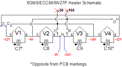
Note that two of the heaters are already in series, so all that remains is to place these two strings in series. Jumper J1 does just that. However, we can no longer use the two heater power supply pads, but jumper J4’s pads instead to connect the 25.2-volt power supply. VERY IMPORTANT: two of the heater shunting capacitors must be reversed from the printed orientation. Capacitors, C7 and C10, must be flipped around, positive and negative leads reversed, so that the electrolytic capacitors are not damaged by seeing a reverse voltage. Remember, only 1 volt of reversed voltage is enough to damage an electrolytic capacitor, possibly rupturing and releasing noxious chemicals (in fact, tantalum capacitors can go off like little hand grenades when their polarity is reversed). 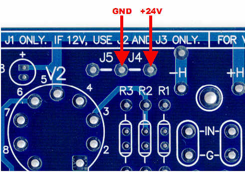
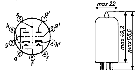
Now that the heaters can work off the B+ voltage, the rest of the circuit can be fleshed out. First of all, I plan on using a 24-volt power supply, not a 25.2 volt one. Why? Two reasons: I own four 24-volt power supplies, two regulated linear and two switching. Second, the tubes will last slightly longer with 6 volts than with 6.3 volts across their heaters. A 24-volt B+ voltage means that each triode will have 12 volts (minus the voltage drop across its cathode resistor) to play with. Looking at the plate curve below reveals that a cathode resistor value between 160 to 200 ohms will set an idle current of 2mA. The value I plan on using is 187 ohms (again because I have them). 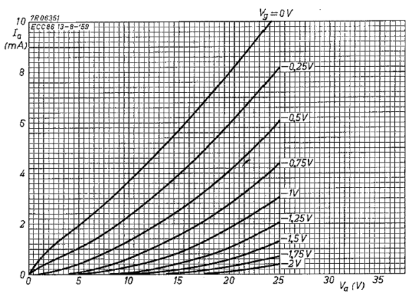
The total gain of a 6GM8-based Aikido line amplifier will be close to +15dB, which should work handsomely in most systems. The output impedance will be less than 600 ohms. I cannot measure the distortion, as I have not assembled my unit yet. However, those who have used the 6GM8 before tell me that it a clean-sounding triode. All that remains is to calculate the Aikido power-supply noise voltage divider resistor values. The formula is R16 = R15[(mu + 2)/(mu -2)]. Thus, with an ECC86 and resistor R15 equals 100k, R16 equals 129k. 
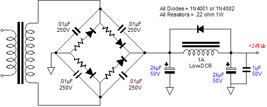
24-Volt power supplies A simple non-regulated power supply can be built from an 18Vac power transformer, a diode bridge, and a few capacitors. It just might sound good as well. 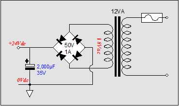
However, I would prefer to be a bit more nervous. For although the Aikido boasts an excellent PSSR figure, I don’t want to tax it any more than necessary. Even if the power supply isn’t regulated, a few small tricks will deliver big sonic gains. For example, chokes perform wonders in stripping away power supply blemishes. I have found that just about any choke, of any inductance or DCR, is better than not using a choke in a power supply, even if that power supply terminates in a voltage regulator. One inductor and one extra capacitor added to the simple power supply will make a big difference in performance. In fact, a bigger difference than might be expect in normal tube gear. Why? Inductors work best working into a dead short. As the terminating resistance increases, the inductor loses effectiveness, just the opposite of a capacitor. Fortunately, for this inductor-based power supply, the heater string represents a 76-ohm resistive load, whereas the tubes alone represent a 3k load. Therefore, what started out as a liability (having to power the heater string) becomes an advantage to the inductor-filled power supply. 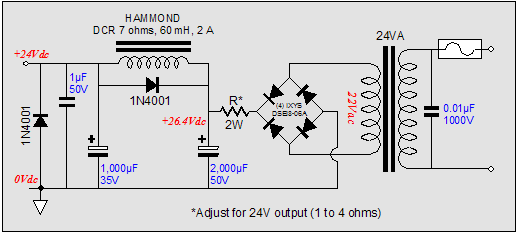
Because the current draw is so high, the inductor’s DCR becomes an import circuit element, as the voltage drop across the inductor will steal a much larger percentage of the available B+ voltage than it would in the normal tube line amplifier, which might only draw 20mA. In other words, a low DCR is critical. I would place a DCR limit of 10 ohms, as a 10-ohm DCR will displace 3.4V, which will demand a 22Vac transformer winding to yield 24V for the B+. Which rectifiers should be used? I recommend ultra-fast rectifiers, such as the popular HEXFREDs or the unpopular Schottky diodes. (Developed by International Rectifier, in the 1970s, “FRED” stands for Fast Recovery Epitaxial Diode, thus the trade name “HEXFRED.” Today, manufacturers include Harris, International Rectifier, IXYS and others. Tube folk do not know about Schottky diodes because, until recently, it was not possible to buy a high-voltage Schottky diode. But these fast rectifiers also make for cleaner power supplies.) IXYS DSEI8-06A rectifiers cost less than a dollar, so no one will have to take out a loan. The worse choice, other than a WE275 rectifier (too much current draw), is the cheap and ubiquitous 1N4001. This rectifier works well in many non-audio applications, but it spurs too much switching-induced noise into an audio power supply. Still I know that many readers will opt for them, as they already own several dozen. If you insist on using them, then build the circuit below. Paradoxically, the added capacitors actually slow the diodes, while the 0.22-ohm resistors help soften the transitions between conduction and non-conduction. And the choke filters away the ripple.
Regulated 24 volts 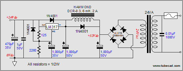 Next time //JRB
PCB update Right now, I am working on getting some chassis built for the Aikido and a suitable power supply for it as well. I have a good source for front panels and knobs, but not for the simple clamshell enclosure I envision. The power supply is an interesting challenge, as it must be worthy of (and as clever and as elegant as) the Aikido amplifier. For a lot more information on the boards, follow the link to the TCJ hardware page of the GlassWare Yahoo! store.
Small Aikido schematic page typo (9-Pin outputs) V1, V4
(9-Pin inputs) V2, V3
(Octal outputs) V1, V4
(Octal inputs) V2, V3
Still, who knows? Maybe a 12BH7 driving a 12AT7 sounds great in your system. The whole point behind the Aikido PCBs is flexibility.
Major Aikido schematic page typo To download an updated PDF of the instruction sheets for Rev 2 PCBs, click below: Octal Aikido PCB PDF Octal vs 9-pin tubes Now, let me skate onto the thinner ice. I really like the sound of old octals over newer octals, say octals from the early 1940s over the late 1950s. Why? My guess is that in the old days they had to use a fatter grid wire and eventually they figured out how to use thinner wire, which allowed making smaller tubes, but to the disadvantage of the tube’s sound. Why would fat grid wire be better? Theoretically, it wouldn’t, but, practically, it might prove much less microphonic. I would like to build a test setup that amplified the internal vibrations of a tube under test, much as if it were a microphone. Then we could plainly hear the tube’s mechanical overlay.
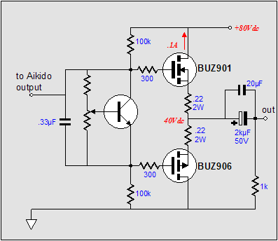
Aikido hybrid power amplifiers
I have been asked which is better: MOSFET or transistor output stages. My answer is that I prefer MOSFETs, not just for their more forgiving sound, but because they are much more reliable and easier to bias correctly. Unfortunately, they are much more expensive and harder to get (well, at least the best lateral MOSFETs are). Still, even the best MOSFETs, in the absence of a global feedback loop, are not as clean sounding as the average power tube in a feedback-free amplifier. As soon as I typed the previous sentence, I began to argue against it in my mind. What is missing is the qualifier “typically,” as a single-ended MOSFET amplifier can sound just magical. Unfortunately, it is so easy to become power drunk and design for the maximum voltage output, not the maximum refinement in output. I know, as I have fallen into that trap many times: “…but 30 watts have to sound better than 15 watts.” After all, isn't “more is better” the American national mantra; why else would we have invented the 64-oz cup of soda. In other words, just because it is so easy to get over 200 watts from solid-state devices, be happy if you can make a great-sounding 50-watt hybrid amplifier. Therefore, my advice is to design relatively small; to do it elegantly but sneakily; to experiment wildly; and, most importantly, to begin cheaply. Why cheaply? Even if you have cash to burn, there is something aesthetically repulsive about buying a $2,000 power cord or $1,000 solid-silver binding posts or $700 coupling capacitors for an amplifier that sits on a Bud box (especially for an amplifier that all too often is—in terms of intellectual competency—downright mediocre, if not worse). Like the ridiculously jacked-up pickups that short men like to drive, a smoldering hot credit card betrays a towering inferiority complex. 
Besides, I have seen too many DIYers paint themselves into a corner by being forced to use some disgustingly expensive parts. For example, a reader once wrote to tell me that his preamplifier sounded terrible and could I help. When I saw his schematic, I knew instantly why the sound was off: instead of 1k cathode resistors, he had used 20k. I asked how he had come up with such odd resistor values and his answer was that he had many tantalum resistors, but that was the lowest value he owned, so he used them. Now, I bet of a third of you are thinking,“What a moron,” while another third are thinking,“What’s wrong with that? That’s what I would do.” And the last third are thinking, “Tantalum resistors? Surely, he must mean tantalum capacitors.” Once your project is built and tested, then discern its single greatest failing. Take that information and modify the operating points, then the topology, if need be; finally, upgrade the offending parts as needed. Imagine how full of pride you would be if your $200 line amplifier, with nickel-plated brass RCA jacks, $1 coupling capacitors, and Radio Shack carbon-film resistors beat the pants off your friend’s $2,000 commercially-made line amplifier. On ther other hand, if your line amplifier cost $3,000 to make, then you would have to back off the smug attitude quite a bit.
Bias schematic typo
Well, maybe or maybe not, as the voltage division might not exceed the safe limits of the MOSFETs’ operation. With a transistor output stage, however, I agree wholeheartedly. Below is a safer version. 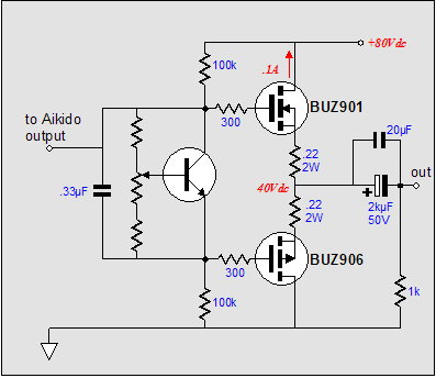 Good design
Aikido hybrid SE transformer-coupled power amplifier 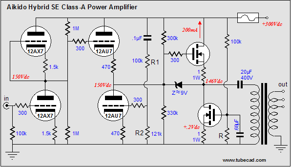
Of course, we have not altogether eliminated the dreaded coupling capacitor, as the output transformer must be capacitor coupled to the MOSFET output. Moreover, the output transformer adds its own limitations into the mix. Still, this circuit might prove to be a great little amplifier. I would start cheap, by using a large-valued Solen or Dayton polypropylene coupling capacitor and a cheap 70V, 15W, audio power distribution transformer. Such an output transformer would reflect about 600 ohms back to the MOSFET output device (this value is a guestimate on my part, based on mathematically working backwards from specs, as Edcor does not specify the transformer’s winding ratio). Alternatively, 600 ohm to 8 ohm output transformers do exist. Assuming that all the idle current can be delivered to the transformer’s primary, the power output would equal 12 watts. Not bad compared to $3,000, 2.5 watts, 2A3-based single-ended amplifiers, but comparatively grim considering that the output stage must dissipate 60 watts at idle. Note that 60 over 12 equals 20% efficiency, not the potential 25%. In order to achieve 15 watts of output, the primary impedance would have to equal 750 ohms and the tubes and MOSFETs would have to be supernaturally perfect. Next time //JRB |
Tube CAD does the hard math for you. This program covers 13 types of tube circuits, each one divided into four variations: 52 circuits in all. Tube CAD calculates the noteworthy results, such as gain, phase, output impedance, low frequency cutoff, PSRR, bias voltage, plate and load resistor heat dissipations. Which tube gives the most gain? Tube CAD's scenario comparison feature shows which tube wins. Windows 95/98/Me/NT/2000/XP
For more information, please visit our Web site : To purchase, please visit Antique Electronic Sales' website: |
|||


| www.tubecad.com Copyright © 1999-2006 GlassWare All Rights Reserved |