| John Broskie's Guide to Tube Circuit Analysis & Design |
27 April 2006
A quick retrospection For example, it is much easier to increase a tube’s conduction than it is to turn its conduction off. This asymmetry works to the ear’s benefit in a single-ended amplifier, as negative-going voltage swings do not result in sharp square-wave edges, rather (because there is no feedback loop) they softly flatten, which the ear much prefers. In other words, the amplifier softly clips in the negative direction. And positive-going voltage swings are not limited to the textbook twice-the-idle-current formula, as the top triode in the Aikido output stage can conduct far beyond that mathematical limit. So what we end up with is an amplifier that fools the ear into thinking it’s much more powerful than in fact it is, as the usual amplifier in-distress artifacts are missing. These grating artifacts are supremely important in judging how loud the reproduction is. The ear associates distortion with volume, so when some clown with the grossly-distorting boom box walks past, we cover our ears to protect them from the seeming high decibels, but, in fact, the sound pressure level is not that high at all, only the distortion is (maybe 70%). In the same vein, when you listen to extremely clean loudspeakers or headphones, you might not realize just how dangerously intense the sound pressure is, as the added distortion is so low. (I was once sitting three feet away from a friend, while listening to his gorgeous full-range electrostatic loudspeakers. After a few minutes, we tried to talk to each other, but we could not hear a word each other spoke, as the loudspeakers were playing so loud—they didn’t sound anywhere near as loud as they were in reality playing.)
A warning 9-Pin Aikido headphone amplifiers Well, since the ECC99 does not beat the 6DJ8 in terms of current conduction, and since its mu is only 22, compared to the 6DJ8’s 33, why bother with it? The answer is found in two specifications listed below: maximum plate voltage and maximum plate dissipation.
Most tube manuals state that the 6DJ8’s plate voltage limit is 130 volts, whereas the ECC99 is 400 volts. (To be honest, I don’t buy the unnaturally low maximum plate voltage for the 6DJ8, which I believe only refers to its use in a cascode circuit, wherein the top triode’s cathode would be 130 volts above ground; for example, I have tested 6DJ8s with 200 volts on the plate, while the triode was used in a grounded-cathode amplifier circuit with no problems. However, in the interest of not being sued: DO NOT USE MORE THAN 130 VOLTS on the plate.) In addition, the 6DJ8’s maximum plate dissipation is only 1.8 watts, whereas the ECC99 is 5 watts. These two important differences will allow for a much more robust output stage with an ECC99 than with 6DJ8. The other clearly interesting triode is the 6H30/6N30. These Russian tubes are amazing. First of all, I like their hefty feel in my hand. Second, they can draw current: a maximum peak pulse current of 2-3A and 111mA with 100 volts on the plate and zero grid bias. Third, they are rated for 10,000 hours of use. This triode seems to be the right choice for a truly overbuilt headphone amplifier.
Input tubes
Aikido low-impedance headphone amplifier (Now, if you and I were in the same room, with me looking you in the eye or over your shoulder, I would let you squirm for at least 30 seconds, maybe longer, as research has revealed that both a pause and a dose of unease actually helps the brain retain information. But since you are reading this, you will have to choose whether to pause here or continue blithely along.) 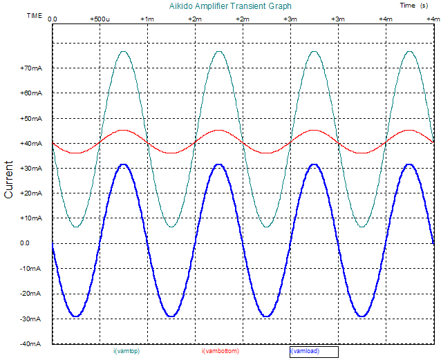
Basically, the bottom half of the Aikido output stage is something of a poor constant-current source, in that it conducts (roughly) the same amount of current no matter what the top triode current swings into the load are. Thus, if the top triode stops conducting altogether, then the bottom triode draws something close to its idle current through the load impedance. On the other hand, if the top triode doubles its conduction, half flows into the load impedance, while the other half, which equals the idle current, flows through the bottom triode. In other words, on positive peaks, the top triode must conduct twice the idle current and the bottom triode continues to conduct at its idle current value; at negative peaks, the top triode ceases to conduct and the bottom triode continues to conduct the idle current value. In the graph above, we the current relationships when a 1-volt sinwave is delivered into a 32-ohm load. Notice how all both top and bottom triodes conduct in phase. There is nothing push-pull about these plots. (By the way, the Aikido does not use an SRPP as the first stage, in spite of what you might have read elsewhere; at no times do the top and bottom input triodes differ in current phase, besides the output is taken at the bottom triode's plate, not the top triode's cathode. A bit pedantic perhaps, but I prefer to err on the side of precise thinking—just to be different, if no other reason. So what topology is the first stage? A symmetrically grounded-cathode amplifier—pure single-ended operation.) 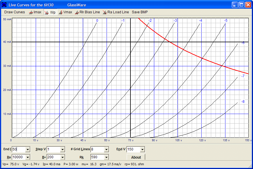
So, the 6DJ8 will not work, but the 6H30/6N30 can easily sustain the require 80mA of peak current flow, without entering positive grid bias or exceeding the plate’s dissipation limit. The penalty we pay is the high 0.825A heater draw and the higher cost of the tube. By the way, I recommend that you download the free Live Curves for the 6H30 program, as it will prove quite helpful in seeing the actual plate curves and the varying mu, rp, and gm that attends different plate voltage and plate currents. Yes, they are, in fact, inconstant constants. (I know that the Live Curves download hasn’t been working but I have fixed that problem by having my hosting company deleting executables.) 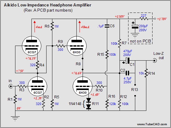
The above schematic reveals some interesting modifications to the stock Aikido amplifier. Note that the output stage holds no cathode resistors, that resistor R8 has been replaced by a piece of wire and R11 has been replaced by two signal diodes in series. Why? Two reasons: to offer the lowest possible output impedance to the headphones and to avoid using any cathode-resistor bypass capacitors. (I would still place a small bypass capacitor across the diode.) Also note how both coupling capacitors, C1 and C2, are wired in parallel. This headphone amplifier presents about a 50-ohm output impedance, which isn’t all that great, but much, much better than many commercial tube-based headphone amplifiers. The (unloaded) gain is almost +20dB with the 6CG7/6FQ7 input tube, which is maybe a bit high, depending on the rest of your system. (The gain can be lowered by using a 12AU7 instead or by loading down the input tube with two 47k resistors, R6 and R5.) The coupling capacitors are a mix of polypropylene and electrolytic. The addition of the electrolytic is unfortunate, but necessary, as the 32-ohm load requires a large-valued capacitor, which would be next to impossible to realize with just film capacitors. A 32-ohm load only requires a 250µF coupling capacitor to ensure a -3dB frequency of 20Hz. The 470µF coupling capacitor serves to extend further the low-frequency cutoff. The 4.7µF coupling capacitor bypasses the large electrolytic 470µF coupling capacitor. In place of a generic (or even obscenely expensive electrolytic), I would try a Rubycon photoflash capacitor, as these capacitors work quite well in this application. (Never use them in a power supply where they will suffer from excessive ripple current; nor ever use them too close a heat source; nor ever apply any voltage in excess of 85% their stated limit.) The power supply is built on top of a 117Vac isolation transformer, which when (solid-state) rectified, yields about 170V. The 227-ohm resistor drops the B+ voltage down to 150 volts and filters away a good deal of power supply noise. A better choice would be an inductor with a DCR of 227 ohms.
Aikido headphone amplifier as an iPod buddy 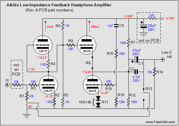 A small amount of PCB hacking is required, but not a lot, as no traces must be cut. Still, this is a project for the more advanced solder slinger. What do these changes buy us? First, a much lower output impedance. Second, less total harmonic distortion and a more stable fixed gain. The downside lies in the harder clipping that the feedback loop introduces and the higher, although low level, harmonics in the distortion spectra. Moreover, relatively low input impedance makes using a normal volume potentiometer or stepped attenuator problematic. And what about the sound? My guess is that hard-rock fans will prefer this sound, that classical-music fans will prefer the feedback free design, and that jazz fans will evenly divide in preference.
Next time 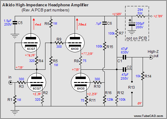 //JRB
|
|
|||||||||||||||||||||||||||||||||||||||||||||||||||||||||||||||||||||||||||||||||||||||||||||||||||||||||||||||||||


| www.tubecad.com Copyright © 1999-2006 GlassWare All Rights Reserved |