| John Broskie's Guide to Tube Circuit Analysis & Design |
7 May 2006
There is so much to cover that I am not sure where to begin. I have always had e-mail problems, but here a new twist: I regularly look in the spam and garbage folders for good e-mail. Since there is over 5,000 a day, I use the search function, with several key words, such as tube, Aikido, transistor, MOSFET, triode, GlassWare... (You would surprised how many porn-spam e-mail contain the word "tube.") This works quite well, except for when Aikido is misspelled, which is amazingly common. Maybe where you live it's "Akido" or "Aikito," but as far as my spam filters are concerned its "AIKIDO."
New PCBs 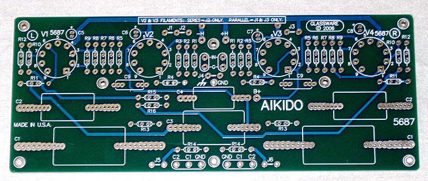
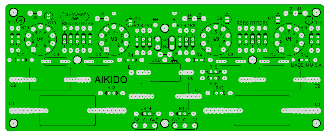
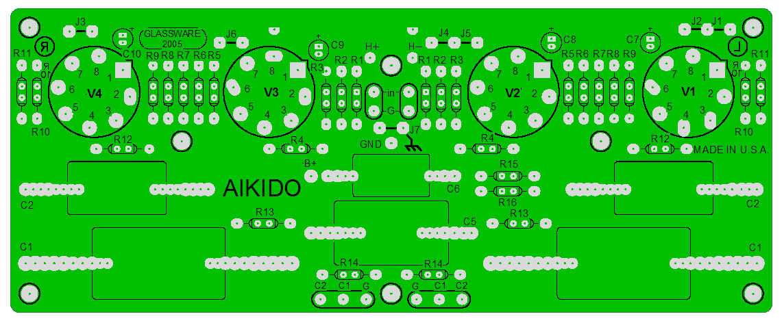
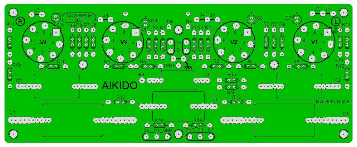
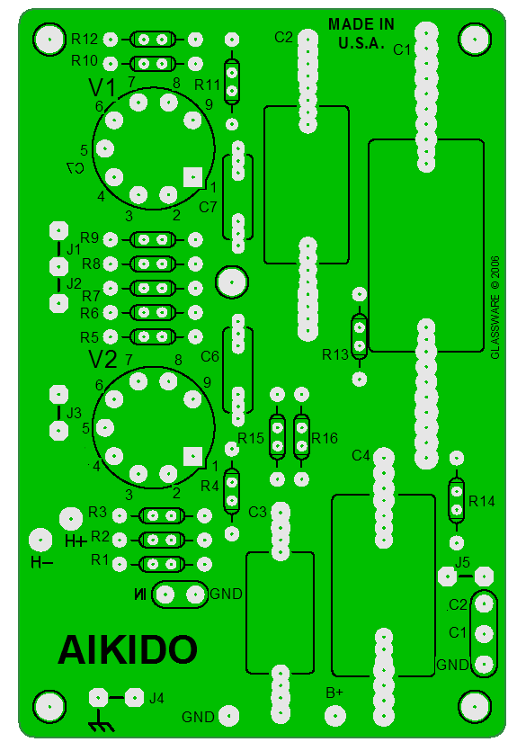
I only had twenty 5687 boards made and I will place 18 of them up for sale at my Yahoo store (I may never order another run, so I want two for myself: one to keep and one to let go when some friend of mine begs me for it). Since so few were made, the cost was much higher than the normal 9-pin boards, so they will sell for a little bit more at $49 each. Not everyone will be interested; but those who are (those who know how good this triode can sound), will be eager to get hold of one of them. [The 5687 PCB is currently sold out. If you are interested, drop me a line; when enough interest builds, i will order a new run of boards.] The other new PCB is a mono Aikido board for 9-pin triodes, such as the 6AQ8, 6BQ7, 6DJ8, 6CG7, 6FQ7, 6GM8, 6H30, 12AT7, 12 AU7, 12AV7, 12AX7, 12BH7, 5751, 6922, ECC99… Why a mono version? Several reasons come to mind: some have returned to the purity of mono hi-fi (half the cost, half the headaches), on the other hand some are running five-channel systems and they require a single Aikido board for the center channel, some need a single microphone amplifier, some cannot use the larger stereo boards in their high-jacked cabinets, some are building monoblock power amplifiers and the stereo boards would be half wasted, and some might be building a stereo amplifier that will not work with the long stereo Aikido PCB, but could accept two smaller PCBs. I am sure there are uses that do not come to my mind. 
The boards hold a power-supply-bypass capacitor and the capacitor and two-resistor voltage divider resistors needed to allow the Aikido amplifier to sidestep much of the power supply noise. These boards also hold two coupling capacitors and offer a jumper to hardwire the two together (for use in a power amplifier, for example). The boards can be used with either a DC or AC (if the heater shunting capacitor is left off the board) power supply (6.3V or 12.6V) for the tubes' heaters, so that 6.3V heater tubes (like the 6FQ7 and 6DJ8) or 12.6V tubes (like the 12AU7 or 12AX7) can be used. Both tubes must share the same heater voltage. For example, 6GC7 for the input tube and a 6H30 for the output tube can be used, although they differ in heater current draw; a 12AX7 and a 6FQ7 could not be used, as they differ in heater voltage; however, a 12AX7 and a 12FQ7 would work. (In theory, a 6.3V and a 12.6V tube could be used in series, if the the two tubes' heaters required the same current draw, but this gets complicated.) Below is the schematic used on the PCB. (Switches S1A and S2A are external to the board.) 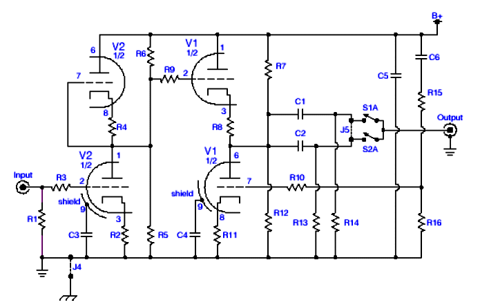
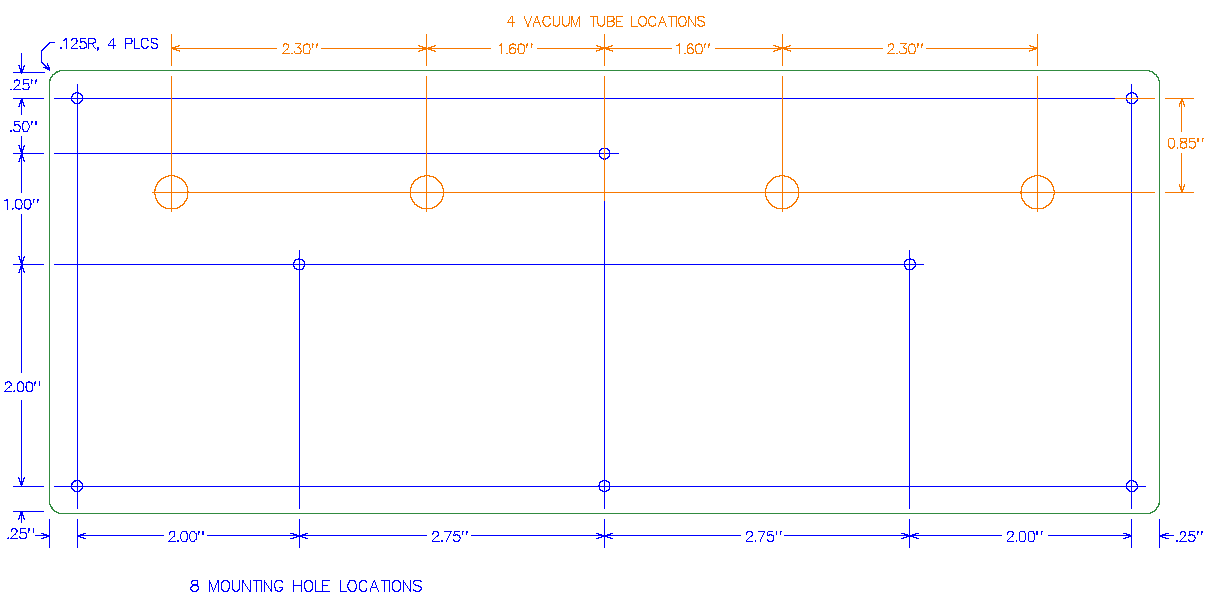
The boards are 4” by 6” and made from the same thick (0.093) PCB stock and heavy copper (2oz) traces as the stereo boards. These boards will sell for $24 each. If you need five of them, then the price is $99 for five of them. (I would love too see and hear five Aikido line amplifiers in one chassis.)
Where is the octal Aikido mono PCB? Octal fans do not panic, next week I should have them in my eager hands.
Tube selection With octals, we have an interesting paradox: the 12SN7 is bettering the 6SN7. Well, at least two readers have told me this. Why? Maybe some factor external to the tubes is tilting the results; for example, let’s say that a 6.3-volt regulator has worse performance than its 12.6-volt brother, which is quite likely, as it must sustain twice the current. or, perhaps, the sample was just too limited. On the other hand, maybe the average 12SN7 is better than the average 6SN7. Two possibilities: the 12SN7s were intended for a more discriminating purchaser, the military for example. Knowing that the tubes would individually tested (and possibly returned!), the tube manufacturers might have held the 12SN7’s production to tighter standards than it did for its more ubiquitous 6-volt cousin. The other possibility is that both tube types left the factory with the same build standard, but with time, and the passing from hand to hand, the good 6SN7s were culled, leaving only the cheesy, mismatched, off-specification 6SN7 to be sold to nervous audiophiles for a high-end premium price. Culled? Let’s say that RCA got a call from an oscilloscope maker that needed very tightly matched triodes inside their 6SN7s for the differential amplifiers inside the scopes, so RCA would pull for them the 10% that were closely matched and sell the rest to TV repair shops and retailers who weren’t so picky. Then the remaining 6SN7s got picked over by ham radio operators, TV repairmen, musicians, and audio equipment companies that pick the best and sell off the rest, so that the 1% that remain of the original run hold an unnaturally high ratio of bad 6SN7s. On the other hand, not that much still-existing equipment was built around the 12SN7 and no cult status attaches to the tube, so less culling has taken place on the remaining NOS 12SN7s.
6DJ8 plate-voltage limitations
If you have not visited Wim’s website, then you are in for a treat. His is a beautifully laid out site with lots of DIY tube projects and solid information. Highly recommended.
Mounting the Aikido PCB upside-down Stereo PCBs Mono PCBs
Where’s the circuits? By the way, a good number of the readers who had already built a hard-wired Aikido have also bought the Aikido PCB. Two of them tell me that the PCB version is much quieter than their hardwired version and they ask why. The answer lies in ground layout. Star-grounding is a technique more observed in the breach not the observance; moreover, ground loops are sometimes all but impossible to see in a rats nest of wire and parts. 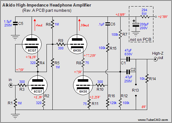 Now on to circuits. The schematic from the last blog showed an Aikido headphone amplifier designed to drive 300-ohm (and higher) headphones. It uses the 6H30 with a high idle current of 30mA and 75-ohm cathode resistors. The trade here is that linearity has been bought at the expense of a higher output impedance. Was it a good trade? Ideally, the Sennheiser HD-650s would prefer both low distortion and low output impedance. But forced to choose, I’ll take low distortion any day. For those who aren’t sure, a simple experiment can be preformed: tack solder one end of a cathode resistor bypass capacitor (1 kµF to 4.7kµF, 10V) across each cathode resistor; hard solder the other end to the resistor. Now listen and measure; then unsolder the tacked soldered end of each capacitor; listen and measure; then re-solder; listen and measure; repeat as needed. Yes, the electrolytic does add its own nasty sonic signature, nonetheless, the test would be revealing.
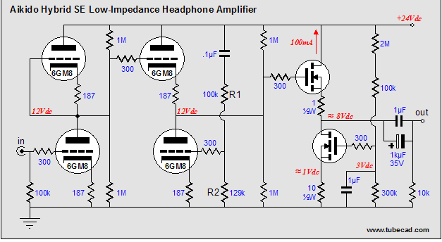
Aikido hybrid headphone amplifiers 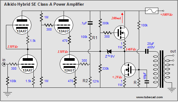 The output from the MOSFET would then either capacitor couple or transformer couple to the loudspeakers. Well, such a circuit could be modified to drive headphones without having to resort to an output transformer. 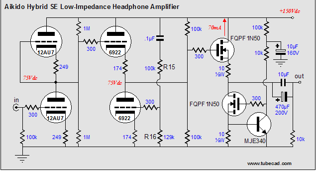 In the above circuit, a relatively low-wattage (and cheap) MOSFET is driven by the Aikido front end. The only liability here is the wasted heat due to the heavy single-ended idle current. sadly, only a few volts of output is needed, but at a relatively high current. the workaround might be to use the low-voltage king, the 6GM8, and a 24-volt power supply for both audio B+ and heater power supply voltage. 
(Yes, batteries could be used, but not car batteries. A car battery is designed to start a car, nothing more, as the alernator will take over supplying the voltage once the car is running. Marine batteries, on the other hand, are desinged to start boat engines and to power the boarts electronics when the engine is turned off. In other words, marine batteries are designed so that they can provide many hours of slow discharge, while car batteries are designed to provide huge spurts of current. Marine batteries cost more than car batteries and they are worth it.)
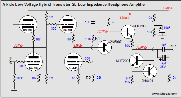
Now, 100mA of idle current is against only 24 volts (2 x 2.4W), not 70mA against 150 volts (2 x 10.5W). Much less heat and a much lower wattage MOSFET can be used. Why is low-wattage a disable feature? Low capacitance. High-wattage MOSFETs bring a huge input capacitance overhead, something which the 2mA of idle current from the 6GM8 is not up to task. Remember, it take current to charge and discharge capacitance quickly. So which MOSFET should be used in this circuit? My first stab was the 2N6660, which I have played with in the past and which I liked, because of its linearity. However, the current price for this little MOSFET is over $25. Ouch! If you know of a cheaper replacement, let me know. 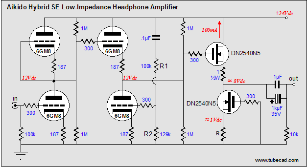 Above, we see a depletion-mode MOSFET being used. This MOSFET can conduct a good deal of current with its gate negative to its source, much like a tube. The DN2540N5 draws an IDSS current of at least 150mA and comes in a TO-220 package, with a 15W dissipation limit. The source resistor R will have to be hand selected (something between 3.3 to 6.8 ohms will probably accomplish the 100mA idle current). Therefore, are we done with this circuit idea? No. in fact, I know many will use some 125W power MOSFET, as they are so cheap and readily available. For these reckless types, the following circuit will work better, as the PNP transistor will be better able to drive the high input capacitance and it will better ceter the output voltage near the 12-volt center mark, while the NPN transistor at the bottom of the circuit automatically sets the idle current through both MOSFETs. 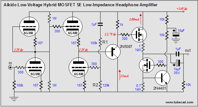 Now, some do not like the MOSFET sound, actually preferring the sound of transistors. For them the following circuit should bring a smile to their ears. The MJE200 is a great little transistor.
Next time
//JRB
|
|


| www.tubecad.com Copyright © 1999-2006 GlassWare All Rights Reserved |