| John Broskie's Guide to Tube Circuit Analysis & Design |
27 June 2006 DACs & Tubes
Digital-to-analog converters (DACs) and vacuum tubes: it’s odd that I haven’t covered this topic before. This topic is so big that several blog entries will be needed no doubt. When I mentioned that I was going to cover this topic, I was asked, "What’s a DAC?" My answer tickled me so much that we will take a small detour on the way to DACs and tubes. 
Today, we are all dualists, happily splitting existence into two parts; holding the view that the world consists of (or is only explicable as) two opposing entities. For example, mind vs. matter, soul vs. body, freedom vs. determinism, subjective vs. objective, yin vs. yang, good vs. evil, the faithful vs. infidels, blue vs. red states, or some other pair of different and irreducible principles. So ingrained is the dualist view that few are conscious of holding it, just as fish are not conscious of the ocean. Don't believe me, just ask around. Although few will admit to being a dualist, most will tell you that they believe in a divided universe, that the laws of physics do not apply to the mind or soul, for example. (Here’s an interesting example, even those who believe that Pentiums can and do think and, and yes, that they are just as capable of consciousness as any of us—strong artificial intelligence proponents, in other words—even these extreme materialists believe in a software-hardware dualism.) The big problem all types of dualism faces is that if there are two primary, fundamentally opposed entities, like spirit and flesh, how do they interact? How does a mass-less entity like your soul push around a mass-filled entity like your body? Well, a few hundred years ago, an answer was offered by the French philosopher/scientist/mathematician, René Descartes. 
As the father of modern philosophy, science and mathematics, and a certain semifinalist in the contest of the greatest minds that ever lived, Descartes was no simpleton. (If you think otherwise, Isaac Newton, for one, would vociferously argue the contrary. Most certainly, Newton could not have been Newton without Descartes broad shoulders to stand on. Moreover, we can add Einstein to this list. In fact, many see Einstein as having applied Cartesian corrections to Newtonian physics.) While Descartes did not invent dualism—Zoroaster or Plato probably should get the credit—he did buttress and promote it more successfully than just about anyone before or since (with a knowing nod to Kant). 
Well, was he right? Well, are there mental states independent of matter? Is there physical material independent of thought? Perhaps the better questions is, "Who knows?" One interesting finding is that when radioactively-tagged LSD is administered to a subject, most of the LSD is found traveling to the liver, an organ not much celebrated in higher conscious circles. The little LSD, and I do mean little, that finds its way into the brain most of this fraction lodges itself in the pineal gland. Interesting. 
What does this have to do with DACs and tubes? If you listen to music through an iPod or a computer’s sound card or CD or DVD player or records that were mastered from digital recorders, then you live with a sharp dualism: sound reproduction based on digital and analog principles. The digital world is filled with zeros and ones; the analog world, with linear electronics and woofers and tweeters. These two worlds have almost nothing in common, yet we do listen to MP3 files and CDs. The DAC is like Descartes’ pineal gland, in that it mediates between digital and analog. However, unlike the pineal gland, it cannot act as a go-between in both directions, as it only translates jerky zeros and ones into flowing and ebbing analog signal. An analog-to-digital (ADC) converter renders sinewaves into digital data, data that could reside on magnetic tape or optical disks or even in a printed book. 
In other words, the DAC is critical. Should it neglect or mangle the music encrypted in those ones and zeros, no amount of single-plate 2A3s or beeswax-filled coupling capacitors and hand-carved horns and $3,000 power cords is going to restore the missing music. Therefore, using the best DAC you can afford is money well spent. Fortunately, even the best DACs are not all that expensive; compared to $3,000 power cords, they are downright cheap; for example the highly esteemed AD1955 costs less than $8 each; the WM8740, less than $6. No mater which DAC you chose, be sure to read carefully the data sheet for clues and tips on how to get the most from the device. For example, the PCM63 contains a 2mA constant-current source to load its current output. This CCS can be disconnected from the output and replaced by another CCS of our own design or maybe left out altogether, as the 2mA offset current might be supplied by our tube-based I-to-V converter stage. Two types of DACs 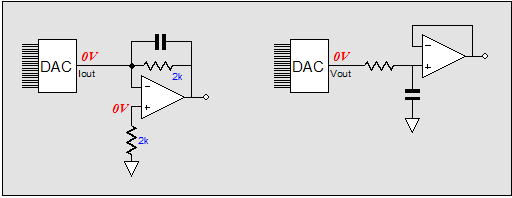
By the way, Wolfson created a very clever voltage-output DAC in the WM8740. Below is a quote from EDN:
Clever, very clever. Did you spot the neologism (hmmm...is it a "new word" or just plain "not a word"?): “nonidealities.” Since “ideality” can mean existing as an idea, not a reality, does a “nonideality” exists as a reality, not an idea? Or does it just mean icky stuff? Multi-bit & delta sigma Which is better, voltage-output or current-output? (Those who expect to me to write “Better for what?” will not be disappointed.) Better for what? Better sounding? Better to hook up to vacuum tube circuitry? In theory, I would have to declare the current-output DACs as the optimal sonic choices, as they would hold one fewer solid-state circuit, the current-to-voltage converter, as I have never seen a DIP DAC with tube sockets imbedded on top. On the other hand, if we focus on practical reality, then the voltage-output DAC is a much better choice for tube-based output circuits. Why? Because tubes are relatively high-impedance devices and current-output DACs, like inductors, prefer low impedances, whereas voltage-output DACs, like capacitors, prefer high-impedances. For example, it would be a breeze to wind a low-pass inductor for a 0.1-ohm woofer, but painful to do the same for a 1Meg woofer; just as it would be cheap to buy a high-pass capacitor for a 1Meg tweeter, but hugely expensive to do the same for a 0.1-ohm tweeter. Do the math. In addition, current-output DACs put out a varying current that must be converted in voltage, if a triode’s grid is going to receive the DAC’s output signal. Although all the DAC data sheets advise against it, many tube practitioners (I among them) have loaded the DAC’s current output with a resistor to perform the current-to-voltage conversion. Usually, the I-V resistor is small in value, say 100 ohms, but note how far from zero ohms we have traveled. See PCM63 I/V resistor value tests to read more on I-V resistor values and their effect on the DAC's output. (I did my own tests with the TDA1541 and PCM63 DACs and I-V resistor values. I found that 60 ohms sounded better than 100 ohms and my guess is that 10 ohms would sound better still.) The DAC’s 1 to 2mA output current against 100 ohms equals 0.1 to 0.2V of output, which isn’t too small, but it is 20dB to 14dB lower than 1V of input signal. Against 10 ohms, only 0.01V would develop, which would be 40dB lower. 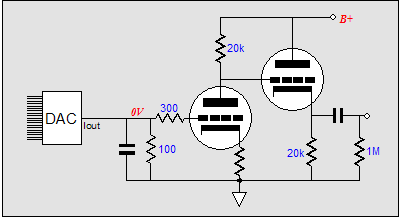
The other workaround is to use a step-up transformer to couple the DAC’s output to a higher impedance load, but this seldom works as well as we would hope, as 1mA of output current is so small; 10-50mA would be much more useful. Furthermore, wide-bandwidth, low-noise, well-shielded small-signal transformers are both rare and expensive. Still, there is a lot to be said for breaking the ground connections; and the low-pass high-frequency attenuation that the transformer provides can only help. 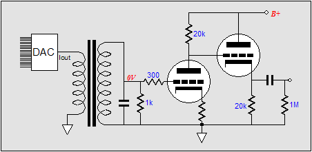
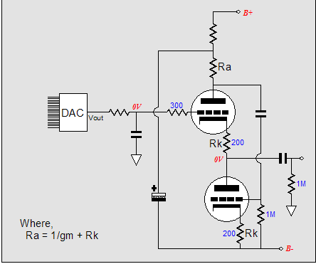
Furthermore, many current-output DACs were designed with the strict expectation of a near-zero input impedance from the I-V converter stage. Unfortunately, such a low input impedance is all but impossible with common vacuum tubes like the 12AX7 or 6DJ8, unless you include many tubes and much feedback. (The DAC’s output contains a good bit of high-frequency energy, which is bad news for most feedback amplifiers, so high feedback ratios and multi-stage amplifiers are to be avoided.) In contrast, a 12AX7 would be quite happy to accept a 1-volt input signal from a voltage-output DAC. (One volt of signal is about 200 times greater than the output of a moving magnet phono cartridge, which a 12AX7 has no little problem amplifying.) In fact, we now run into a new problem: too much gain. Some voltage-output DACs put out over 2V of peak output, which against the 12AX7’s gain of 50 or more, provides far too much gain, as most power amplifiers require only 1V to be driven to full output. Some have used step-down transformers or voltage dividers to reduce the DAC’s voltage output to levels better suited for the tube amplifier. So, the current-output DACs provide too little gain (when working into a I-V converter resistor) and the voltage-output DACs provide too much gain. Or do they? Why does the tube output stage have to provide any gain, if the voltage-output DAC’s output is 2V? The quick answers are that cathode followers are evil and that some high-frequency filtering must be implemented on the output signal. Well, I buy the second argument. However, if an intelligently-designed cathode follower is used, there is no reason why the sound must suffer. Below is a simple and good sounding cathode follower (the seemingly redundant cathode resistor is critical in buffering the cathode from excessive capacitance and for linearizing the triode's transfer curve, at the cost of a slightly higher output impedance). 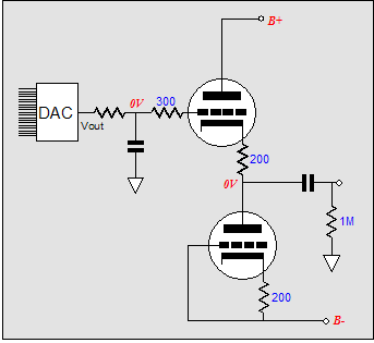 This simple cathode follower shown above is single-ended in operation and posseses a very good PSRR figure, as long as both negative and positive power supply rails share the same noise signature, equal in amplitude but opposite in phase. The White cathode follower below is a push-pull circuit that also exhibits a low noise output and an output impedance half that of the simple cathode follower; it can also put out twice the current swing. The simple RC high-frequency filter at each input is there to shunt away the high-frequency nastiness. A more complex circuit could be used, but I would recommend using a passive filter, maybe even an LC filter. Why? The higher the frequency, the less effective an active filter becomes. (Conversely, the lower the frequency, the better suited the active filter becomes.)
If the following stage holds its own input coupling capacitor, then both cathode-follower circuits can be direct-coupled at the output.
Now for something really important
I think that I will wait for an ivory version that sells for $2,500 instead. Remember, the first rule of high-end audio: its only as good as it costs.
Next time //JRB |
 Aikido PCBs for as little as $24 WHAT IS AN AIKIDO AMPLIFIER?
The Aikido tube topology, created by John Broskie, delivers the sonic goods. Since the Aikido circuit came out in the Tube CAD Journal, people have been building it and marveling at its sound. A prediction: just as the 1980s were the cascode decade and the 1990s, the SRPP decade, this decade will be known as the Aikido decade. Why? This amplifier circuit offers voltage gain, low distortion, low output impedance, and a high PSRR figure—all without a global feedback loop. Better than SRPP Flexible Always Biases Up Correctly Functions Flawlessly No Popping Sounds at Startup, Less Distortion A Sound that’s Hard to Improve Upon AIKIDO AMPLIFIER PCB What makes them superior? First of all, they look fabulous and feel solid in the hand: extra thick (inserting and pulling tubes from their sockets won’t bend or break this board), double-sided, with 2oz copper traces, clean silkscreen and solder mask. (The board holds two sets of differently spaced solder pads for each resistor, so that radial and axial resistors can be easily used. Each capacitor finds several solder pads, so wildly differing sized coupling capacitors can neatly be placed on the board.) Each board holds two Aikido linestage amplifiers; so, one board for stereo unbalanced or one board for one channel of balanced amplification. The boards hold two coupling capacitors, each finding its own 1M resistor to ground. The idea here is that you can select (via a rotary switch) between C1 or C2 or both capacitors in parallel. Why? One coupling capacitor can be Teflon and the other oil, or polypropylene or wax and paper…. As they used to sing in a candy bar commercial: “Sometimes you feel like a nut; sometimes you don't.” each type of capacitor has its virtues and failings. So, use one type of coupling capacitors for old Frank Sinatra recordings and the other for string quartets. Or the same flavor capacitor can fill both spots: one capacitor would set a low-frequency cutoff of 80Hz for background or late night listening; the other capacitor, 5Hz for full range listening. Or if you have found the perfect type of coupling capacitor, the two capacitors could be hardwired together on the PCB, one acting as a bypass capacitor for the other. The board assumes that a DC 12V power supply will be used for the heaters, so that 6.3V heater tubes (like the 6SL7 and 6SN7) or 12.6V tubes (like the 12SL7 or 12SN7) can be used, for example on an octal board. Both types can be used exclusively, or simultaneously; for example 12SX7 for the input tube and a 6BX7 for the output tube. (A 6V heater power supply can be used, as long as all the tubes used have 6.3V heaters; and an AC heater power supply can be used, if the heater shunting capacitors are left off the board.) The boards are four inches by ten inches, with eight mounting holes. Boards are made in the USA and come with instructions that include schematic and recommended part values. A real E-mail from a new Aikido PCB owner:
Visit our Yahoo Store for more details: | |||


| www.tubecad.com Copyright © 1999-2006 GlassWare All Rights Reserved |