| John Broskie's Guide to Tube Circuit Analysis & Design |
01 July 2006
I had planned to dive into the subject of balanced output DACs, but a reader sent me a troubling e-mail. He asked why I keep recommending using the Aikido amplifier as the front end of an SE power amplifier, when the Aikido holds such a high output impedance. What!!!!! I asked what made him think the output impedance was high, and just how low an impedance he thought was needed to drive a 300B's grid. His answer was that he had read on a popular DIY website that the Aikido’s output must be high, as its output connects to the bottom triode’s plate. His second answer was that the output should be less than 10k, which was the value that he liked best for the grid-stopper resistor for the 300B. Like brush fires in the hot Californian hills, Net-spread misinformation is hard to put out, so let’s set the record straight (if only for a month or two). The Aikido enjoys a low output impedance, not a high one. For example, a 6DJ8/6922-based Aikido line amplifier can easily offer a low 300-ohm output impedance. After all, as the Aikido’s output stage is a modified cathode follower, we should not be surprised. Thus, the output impedance is roughly equal to 1/gm + Rk. For example, the inverse of a 10mA/V transconductance equals 100 ohms plus a 200-ohm cathode resistor add up to an output impedance of 300 ohms. I don’t know about you, but 300 ohms is a low output impedance compared to a comparable grounded-cathode or SRPP amplifier. And it is 1/33 the 10k limit the reader specified. Actually the bottom triode’s rp helps lower the output even further, so a closer approximation would be (The other Aikido Web-spread myth that I hear is that the Aikido is a modified SRPP circuit. It is not. The “PP” in “SRPP” stands for “Push-Pull,” not “Pleasing as Punch” nor “Perfectly Pure.” Nothing in the Aikido circuit pushes and pulls at the same time; it is a pure single-ended topology from input to output. Both of these mistaken takes on the Aikido circuit are due to oversimplifications of topology. In other words, just because the output connects to a plate does not force a high output impedance on a circuit—ever hear of an anode/plate follower? Just because one triode stands atop another does not define an SRPP topology—ever hear of a cascode amplifier or White cathode follower.) Aikido cathode follower 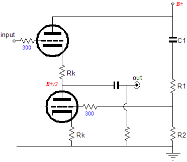
Aikido Cathode Follower The Aikido cathode follower gain and distortion are slightly lower than the simple cathode follower's and its output impedance is slightly higher. However, its PSRR is substantially better. Considering that the simple cathode follower already affords a good PSRR figure, a lower figure still is exceptionally amazing news. How good? In theory, infinitely better; in reality, maybe 1/mu better.
Noise! 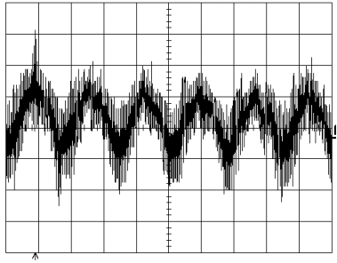
I hear this complaint quite often and my answer is always the same: "So you like hearing power supply noise?" The usual reply is a sheepish, “Well, no.” An analogy that might prove useful is to imagine we all work at a bottled juice-flavored drink company. Some are obsessed with the purity of the fruit extract. “Where else is the flavor going to come from?” they argue. Others stress the importance of the food coloring used to tint the drink. “Who wants to buy an ugly-toned drink?” they ask. Which leaves me fighting hard for the for the best extract and the cleanest bottles and purest water. Why? How else are we going to taste the flavor or see the tint? Or, would a gourmet meal really taste better on a dirty dish with a filthy fork? The modern classical composer, John Cage, might have been right when he said,
Nonetheless, we should endeavor, as a stellar PSRR allows more music to be heard. Besides, good low-noise performance is one of the few desired attributes where solid-state can make a strong competitor. By pulling this ace from the solid-state player sleeve, we stand a much better chance of winning the whole pot. A better question is: Why do so many resent my insisting on adding low-noise to usual design goal of low distortion? Of course, my sins don't stop with noise. It just irks them when I stress not only power-supply noise, but grounding practice, and clipping behavior, and worst-case fault conditions, and…. Noise just stands out, as so few ever concern themselves with it. The answer, I believe, is that for many tube-circuit designers—and many solid-state designers—only one design goal can be considered at a time and that goal is usually low distortion or maximum power output or wide bandwidth. Like a juggler who can only toss and catch one ball, these designers create circuits that address only one key variable and ignore the rest. And ignoring noise is easy, as the B+ voltage is assumed to be clean to start with, so why not focus on just distortion or on low output impedance, they reason. To be frank, there is something almost admirable in the usual single-issue circuit designer’s determined tunnel vision; for them there is only one overriding design goal and nothing else much matters, like the law-loving lawmaker who might argue that since criminals disobey the law, we need a new law requiring criminals to obey the law; thereafter, there will be no crime. Or economics professors that believe that a 100% tax rate will ensure the highest tax revenue. (How long would you work for nothing? How long would the IRS agents work for nothing might be the better question.) 
The single-attribute mentality is too many times true of loudspeaker design: often a successful loudspeaker will only prove excellent in only one key area, such as high-frequency extension, or low-frequency extension, or purity of midrange, or none of the aforesaid virtues but providing only excellent imaging, or only high efficiency. Suppose someone devised a multidimensional score card for these designs featuring the categories of bass, mids, highs, imaging, and dynamics. One design might merit 4, 10, 3, 5, and 4. Another loudspeakers might achieve a score of 3, 5, 10, 7, and 4—and it it too would sell well, as there are those who value good highs above all else. But a loudspeakers that scored 8, 8, 8, 8, and 8 may not sell well at all, even though its complete score total would be higher than the other two loudspeakers, as it would fail to capture the attention of the unidimensional buying public. The Aikido amplifier achieves four goals: low distortion, low noise, low output impedance, and no feedback loop. (And, yes, in that order.) Any of the first three goals can be individually increased, but only at the cost of the others. Thus, the Aikido amplifier should not be viewed as being just a low-noise circuit, but rather a low-distortion, low-noise, low-output impedance, and feedback-free circuit.
Back to the Aikido cathode follower 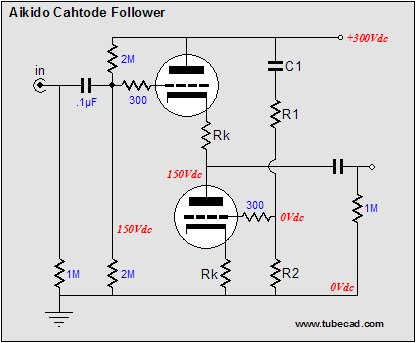
Imagine that the output coupling capacitor is infinitely large in value and that the load impedance is zero ohms and that the input is grounded. Any signal (power-supply noise) on the top triode’s plate will impose a current conduction variation in the top triode equal to Inoise = Vnoise / (rp + [mu + 1]Rk]. The bottom triode must match this current variation to null the noise at the follower’s output. Since, in a triode (by definition), a grid is mu times more effective than the plate in controlling current conduction, the bottom triode’s grid must see the power supply noise dived by the mu of the triodes used. For example, a 6AS7 (with a mu of 2) will need to see half of the power supply noise at its grid; a 12AX7 (with a mu of 100), 1/100th of the power supply noise at its grid. Therefore, the voltage divider resistors must mimic this ratio: and thus, R1 = (mu + 1)R2. For example, with a 6AS7 (with a mu of 2), R1 would equal R2; with a 12AX7 (with a mu of 100), R1 equals 99 x R2. Capacitor, C1, needs to big enough in value to ensure enough low-frequency bandwidth to prevent excessive phase shifts at 50 or 60Hz. Thus, C1 ≥ 159155/(R1 + R2)/20, where the answer is in µF. Could the Aikido cathode follower be used with a bipolar power supply? Actually, as long as the negative and positive rail share a perfectly related noise, equal in amplitude, but opposite in phase, then the following circuit works beautifully: 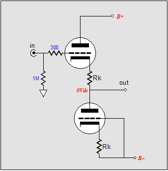 Conclusion
Next time 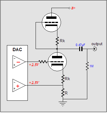 //JRB |
Only $12.95
Download or CD ROM www.glass-ware.com
|
|||


| www.tubecad.com Copyright © 1999-2006 GlassWare All Rights Reserved |