| John Broskie's Guide to Tube Circuit Analysis & Design |
07 July 2006
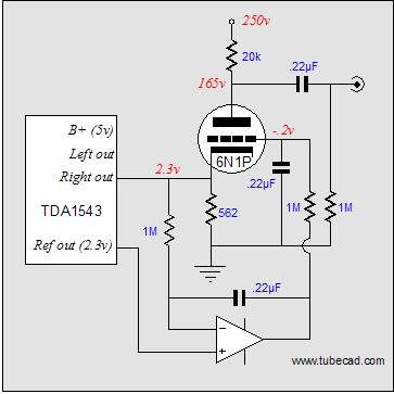
NOS How do tubes fit in this picture? Easy, the tube catches either the current or voltage output of the DAC and amplifies the signal and then it drives the passive low-pass filter. As you can imagine there are many possible schematics for such a job. Below is just one possibility. The TDA1543 expects to see a fixed DC voltage at its current output (usually 2.3V) and it provides a voltage reference output, so that an OpAmp can use this voltage as its effective “ground” voltage. We can also use the reference voltage with a DC servo loop that keeps a triode’s cathode locked at 2.3Vdc. 
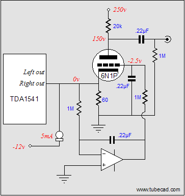
The TDA1545 uses a slightly more complex voltage reference, but the same technique can also be used with this DAC. Ideally, TDA1541 (double crowns) should be used, as this is one of the finest DACs ever made. However, its current output expects to single ended 0V at its output. Thus, the above circuit needs some adjusting:
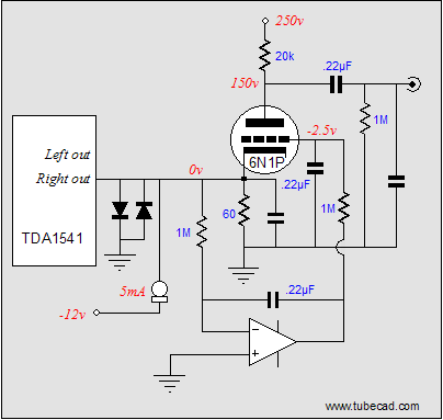
The cathode is loaded by both the 60-ohm resistor and the constant-current source. The DC servo loop adjusts the grid to achieve zero volts at the cathode. The only thing that scares me is what may happen at startup, when the tube is cold and not conducting. Will the extremely expensive DAc be damaged? A workaround would be to protect the DAC’s output by placing several diodes wired back to back, so that the output can never see a voltage greater than +/-0.7V.
Next time
//JRB
|
|
| www.tubecad.com Copyright © 1999-2006 GlassWare All Rights Reserved |


