| John Broskie's Guide to Tube Circuit Analysis & Design |
21 August 2006 Death, Taxes, and Spam
Of course, it might not have been organized criminals in Russia who performed the good deed, but I like to hope for the best. And, of course, this type of vigilante justice can easily get out of hand. First it’s just king spammers, then it’s Madonna…then it’s global-warming-inducing audiophiles, who would rather enjoy their music via hot vacuum tubes and the world be damned with soft ice cream and Al Gore movies, rather than accepting earth-friendly class-B and class-D solid-state amplifiers. Still, the old utilitarian felicity calculus cannot easily be dismissed. When I punched the numbers in my Bentham's Hedonic hand calculator, I confirmed that one spammer's untimely demise < the public's hassle of dealing with 35,000,000 spam e-mails a day.
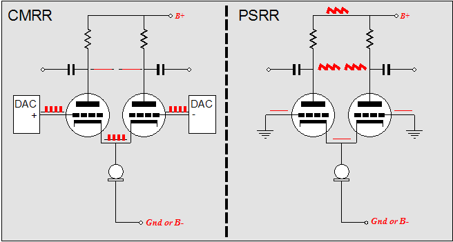
Balanced-Ouput DACs & Differential Amplifiers When presented with a balanced input signal source, most tube fanciers’ first response is to turn to the classic long-tailed differential amplifier. The reason is not hard to find. The differential amplifier accepts a balanced input signal and delivers a balanced output signal. In addition, it offers an excellent CMRR figure, which means that common-mode noise will be dropped from its output. 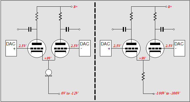
True enough. Certainly a differential amplifier—when the common cathode resistor’s value is large or when a constant-current source attaches to the common cathodes—can readily reject a signal common to both of its inputs.
Yet, this marvelous feature may not be enough to ensure a low-noise design. Why? The differential amplifier suffers from a horrible PSRR figure. How so? The hand that gave also took. The large-valued common cathode resistor (or that which is both more likely and better, an active constant-current source) that made the great CMRR possible also reduces the PSRR to nearly zero. Think about it. If the constant-current source results in a constant current flow through each plate resistor, then—in the absence of any input signal—a constant voltage must exist across each plate resistor. (One means to understanding is to imagine that the plate resistors were replaced by high-voltage batteries or zener diodes; remember, a constant voltage, because of constant current.) This means that the noise at the B+ reflects—in its entirety—to the amplifier’s outputs. Another way of looking at it is that the higher the resistance into which the common cathodes terminate, the higher the plate impedance at each output. The impedance at each plate is equal to 2(mu + 1)Rk +rp. Thus if resistance Rk equals 0, the output impedance is simply rp; if resistance Rk equals infinity, the output impedance is equal to infinity. Now a two-resistance voltage divider that holds a bottom resistance equal to infinity does not attenuate much at all. By the way, if a small valued common-cathode resistor is used, then the CMRR falls apart and the PSRR improves. In other words, forgoing a constant-current source or a large valued common-cathode resistor allows common-mode signals to be amplified almost as much as balanced signals. In addition, effective plate impedance drops to 2(mu + 1)Rk +rp. 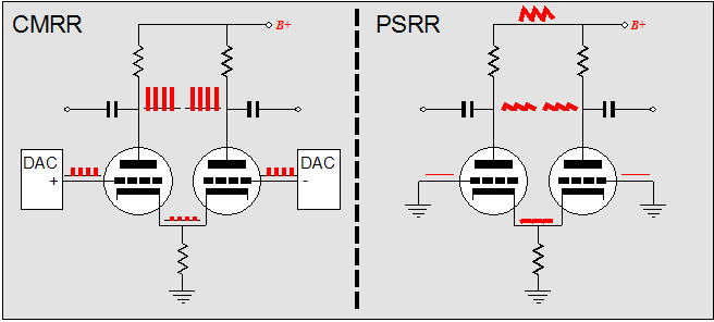
There is a workaround, which greatly improves the differential amplifier’s PSRR figure. It has been covered before in this journal, so I’ll only give a brief outline. If an anti-phase noise signal is introduced at the common cathode connection, then the two triodes’ conduction will vary in anti-phase with the noise, causing the power supply noise to be cancelled at the plates. This inverted power supply noise signal can be sampled from the B+ rail or derived from a negative power supply rail that holds an equal, but out-of-phase, noise signal. 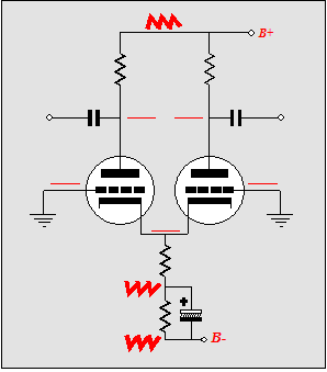
Another approach is to use the last half of the Aikido amplifier, with a slight modification. In the Aikido amplifier, the input stage’s output holds 50% of the B+ noise, which the modified cathode follower output stage nulls from its output. On the other hand, the differential amplifier will present close to 100% of the B+ noise, so the ratio of inject noise must also equal 100%, which is easily accomplished by not using the two-resistor voltage divider in the Aikido output stage. 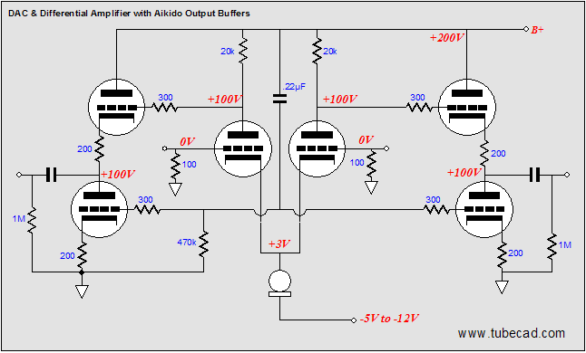
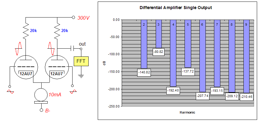
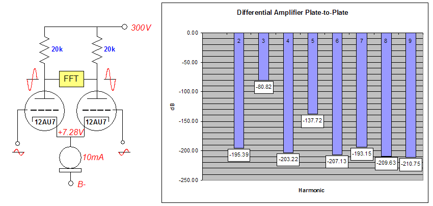
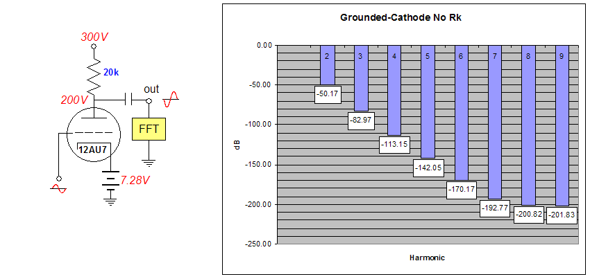
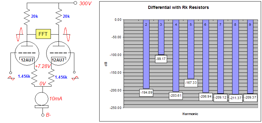
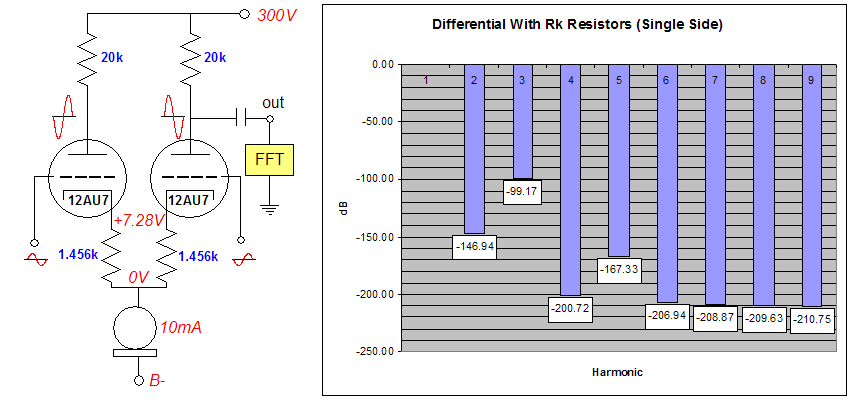
(Actually, a bit more than 100% of the power supply noise needs to be injected, but then a bit less than 100% will be presented from the differential amplifier’s outputs; a wash, in other words.) So have we arrived at audio bliss? It depends. There is an additional problem: the differential amplifier produces a fairly mediocre distortion figure. Yes, it may hold a constant-current source; but the current source attaches at the cathode, not the plates. Moreover, it only offers 100% negative degeneration to common-mode input signals. Non-common-mode signals see a transfer function a little worse and a good bit better than the tube would deliver in a comparable grounded-cathode amplifier, with no cathode resistor (or with a heavily bypassed cathode resistor). So although we have eliminated much of the DAC’s noise and the power supply noise from the output, we still have a so-so distortion figure. Actually, the situation is bit more complex. In terms of even-order harmonics, the distortion on each individual output is greater than the differential sum from both outputs; in terms of odd-order harmonics, the distortion on each individual output matches that of the differential sum. The following graphs are the result of running four simulations in SPICE. (Half of the readers say to themselves, “Excellent, finally some hard reality; nothing like the expert confirmation that SPICE provides.” and the other half say, “Oh no, it’s Alice-in-Wonderland time; I have never held or heard a virtual tube.” Who is right? Neither, really, as the truth lies somewhere in between these two extremes. Yes, the SPICE model is far too optimistic in terms of linearity [it assumes an unvarying mu; reality disapoits, with a mu that decreases with plate voltage and decreasing current], so a real test with real tubes would show higher distortion. Nevertheless, the performances relative to each topology remain the same. So, if we ignore the specific readings and only observe the trends, the results are quite useable.)
Note that both graphs show the same odd-order distortion and that the plate-to-plate results show the typical push-pull notching of even-order harmonics.
The battery was used instead of a cathode resistor with a large-valued bypass capacitor, as SPICE works better with less parts in a circuit. Alternatevely, the cathode could have connected directly to ground and the B+ voltage reduced by 7.28 volts. In the above graph, we see a bit less odd-order harmonics and quite a bit more even-order harmonics. Now let's see what a little cathode degeneration does for us. 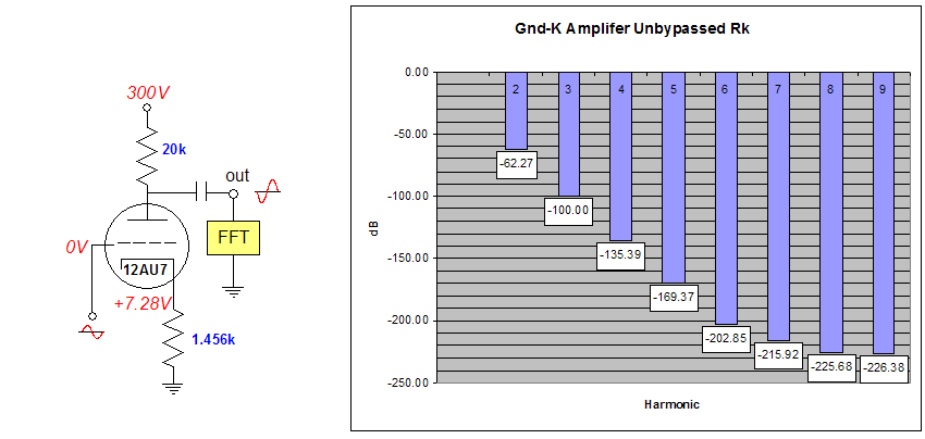 A bit of 2nd harmonic and then really nothing that counts that much, as anything below -100dB is pretty much off the ear's radar screen. Indeed, this is what the ear likes to see. Or should I say, "This is what the eyes likes to hear"? As Tom Waits would put it: "The vacuum tubes have been drinking, not me." Actually, as befits someone so interested in electronic topology (particularly in elucidating the underlying structures of things), I delight in rhetorical figures, such as zeugma, enallage, tmesis*. (The last sentence is a trivial example of asyndeton, the omission of an expected conjunction.) “This is what the ear likes to see,” is an example of catachresis, Ancient Greek for “misapplication,” (a subset of metonymy) where an apt word substitution is made that jars our sensibilities. For example, in King Lear,
Or when E. E. Cummings wrote,
Okay, back to tubes. Some will cry foul at seeing the last schematic and graph. They will argue that the grounded-cathode amplifier with an unbypassed cathode resistor will develop much less gain than all the previous circuits, so it should be expected to have much lower distortion. I don’t entirely disagree. In some absolute sense, there is a little bit of substituting oranges for apples; but in a practical sense, nothing unfair is perpetrated. Yes, this circuit will yield less gain, but then less gain is what we need (in fact, it produces about half the gain, which is still too high, 6.5 vs 13.1 from the other topoologies). As the DAC’s internal I-to-V stage provides enough signal amplitude to drive most amplifiers to full output, any more gain can be a nuisance. Additionally, this comparison is fair in that the same input signal is shared by all the circuits; it is what we would get, if we built each circuit. None of this is a big secret. In fact, the differential amplifier is often modified by the addition of two resistors either at the tubes' cathodes, at the transistors' emitters or at the FET's sources. These resistors serve to linearize the differentially opposed devices. Unfortunately, this practice only became popular under a solid-state sensibility, so the effective solid-state practice of adding two 100-ohm resistors is too often applied to tube differential amplifiers, with little effect. Transistors have screamingly high transconductance compared to a 12AX7 or, even, a 6DJ8. For a 12AU7, 100 ohms is next to nothing. If we want real benefits using tubes, we need to substitute 1k to 2k resistors. Below, we see the effects of using 1,456-ohm resistors.
The downside of adding these extra resistors lies in the extra voltage that they will displace, as the option of forgoing a negative power supply rail disappears with the resistor-displaced cathode voltage. Of course, if the builder intends to generate a high-voltage negative power supply rail and large-valued common-cathode resistor, this will not be an issue.
Next time //JRB
* Zeugma is the dropping of a verb in parallel clauses; for example, "But passion lends them power, time means, to meet." Enallage is a purposely made grammatical mistake in order to achieve emphasis; for example, "We was robbed." Tmesis is the breaking of a word in two; for example, "In two words, im possible." Or the ever-popular, "unbe—f*cking—lievable." |
|


| www.tubecad.com Copyright © 1999-2006 GlassWare All Rights Reserved |