| John Broskie's Guide to Tube Circuit Analysis & Design |
28 August 2006 Mystery Solved The mystery is solved. This whodunit involved many hits, mobsters, missing links, and much head scratching on my part. You see, every week I get an ISP generated tabulation of this website’s popularity in the form of total hits (190,870), number of unique URLs (4,357), total kilobytes transferred (3,024,460), and a long list of the most commonly accessed URLs and each URL’s number of hits. As would be expected, the site’s index page gets the most hits, followed by the most recent blog entry. Then the same popular old articles are always recorded at the top, such as “Cars, Planes, and Circlotron,” “SRPP Deconstructed,” and “Active Crossovers and Filters.” Nothing mysterious so far. But since last year, I have been surprised at the number of hits for the blog entry on Jeb’s Amplifier. Sure the entry was interesting, but so are many other entries that do not garner nearly the same number of hits. My guess was that Jeb or someone else owns a popular tube-based website with a link to that page. So I went hunting, but as far as Google was concerned, no site other than mine linked to that blog entry. Well, what about newsgroups or forums? Nope, nothing. If there are no links to a webpage does it exist?  The answer it seems is yes. I noticed that one image from that blog entry was getting twice the hits that the page itself got. Bingo, mystery solved. When someone types “mobster” into Google’s Image Search, the Mobsters.PNG that I created comes up second, right after the poster for movie with the same name.
More balanced-output DACs and tubes (Although, I have to say that just because the topic is DACs and tubes doesn’t mean that useful tricks and principles cannot be gleaned that would apply to phono preamps, shunt regulators, OTL and headphone amplifiers, and other tube circuits, for example a balance line stage is perfect candidate. Many times, too many times, I have had friends give me a big “Why?” upon seeing me examining a schematic for a tube-based photo-multiplier or sonar circuit. Why, indeed. If you look in the same places repeatedly, it is unlikely that you will find anything new.) .png)
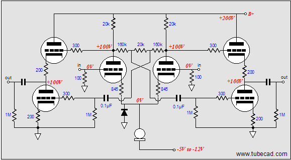
Last time we left off, I was extolling the virtues of un-bypassed cathode resistors in a grounded-cathode (and differential) amplifier for their ability to linearize the output. I should also mention that these resistors have downsides, as they increase the output impedance, reduce the gain realized, and worsen the PSRR. With the cathode tied directly to ground or with a bypassed cathode resistor, Zo = rp || Ra, but the addition of un-bypassed cathode resistance increases the output impedance to Zo = ([mu + 1]Rk + rp) || Ra, where “||” stands for in parallel with, e.g. X || Y = XY/(X +Y). The gain goes from Gain = µRa/(rp + Ra) to Gain = µRa/(rp + Ra [mu +1]Rk). The PSRR (in dBs) goes from 20Log (rp / [Ra + rp]) to 20Log ([rp + (mu + 1)Rk] / [Ra + rp + (mu + 1)Rk]). In a minimalist design, say a lone 12B4-based grounded-cathode amplifier, these disadvantages may well sink a line amplifier’s usefulness. In a more complex circuit, wherein a buffer receives its input signal from the newly linearized differential amplifier, where the differential already-poor PSRR could hardly be made worse, and where extra gain is not needed, these cathode-resistor-induced drawbacks do not exist. (One moral we can take here is that expecting a supremely-simple, single-stage circuit—the Zen amplifier and SRPP might be good examples—to do everything is just expecting too much, as delivering high gain, low output impedance, and a good PSRR is a lot to expect from one active device. With two stages, however, each stage can do only what it does best.) Adding un-bypassed cathode resistors to the differential amplifier is easy, although a negative power supply rail (-5V to -12V) will probably be needed. (The LM334 can work down to 1V, which means that this constant-current source IC could be used with the +2.5V DC offset provided by many DACs. On the other hand, a complex, discrete-part-based constant-current source might require a greater voltage window in which to operate successfully.) And if the DAC’s output is at 0V, then a negative power-supply rail will definitely be needed.
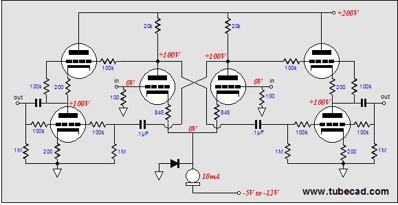
Fixed low-impedance loads and PP outputs This circuit is interesting, as it does so much. First, it exhibits excellent CMRR due to the use of a constant-current source. Second, it achieves an excellent PSRR figure due to the top and bottom output tubes both seeing the same amount of power supply rail noise. Third, it develops equal and anti-phase current swings from the output tubes into the fixed load impedance due to the three-resistor voltage divider that spans the differential amplifier’s plates. (Of course, the actual resistor values will depend on the load and the output stage triodes that are used.) This voltage divider attenuates the drive signal needed for the bottom triodes without attenuating the power supply noise. Fourth, the differential amplifier’s un-bypassed cathode resistor greatly linearizes its transfer function and lowers its gain, which is a desirable goal, as the differential input signal from the DACs provokes a +6dB gain on an already hot signal. The limitation to this circuit is found in its lack of flexibility: a different set of output tubes or a different load impedance means a different voltage division ratio is required. The best workaround is to use a Broskie cathode follower instead. Not only will the Broskie cathode follower work better into an array of load impedances it also offers a more symmetrical output impedance, as both top and bottom triodes work evenly at fighting perturbations at the output.
Aikido and balanced DACs 
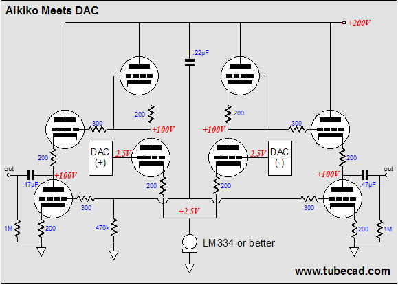
The above schematic shows an Aikido-style differential amplifier and buffer that offers superb performance at the cost of having to use four dual triodes. Not only are un-bypassed cathode resistors used, the differential amplifier is loaded by a symmetrical load. In other words, the differential amplifier’s distortion goes down, because an equally and complementary nonlinear resistance loads its triodes' plates. The output stage holds Aikido cathode followers, which offer low distortion, fairly low output impedance, and great PSRR. Unlike the unbalanced Aikido line stage, which is fairly foolproof, this circuit requires a bit of tweaking, as the constant-current source must be adjusted so that its connection to the cathode resistors is at 0V. In other words, when those cathode resistors are grounded, the top and bottom triodes split the b+ voltage nicely; however, when they connect to spongy constant-current source, the voltage at this connection will depend on the idle current set by the constant-current source. Too much current and the constant-current source will find itself pinched of voltage. In other words, a negative power supply rail is a good idea, in spite of the increased complexity, as at least this way the constant-current source can never be voltage starved. .png)
I know that many are feeling a bit anxious—if not downright panicky—right now, as two schematics have been displayed without specifying the tubes used. What good is a schematic without every part labeled? Except for illustrating topology—the study of the properties of the arrangement of electronic parts that is independent of changes in value or brand—it is of little value. So what is the danger of specifying a part type and value for every part in a schematic? Useful as the schematic might be for the slavish building of the circuit, it obscures intrinsic relationships between parts, which in their totality define an understanding of the topology, the logos, the principle of a circuit. For example, an Aikido line amplifier can be made out of two 211s and two 845s; such an line amplifier might require a 1,200V power supply and four floating high-current heater power supplies, nonetheless the circuit would function the same as a 6GM8-based line amplifier that worked off a single 24V wallwart power supply.
Next time //JRB
|
Only $12.95 Download or CD ROM www.glass-ware.com
|
|||
| www.tubecad.com Copyright © 1999-2006 GlassWare All Rights Reserved |


