| John Broskie's Guide to Tube Circuit Analysis & Design |
15 November 2006 A New High-Voltage Regulator
Ah, the thorny topic of high-voltage regulation. There are so many options: all-tube, all solid-state, some hybrid of the two technologies, series, shunt, DC regulation, AC regulation, linear, switching… Then there is the danger: a mis-wired high-voltage regulator often smokes, if not catches on fire, or—failing such a dramatic exit--when poorly laid out, oscillates wildly. So where does one begin? Or should one begin? Voltage regulators are high-gain, unity-gain amplifiers, which means that they are also high-feedback amplifiers. (If a regulator is an amplifier, what is its input signal? That’s easy: ground.) With all-tube voltage regulators, at least the gain is limited to seldom more than 100, or 300 at the most; with solid-state voltage regulators, the DC open-loop gain can easily be 200,000, as that is the lowly LM741’s open-loop gain. With such a high open-loop gain, layout and wiring practice become critical. A high-voltage regulator just wont tollerate the sloppy point-to-point wiring that goes happily into a feedback-free, single-ended power amplifier. In other words, if I were smarter or wiser, I would stop right here, but then if I were smarter or wiser, I wouldn’t have created GlassWare or the Tube CAD Journal. (About 15 years ago, a friend of mine was in charge of 25 million dollars in venture capital. He told me that he was eager to divert several hundred thousand my way, as long as I promised that my high-tech endeavor would not be in any way audio related and, particularly, not tube-related! If I had been smarter or wiser, I would not have declined the strings-attached, start-up capital. Then back in 1999, when I started the Tube CAD Journal, an acquaintance who ran a soft-porn website told me I was crazy for not following his lead. He worked only a few days a month, but made between $9,000 to $11,000 a month with his website. He proudly explained that he could make more, but that he insisted on splitting the profits with the four naked UC Santa Cruz female students who adorned his website. His definition of "splitting" was interesting: he got half and the four girls got one eighth each. Considering that they did less work than he did—they were photographed one day a month—his arrangement doesn’t seem that egregious. I remember him saying to me, “I am not smart enough to do what you are doing with your software and your website, but I am sure that I am making more money and I am certainly having more fun.” Here is where I wish I had a snappy “Yes, but” to fall back on; unfortunately, I can't think of one.)
A simple shunt regulator
As it stands, this regulator will work perfectly with an Aikido line stage, but I, for example, would use something better with a phono preamp.
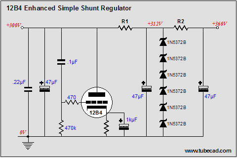
Enhanced simple shunt regulator
In this regulator, the 12B4 works to eliminate any AC perturbation at the output. Any signal at the output is relayed to the 12B4’s grid, where it is amplified negatively at its plate, thereby canceling the signal. In other words, when the B+ voltage climbs up, the 12B4 pulls down by conduction more; conversely, when the B+ voltage sags, the 12B4 lets go of some of its current conduction, pushing the B+ voltage higher. All in all, this is a nice, easygoing high-voltage regulator that neither offers strict DC regulation or ultra low AC output impedance. But for class-A line stage amplifiers, these failings do not offend too greatly.
A simple solid-state high-voltage regulator
The 1k resistor that attaches to the output sees a fairly constant 10V across its leads, which means that 10mA flows through it and, roughly, through the two 14.5k resistors, which helps set the fixed output voltage. The 10V zener works as the internal voltage reference and the two diodes protect the regulator at turnoff.
The new solid-state, high-voltage regulator design
In the schematic above, we see a simplified version of the TCJ high-voltage regulator (or would the “Belt and suspenders high-voltage regulator” be a better name?). The regulator puts out 290V of clean and drift-free voltage. The constant-current source provides a fixed current, which against a fixed resistance, defines a fixed voltage. Changing the current or the resistance will change the output voltage. The 0.1µF capacitor offers the OpAmp’s positive input an AC path to ground. The 50W power MOSFET serves as the pass device. The OpAmp provides the gain needed to drive the feedback loop and it must be unity-gain stable. The 0.1µF capacitor attached to the OpAmp’s negative power supply pin helps prevent the OpAmp from oscillating. This capacitor must be mount close to the OpAmp and its leads must be short. Fleshing the circuit out requires a few more parts.
First of all, this title is a bit misleading, as the regulator isn’t all that new; I built a similar high-voltage regulator twenty years ago. My old design used more parts to establish the high-voltage constant-current source (TIP50- and LM317-based). So, although I haven’t actually built this regulator, I have had much experience with its more complex predecessor. But before I would hook this regulator up to a high-voltage power supply, I would test it under much lower voltages. In the schematic below, we see reference voltage string of resistors shorted out by the added line in red. Our high-voltage regulator has been transformed into a fixed 10-volt regulator.
If the regulator fails the low-voltage output test, it isn’t likely to pass the high-voltage test. If it does pass the low-voltage test, I would hook it up to a regulated high-voltage power supply or a variac-controlled conventional power supply first, before hooking up the raw high-voltage DC power supply. Baby steps! If it doesn’t pass the low-voltage test, then the OpAmp is the most likely suspect. Try using an old, low-bandwidth OpAmp, instead of a new, wide-bandwidth, high-slew screamer. Sometimes less is more. If the OpAmp swap fails, then the power MOSFET should be examined. Its leads should be short and the gate-stopper resistor should be non-inductive, such as bulk-foil or carbon composition, and it should be placed close to the MOSFET’s gate. If none of these steps work, then the physical layout is probably to blame (this circuit really should sit on a PCB). Please send any feedback that you can on this regulator. If it works right off the workbench, let me know; if it oscillated no matter what you did, let me know. I hope to build up a working version soon and I will report my findings.
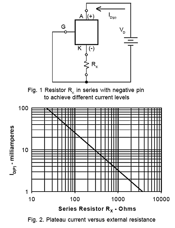
Setting the idle current on the IXCY 10M45S //JRB
|
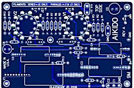
High-quality, double-sided, extra thick, 2-oz traces, plated-through holes, dual sets of resistor pads and pads for two coupling capacitors. Stereo and mono, octal and 9-pin printed circuit boards available.  Aikido PCBs for as little as $24 http://glass-ware.stores.yahoo.net/
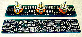
The TCJ Stepped Attenuator The center knob controls both channels, and offers six large decrements; the flanking knobs offer six fine decrements for each channel, creating a volume control and balance control in one easy-to-use stepped attenuator. This clever attenuator uses fewer resistors (only 32) than would be expected from a conventional 32-position stepped attenuator, as two series attenuators would need a total of 72 resistors; and two ladder attenuators would require 140 resistors. In addition, the PCB holds dual sets of resistor pads, one wide and one narrow, so that axial (composition, wire-wound, and film) and radial (thick-film and bulk-foil) resistors can be used without extra lead bending. Although designed to go with the Aikido amplifier, it can be used anywhere a high-quality attenuator is needed, whether passive or active. For example, it would make a first-rate foundation to an excellent passive line box. Visit our Yahoo Store for more details: http://glass-ware.stores.yahoo.net/
Only $12.95
Download or CD ROM www.glass-ware.com
The Tube CAD Journal's first companion program, TCJ Filter Design lets you design a filter or crossover (passive, solid-state or tube) without having to check out thick textbooks from the library and without having to breakout the scientific calculator. This program's goal is to provide a quick and easy display not only of the frequency response, but also of the resistor and capacitor values for a passive and active filters and crossovers. TCJ Filter Design is easy to use, but not lightweight, holding over 60 different filter topologies and up to four filter alignments: While the program’s main concern is active filters, solid-state and tube, it also does passive filters. In fact, it can be used to calculate passive crossovers for use with speakers by entering 8 ohms as the terminating resistance. Click on the image below to see the full screen capture.
Tube crossovers are a major part of this program; both buffered and un-buffered tube based filters along with mono-polar and bipolar power supply topologies are covered. Available on a CD-ROM and a downloadable version (4 Megabytes). Download or CD ROM
|
|||


.png)
.png)
.png)


| www.tubecad.com Copyright © 1999-2006 GlassWare All Rights Reserved |