| John Broskie's Guide to Tube Circuit Analysis & Design |
10 February 2009
Stimulus: It's Not What It Used To Be
So if I am often right, but too soon, might all of this be too drastic, too much real change for anyone to audaciously hope for? Perhaps. But I do know that it would actually stimulate real economic growth and greatly improve the quality of life in the USA. Instead, however, I expect us to follow the Obama economic plan of being wrong and too late. Recessions can be painful, but they are also often necessary, as nothing else allows business to reboot once it is stuck in an unresponsive program, such as the railway investment dead end in the 19th century or the dot.com bubble in the 90s. If we just let the economy reset itself, things would improve in a year or two. Instead, we want the same craziness that led to the current fiasco to continue forever. No nation has ever triumphed by suing itself silly and having most of its people work for the government.
Wait a Minute...
Getting Electronic Parts By the way, if you do not use OctoPart.com, you should. This site will search through many more electronic part suppliers than you can remember. For example, I performed a search for 5687s and Octopart revealed that an industrial instrument supply house had 8 NOS RCA 5687s for only $6 each collecting dust for the last 30 years. Think outside the the Mouser/Digi-Key box.
Back to Power Boosters
As we can see from the chart, a 1024W amplifier only puts out 32 times more voltage than a 1W amplifier. Worse still, our ears do not perceive it as being 32 times more powerful. I would still welcome only a voltage or current rating on power amplifiers, as it would help flatten the exponential climb. In other words, no one can hear the difference between a 60W and a 64W amplifier, which a voltage rating of 21.9Vrms and 22.63Vrms, respectively, would better help to reveal. The next step is to factor a loudspeaker’s SPL into the mix. If you double the output voltage, the SPL gains 6dB. For example, an 88dB efficient loudspeaker will put an SPL of 88dB at one meter with a 2.8Vrms input signal. Doubling the signal voltage to 5.6Vrms increases the SPL to 94dB and the wattage from the power amplifier goes from 1W to 4W. The following graph includes SPL.
Note how much power is required to get to 118dB. Also note how starting with a higher-efficiency loudspeaker, say 100dB, would require only a 64W power amplifier to reach the same 118dB SPL. On the other hand, an 82dB loudspeaker would need a 4096W power amplifier! (By the way, what is the limit to a loudspeaker’s efficiency? If I remember correctly, about 128dB SPL would equal unity power transfer.)
Now the interesting question is what happens if two 88dB loudspeakers were placed in series, effectively presenting a 16-ohm load to the amplifier, what would be the effective efficiency of the pair? If a solid-state or tube OTL power amplifier were used, each driver would see half of the 2.8Vrms signal, so each driver would lose 6dB in SPL, but at the same time we would have doubled the driver surface area, which would give rise to a +6dB boost; thus, we would end up where we started, 88dB for 2.8Vrms.
If both drivers are placed in parallel, each driver will still see the same 2.8Vrms, but the doubled surface area will deliver its +6dB boost, so the SPL will increase to 94dB. We didn’t just get something for nothing, as the current into the loudspeaker pair has doubled (4 ohms versus 8 ohms). Of course, if our amplifier can deliver the doubled current, we will gladly take the increase in SPL. Now what happens if we place four drivers in series/parallel, for a combined impedance of 8 ohms?
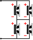
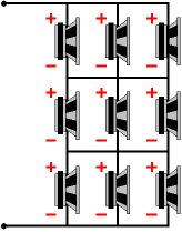
Each driver will see half the signal voltage, so each driver’s SPL goes down 6dB, but we increased the surface area by fourfold, so we gain +12dB of SPL, assuming that the drivers are close to each other and the frequencies reproduced are large relative to space between drivers. So, -6dB added to +12dB yields a final SPL increase of +6dB, so our normally 88dB SPL speakers will behave as 94dB cluster. In addition, the power amplifier delivers the same voltage and current into this cluster of drivers that it would into a single driver. The next 8-ohm combination of drivers is nine 8-ohm drivers, with three rows of parallel atop each other, as 8/3 x 3 = 8.
Each driver will now get its third of the power amplifier output voltage, so each driver will lose 9.5dB of SPL, but with nine times the radiating surface area, we gain +19dB in SPL, so the final SPL for 2.8Vrms will be +97.5dB, with our 88dB drivers. Okay, this is all interesting, but where are the tube power amplifiers with 2A3s or 300Bs? Where can I buy a “Where’s the tubes?” bumper sticker? We can now return to the idea of using a flea-powered tube amplifier with a big solid-state beast of an amplifier. If you are as old as I am, you will remember the huge fuss the Bose 901 loudspeakers created decades ago. Back then, when you told someone that you were an audiophile, they would more than likely instantly respond with, “Oh, you own Bose 901s!” I was never a fan, but then I was in the minority. Dr. Bose used exploding wires, if I remember correctly, to discern the ratio between direct and indirect sound from a point source, the imagined theoretically perfect loudspeaker polar dispersion pattern. His conclusion was that only 11 percent of the signal reaching our ears was direct, the rest coming from reflections. Thus, he placed one driver facing the listener and eight facing backwards. Now, imagine a modern day copy of the famous 901, with the same driver placement, but with the front-firing driver getting its signal from our 2.5W flea-powered champ and the remaining eight drivers configured as a 4-ohm cluster, driven by a 100W solid-state brute of an amplifier. In other words, our 2.5W has effectively become a 200W amplifier (4-ohm load for solid-state amplifier double power output). But won’t all that stinky solid-state power just overwhelm the bejeweled glory from the tube amplifier’s output? Perhaps, but I doubt it, as the ear will give the first arriving sounds precedence over the latecomers. This just might work and today’s full-range drivers are vastly superior to those made 30 years ago.
Since we are getting whimsical here, I will mention that I would like to build a line-source dipole loudspeaker that held nine full-range drivers (and one 98dB horn tweeter), which would allow switching between 8 ohms or 72 ohms, with all the drivers in series. Who the heck would want a 72-ohm loudspeaker? I would, as I could then build a simple OTL amplifier that would welcome the high load impedance. And at the flick of a switch, the loudspeaker would return to 8 ohms, for easier selling or to bring over friends house to try with their solid-state monsters. By the way, 88dB would still equal 88dB with the 72-ohm configuration; but with the 8-ohm configuration, +9.5dB boost in SPL would result. On the other hand, our OTL amplifier would certainly swing much more voltage into the 72-ohm load than any solid-state power amplifier, so effectively the tube amplifier play plenty loud. The Last Idea for Now
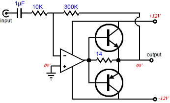
The two power transistors are turned off at idle, but when the OpAmp’s output voltage signal gets high enough they begin to conduct, greatly increasing the possible power delivery into the low-impedance headphones. At low signal levels, however, the transistors contribute nothing to the output signal. Think of them as turbo chargers. Now imagine a 1-ohm loudspeaker, such as the old Apogees. Such a loudspeaker will kill even the burliest of solid-state power amplifiers. Well, that actually isn’t true. All amplifiers can drive a 1-ohm load—they just cannot drive it very far. For example, if the power amplifier holds a 2A current limit, only 2Vpk will be possible into the 1-ohm speaker, which equals only 2W. But if we put in place some big power transistors, our 2A current swing could equal 25V of peak voltage swing into the 1-ohm load, which would equal 312W of power. Ideally, the transistors should reside in the 1-ohm loudspeaker’s cabinet, but such an arrangement would make hooking up the small power amplifier’s feedback all but impossible. And if the transistors fell outside the feedback loop, the distortion would be high, as the switching transition is a harsh one. Perhaps staggered arrays of MOSFETs would prove more effective at lowering distortion.
//JRB
|
Kit User Guide PDFs
E-mail from GlassWare Customers
High-quality, double-sided, extra thick, 2-oz traces, plated-through holes, dual sets of resistor pads and pads for two coupling capacitors. Stereo and mono, octal and 9-pin printed circuit boards available. Aikido PCBs for as little as $24 http://glass-ware.stores.yahoo.net/
Support the Tube CAD Journal & get an extremely powerful push-pull tube-amplifier simulator for TCJ Push-Pull Calculator
TCJ PPC Version 2 Improvements Rebuilt simulation engine *User definable
Download or CD ROM For more information, please visit our Web site : To purchase, please visit our Yahoo Store:
|
|||||||||||||||||||||||||||||||||||||||||||||||||||||||||||||||||||||||||||||||||||||||||||||||||||||||||||||||||
| www.tubecad.com Copyright © 1999-2009 GlassWare All Rights Reserved |


