| John Broskie's Guide to Tube Circuit Analysis & Design |
26 September 2009
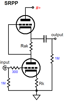
First SRPP, Then SRPP+
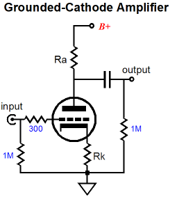
Had the output been taken at the bottom of resistor Rak, then there would be no push-pull, as the top tube and resistor Rak would effectively define a simple plate resistor and the circuit transforms into a simple variation on the grounded-cathode amplifier, with only single-ended operation.
The key point here, which eludes about 95% of tube fanciers, is that a simple plate resistor (or triode and resistor Rak) in a grounded-cathode amplifier can only increase beyond idle current conduction when the bottom tube does as well. In other words, when the bottom tube increases its conduction, the plate resistor sees a greater voltage across its leads and its current conduction increases correspondingly. But in an SRPP circuit, with the output taken at the top tube’s cathode, the top tube’s current conduction can increase, while the bottom tube’s decreases. Amazingly enough, the top tube's conduction can increase in spite of it seeing a smaller cathode-to-plate voltage. With the standard plate resistor, less voltage always means less current. In other words, the SRPP operation is a fundamentally different in functioning from the grounded-cathode amplifier. This is the key point: just because a tube circuit holds one tube standing atop another does not make that circuit an SRPP. The Broskie cathode follower, cascode, and White cathode follower, and the first and second stages of the Aikido all hold two tubes in series, but none of them is an SRPP. (If only I had a buck for every time the Aikido gets described as containing an SRRP input stage, I would be much richer. Absolutely nothing pushes and pulls in an Aikido's first stage.) Of course, if no external load attaches to the SRPP, it no longer experiences any push-pull operation, as the remaining single current path through the circuit will not allow a delta in current conduction to occur. In other words, an external load is not essential to a grounded-cathode amplifier, but it is to an SRPP. Just as in a Circlotron amplifier, the load makes all the difference.
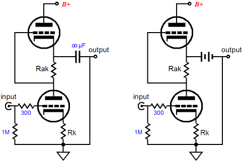
In fact, the best way to approach an understanding of the SRPP is to set the external load resistance to zero; that’s right, 0 ohms. Of course, directly shorting an SRPP’s output to ground would cause all sorts of problems in an actual physical circuit, so imagine that the a coupling capacitor with infinite capacitance is used or that a high voltage battery is used in place of the coupling capacitor. With such an arrangement, the anti-phase conduction between top and bottom triodes becomes obvious. As the bottom tube conducts more, greater will be the voltage drop across resistor Rak, which in turn will decrease the grid voltage on the top tube, thereby causing its current conduction to fall. If the top tube is conducting less and the bottom tube is conducting more, then the only current path for the latter’s increased conduction s the external load, which is zero in this example.
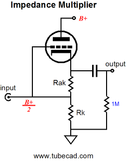
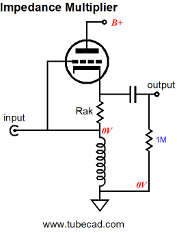
The SRPP’s Impedance-Multiplier Circuit
The above circuit looks a bit like a cathode follower, but it’s not a cathode follower, if for no other reason than that its input impedance is vastly lower than a true cathode follower’s. Note how the input attaches to both the tube’s grid and the resistor Rk. Here is a quick quiz: What would the input impedance be of the above circuit if the external load impedance were zero? The answer is Rak || Rk. Ok, that was too easy. What would the input impedance be of the above circuit if the external load impedance were infinity? The answer is [rp + (µ + 1)Rak] || Rk. Now the much harder question: What would be the input impedance with an external load impedance that falls between 0 and infinity ohms? The answer is much more difficult, but if we assume that resistor Rak had been carefully selected to provide impedance doubling with the selected tube and load resistance, then the answer is (2Rload + Rak) || Rk. By the way, the symbol “||” means in parallel with, so X || Y equals XY / (X + Y). In order to focus solely on the impedance-multiplier circuit, let’s replace resistor Rk with an inductor, a perfect inductance that displaces no DC voltage, as it holds no DCR. Notice how the choke eliminated not just the bottom tube (or large-valued resistor) but also the pesky DC offset at the input of the impedance-multiplier circuit. Now the input impedance of this circuit equals only Rak + 2Rload. No doubt some are wondering, why not just make a cathode follower out of the single triode and be done with it?
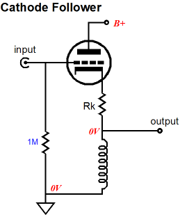
The cathode follower offers some desirable attributes, such as a lower output impedance and a ultra-high input impedance, in this example an input impedance of 1M. But the cathode follower cannot symmetrically swing beyond the idle current into the load impedance. For example, if the idle current is 10mA and the load impedance is 10k, the cathode follower can only swing +/-10mA or voltage swings of +/-10Vpk into 1k. the SRPP circuit, on the other hand, given the same load and idle current, can swing +/-20mA or voltage swings of +/-20Vpk into 1k, effectively quadrupling the power delivered into the load. Wait a minute, how is that possible? We got rid of the bottom triode but an inductor can only current-swing up to idle current? True enough, and I never knowingly try to break the laws of physics (and no laws are broken here). The impedance-multiplier circuit is not anything like a cathode follower, remember; its input impedance is low and depends on the amount of impedance multiplication and the external load impedance. So when this impedance-multiplier circuit swings negative 20V into the 1k load, thereby swinging -20mA, the inductance pulls -10mA and the signal source provides the extra -10mA. Conversely, when this impedance-multiplier circuit swings positive 20V into the 1k load, thereby swinging +20mA, the inductance undergoes no change in current flow from -10mA and the triode conducts +20mA and the signal source provides the extra +10mA, so the -10mA + 20mA + 10mA equals +20mA.
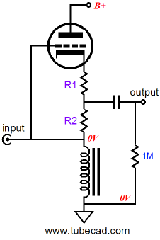
SRPP+ Versus Plain-Jane SRPP
Why is the extra resistor so important? It allows us to “tune” the SRPP to different load impedances. Just as we used two resistors to set the impedance-multiplier ratio in the idealized impedance-multiplier circuit, we also need two resistors with a tube-based impedance-multiplier circuit. As you might have guessed, because of the triode’s low transconductance, rp, and limited mu, the simple formulas for the idealized impedance-multiplier circuit must be substantially modified to conform to the tube’s actual functioning. By the way, the generic SRPP also held two resistances between the two triodes, but its R1 was invisible to those who only see with their eyes. (In a past life I must have been a Zen master or an American Indian medicine man, as such incomprehensible and paradoxical utterances come naturally to me.) Resistor R1 was implicit in the form of the top tube’s impedance at its cathode, which equaled rp/mu (1/gm). This impedance effectively created the missing R1. Thus, in order for R1 to have disappeared altogether, the top tube must have offered infinite transconductance; not likely. Solid-state power amplifiers come close enough for government work, but poor little triodes have a hard time mustering a maximum of about 40mA/V of gm. For example, a 6DJ8/6922-based Plain-Jane SRPP circuit holds an implicit R1 of about 100 ohms, as the triode’s gm is about 10mA/V. If Rak’s value were set to 100 ohms, the impedance-multiplier circuit within this SRPP circuit would effectively double the load impedance, as R1 and R2 (Rak) would be equal. (By the way, we can view any power amplifier’s transconductance as the inverse of its output impedance times its gain, no matter how complex or simple the amplifier, as long as it is a voltage amplifier. "Wait a minute," you may say, "I never see output impedance on the spec sheets, only damping factor." Damping factor is equal to the load impedance [usually 8 ohms] divided by the amplifier’s output impedance; thus an amplifier, with a damping factor of 80, has an output impedance of 0.1 ohms. If its gain is 10, then its transconductance equals 10/0.1, or 100A/V. Now you can see why a dead short at its output is so dangerous.)
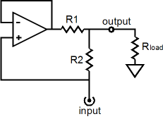
Let’s quickly review an idealized impedance-multiplier circuit. Resistors R1 and R2 set the impedance-multiplication ratio for the circuit. When R1 equals R2, the impedance-multiplier circuit will effectively double the load impedance. Our idealized impedance-multiplier circuit can swing huge voltage and current swings into a load while dissipating no heat at idle; it is ideal, after all. The tube-based SRPP is not so lucky, as it must run its internal impedance-multiplier circuit in a strict push-pull class-A mode, wherein the peak output current equals twice the idle current. So the tube-based version must strive for equal positive and negative current swings, which means that its optimal impedance-multiplier ratio is 2. Yet, we cannot simply make R1 and R2 equal, as the top triode’s cathode impedance must be added to R1’s value to get the “true” R1 value. (Interestingly, the bottom triode’s impedance at its plate only influences the impedance-multiplier circuit’s output impedance, but has no effect on the R1 and R2 values.) The tube-based impedance-multiplier circuit has to contend with the implicit contribution to R1’s value and its own rp and the load impedance influencing the results. So a universal impedance-multiplier circuit, one that is indifferent to the load impedance, is impossible to achieve with a single triode. Our idealized impedance-multiplier circuit did not suffer from this problem, as its power OpAmp presented no series resistance to R1, having an infinitely-low output impedance and a perfect unity gain. In other words, we will have to rely on formulas and a good amount of actual hardware tweaking to set R1 and R2 values within an actual SRPP+ circuit. But before we embark on this mathematical journey, lets examine differential impedance-multiplier circuits to get a better understanding of how this novel circuit functions.
Solid-State Impedance-Multiplier Circuit Variations
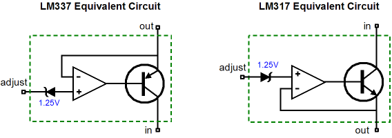
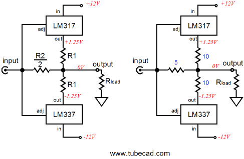
The following two impedance-multiplier circuits use the LM317 positive regulator and LM337 negative regulator as examples, but are in no way limited to these devices. In both examples, an impedance-multiplier circuit is loaded by a constant-current source, because the three-pin regulators are much like a single triode or transistor or MOSFET in that a single device must be operated class-A. Also in these examples, resistors R1 and R must be equal, as we want the impedance-multiplier circuit’s input and output to be centered at ground potential. Setting the idle current is as easy as the following formula implies: Iq = 1.25/R1 Once again, much like the tube-based SRPP circuit, if we want equal peak symmetrical output current swings, then R2 must equal R1. On the other hand, if we do not need the biggest symmetrical output current swings, we can set a different impedance-multiplier ratio. For example, let’s say we own an MP3 player that works well into its 32-ohm headphones, but grossly bogs down into inefficient 8-ohm headphones. Well, one of the below circuits set to an impedance-multiplier ratio of 4 would make a good candidate for helping the MP3 player along, as 8-ohm headphones would appear as 32-ohms headphones at the MP3 player’s headphone jack.
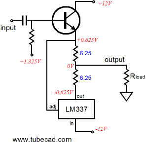
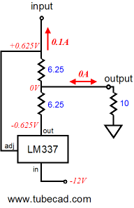
Maybe I am jumping ahead to quickly. Let’s back up a bit and examine the voltage and current relationships within an LM337-based impedance-multiplier circuit.
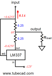
The circuit shown above is in its quiescent state, at idle, drawing 0.1A (or 100mA), blind to the external load, as the load draws no current. How can this circuit conduct with no path attached to its input that leads back to ground? It cannot conduct, but we can assume that it does attach to a signal source and that this signal source will provide a current path for the 0.1A of current, such as the following.
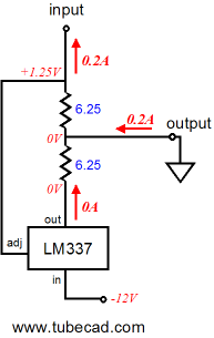
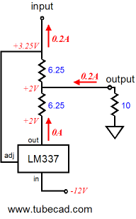
By the way, the transistor could be replaced by a FET, triode, pentode, MOSFET, IGBT… The two 6.25-ohm resistors combine to form a 12.5-ohm resistor that sets the idle current to 0.1A, as 1.25V/12.5 = 0.1A. Now, for the rest of the examples, assume that the transistor/triode/MOSFET is in place, but not shown. We also will begin with a load resistance of zero ohms, dead short to ground in other words. The following schematic shows the voltage and current relationships when the transistor increases its current draw from 100mA to 200mA. Note how the LM337 has been turned off, as any current flow through it will increased the voltage differential greater than 1.25V between its adjustment and output pins. The load (ground) does see 200mA of current flow through it up to through the top 6.25-ohm resistor then on through the transistor/triode/MOSFET to the +12V power supply rail. Note that the transistor only increased its conduction by 100mA over its idle current and the load experienced a 200mA current swing.
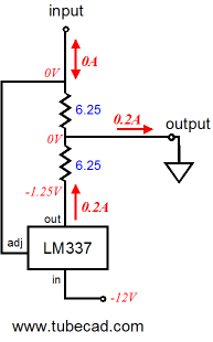
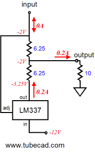
Next we will invert the current relationships.
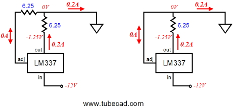
Now the transistor has been cut off and draws no current, leaving it up to the LM337 to increase its conduction to make up the difference. Note how the 200mA of current now flow in the opposite direction up ground. Also note how the same 1.25V voltage differential obtains between the LM337’s adjustment and output pins, as it has in all the previous examples. As far as the external load (ground) is concerned, a constant-current source of 200mA has just bridged it to the -12V power supply rail, which the following schematics make clear. Only one 6.25-ohm resistor sees any current flow, so we easily imagine that it has been replaced by a jumper wire.
Before reading further, please make sure you really understand what was shown in the previous paragraphs. Review how the 1.25V voltage differential is always present between the LM337’s adjustment and output pins and how the current changed direction through the external load. Ready? Okay, we now move on to examples that hold a 10-ohm external load.
At idle, nothing much has changed compared to the load-equals-zero example, as no current flows through the 10-ohm resistor. But when the transistor increases its current draw from 100mA to 200mA, the LM337 turns off and the 10-ohm load sees 200mA of current flowing through it, which develops a 2V voltage drop across the resistor.
Now we do the inverse and the transistor cuts off and draws no current, so the LM337 must increase its conduction to 200mA to make up the difference. Note how the current now flowing into the load reverses direction, as the impedance-multiplier circuit’s output swings down to -2V. Note how the output had remained stuck at zero volts when the load equaled zero ohms. The greater the load impedance, the bigger the voltage swings. At all times the same 1.25V voltage differential obtains between the LM337’s adjustment and output pins
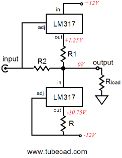
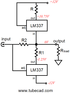
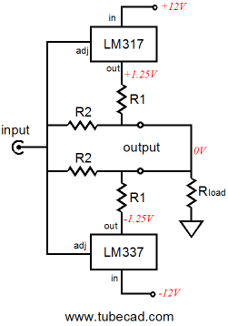
We have seen how we can make an impedance-multiplier circuit out of either positive or negative voltage regulator ICs. What would happen if we built one of each and then placed them in parallel, inputs and outputs tied together?
Note how we no longer need to supply the heavy idle current through a constant-current source or the signal source, as each impedance-multiplier circuit completes the current path for its partner. Also note how the two R2 resistors are effectively in parallel, which means that we can get away with just one resistor. In the schematic at the above left, we see the single R2 resistor in place; in the above right, we see some actual resistor values. By the way, if you recognize something that looks like a solid-state output stage in this topology, then the following schematic should look even more familiar.
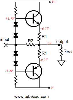
In the above circuit, two power transistors do all the work in the two impedance-multiplier circuits. The four diodes merely define voltage references of sorts to set the transistors idle current. The greater the number of diodes, the bigger the combined voltage drop and the higher the idle current through the transistors. The big problem that we always face with power transistors is getting the bias right, as the transistor’s base-to-emitter voltage changes with temperature, which can lead to thermal runaway and a smoking output stage. Many attempts have been made to devise clever circuits to overcome this problem, but my favorite is the 5-pin transistors from On Semi Corporation, as shown below. These transistors include a diode within their cases, which track the internal transistor perfectly; thus the marketing name, ThermalTrak™.
In the above schematic, six diodes are displayed: four external and two internal. These diodes set a high idle current of 1.9A through the output transistors, which will prove steady due to the internal diodes compensating for the power transistors drift. (The two 1kµF capacitors bypass the diodes to present a lower impedance to the transistor bases.) By the way, we could easily add more output transistors, as shown in the circuit below.
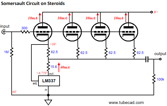
Note how only one pair of internal diodes is used. Also note how the emitter resistors have been doubled in value. Why? These resistors are effectively in parallel, so they effectively equal the single 1-ohm resistors. In other words, the same total current flows though the four-transistor and the two-transistor impedance-multiplier circuits, but in the four-transistor version, each transistor dissipates half the heat that the two-transistor version transistors do. In addition, the huge 2-ohm emitter resistors ensure that current hogging is extremely unlikely, as such large values provide a great deal of negative feedback. In other words, if one transistor tried to draw excessive current, the increase in current would provoke a bigger voltage drop across its emitter resistor, thereby lowering the transistor’s conduction. By the way, in Part One of this series, we saw a cathode follower loaded by an impedance-multiplier circuit made out of an LM337. (Remember the Somersault circuit.) Adding more triode in parallel would be easy. Each triode gets its own cathode resistor, whose value equals four times the R1 resistor value.
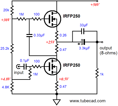
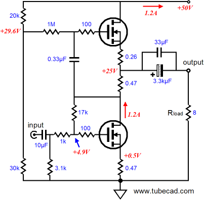
Zen Meets the Impedance-Multiplier Circuit First of all, the bottom IRFP250 is behind the steering wheel, as it is its variations in current conduction that will be magnified into the load impedance. In other words, its transconductance is driving the impedance-multiplier circuit loading it. And the bottom MOSFET’s transconductance is lessened and linearized by the unbypassed source resistor. The formula for the decrease in a MOSFET's gm because of an unbypassed source resistor is: gm' = gm / (1 + gmRs) So a change in input voltage will provoke changes in the bottom MOSFET’s current flow, which the top MOSFET within the impedance-multiplier circuit will double into the load impedance. In other words, this amplifier holds a current driven impedance-multiplier circuit.
The next power amplifier is configured as a voltage amplifier, with a fixed amount of gain and fairly low output impedance. The 1k input resistor and the 17k feedback resistor define a classic inverting-amplifier negative feedback loop. These resistors also serve to bias the bottom MOSFET. The huge coupling capacitor is required because of the low input impedance presented by the 1k and 3.1k resistors in parallel at the input. Using higher-value resistors will excessively limit the high frequency bandwidth. (Of course, if the amplifier were used in a bi-amped setup, wherein it powered the woofer, the truncating of the high frequencies may not prove such a liability; it may prove an asset.)
Note how, in both amplifier examples, the R1 and R2 resistor values do not match. Why? Like the triode, the MOSFET suffers from limited transconductance, so the impedance at its source is not zero. Thus, its source impedance must be subtracted from R1’s ideal value (0.47 ohms, in this example).
Next Time
//JRB |
Kit User Guide PDFs
E-mail from GlassWare customers:
And
High-quality, double-sided, extra thick, 2-oz traces, plated-through holes, dual sets of resistor pads and pads for two coupling capacitors. Stereo and mono, octal and 9-pin printed circuit boards available.  Aikido PCBs for as little as $20.40 http://glass-ware.stores.yahoo.net/ Only $19.95
Download or CD ROM
|
|||


| www.tubecad.com Copyright © 1999-2009 GlassWare All Rights Reserved |