| John Broskie's Guide to Tube Circuit Analysis & Design |
06 October 2009
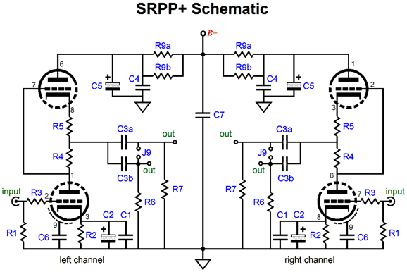
This should be the last installment on the SRPP and SRPP+ circuits—for a few months at least. The key point I hope that I have made is that the SRPP holds two sub-circuits and that one of the two, the impedance-multiplier circuit, is quite interesting, if for no other reason that so few knew it was there in the first place. The impedance-multiplier circuit, as topology (as a basic-circuit function), is little known. If anyone has mentioned it in the audio press, audioXpress et al, I haven’t seen it. A search of www.diyaudio.com for “impedance multiplier” yielded only five results, four of which dealt with a transistor’s current gain and one referred to my blog number 172. On the other hand, searching through patent applications does deliver many authentic hits, although few of the patented impedance-multiplier circuits concern audio. Thus you see my motive for deracinating the impedance-multiplier circuit from the SRPP. Ripped from its accustomed hiding place, we can evaluate its advantages and pitfalls in isolation.
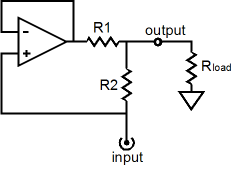
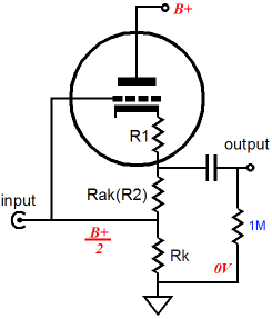
The idealized impedance-multiplier circuit shown above may not look much like the tube-based impedance-multiplier circuit shown below, but they both perform the same function: they enlarge the apparent load impedance to the signal source that drives the impedance-multiplier circuit. Compare both schematics and note how both the OpAmp’s non-inverting input and triode’s grid see the input signal, neither inverting the phase, both realizing 100 negative feedback and unity gain. Also note how the tube-based impedance-multiplier circuit’s resistor R1 is implicit in the impedance presented by the triode’s cathode. One way to visualize a cathode follower’s operation is to imagine that its triode is made up of a unity-gain amplifier with a resistance equal to the triode’s rp/mu in series with its output at its cathode. This resistance is also equal to the inverse of the triode’s transconductance.
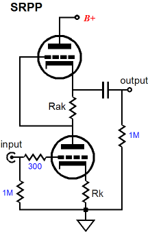
This implicit “resistor” must be included in any calculations of an SRPP design. With a generic SRPP circuit, we can only change resistor R2’s value, so R2 and the external load resistance must be manipulated to yield optimal performance. For example, the following formula tells us what the optimal load impedance is for a given triode and Rak value: Rload = (muRak – rp) / 2 Thus, if we use a 6H30 with 250V B+ power supply and 300-ohm cathode and Rak resistors (mu = 15.4 and rp = 1380), the optimal load impedance will be 1620 ohms, which is great if that is the load we wish to drive. But what if we planned on driving 300-ohm headphones instead? Then we would use the following formula which gives the optimal Rak value for a specified triode and load impedance: Rak = (2Rload + rp) / mu Returning to our example, Rak should equal 129 ohms. Wonderful, except that such a low cathode resistor value will result in 37mA of idle current, which against the 250V B+ voltage, heats the triode beyond its dissipation limit.
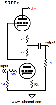
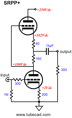
The SRPP+ allows us to keep the 300-ohm cathode resistor and still optimally drive the 300-ohm headphones. By setting R1 to 85 ohms and R2 to 215 ohms, a total of 300 ohms exists between triodes, so the SRPP+ will bias up exactly the same as a generic SRPP, drawing only 20mA, but nonetheless optimized to drive the 300-ohm headphones. The following formulas give us resistor R1 and R2 values: R2 = rp/2mu + Rload/mu + Rk/2 R1 = Rk – R2 So the first step is to specify both the cathode resistor Rk’s value and load impedance. If R2’s value becomes greater than Rk’s value, then the SRPP+ cannot be optimized to work with the selected Rk value and triode. On the other hand, the SRPP+ can be optimized to work into 0 ohms. Zero ohms! Why would anyone want to drive 0 ohms? Well, a 32-ohm load is dang close to 0 ohms, as far as a little triode is concerned, and an ammeter’s coil might have a DCR of 0.001 ohms. Continuing with the example of a 6H30-based SRPP+ circuit intended to drive headphones, but with a 32-ohm load and a B+ of 200V and an idle current of 20mA and Rk equal to 220, resistor R2 should equal 155 ohms and R1, 65 ohms, as the 6H30’s rp equals 1310 and its mu equals 15.4 at 20mA at 100V from cathode to plate. In this example, the 32-ohm makes a small contribution; but with a 600-ohm load, the ratio between R1 and R2 changes quite a bit more, as R2 would equal 172 and R1, 48 ohms. The idealized OpAmp-based impedance-multiplier circuit can swing both huge voltage and current swings into a load while dissipating no heat at idle, running as it does in perfect class-B mode; it is ideal, after all. The tube-based SRPP and SRPP+ circuit is not so lucky, as it must run its internal impedance-multiplier circuit in a strict push-pull, class-A mode, wherein the peak output current equals twice the idle current. If the bottom triode cuts off completely, it can no longer steer the top triode. Interestingly, the bottom triode’s impedance at its plate only influences the impedance-multiplier circuit’s output impedance, but has no effect on the R1 and R2 values, even if the bottom triode were replaced by a pentode. The bottom tube’s impedance at its plate will alter the output impedance seen by the load. The lower the impedance at the plate, the lower the output impedance. The plate-load impedance seen by the bottom triode is equal to 2Rload + R2, which allows us to compose the formula for the gain of an SRPP+ circuit, wherein the bottom triode’s cathode resistor is bypassed (or replaced with an LED) and the load is substantially lower than the triode’s rp. Gain = mu(2Rload + R2) / (2Rload + R2 + rp) With the cathode resistor left unbypassed (much better sounding), Gain = mu(2Rload + R2) / (2Rload + R2 + rp + [mu + 1]Rk) When the load impedance is high, the gain equals roughly mu/2. The SRPP+ performs best at driving fairly low impedances, however, as it functions like a small push-pull voltage/current amplifier of sorts. An ideal load would be a 600-ohm L-pad or series attenuator or low-input-impedance solid-state power amplifier, such as the Zen, or headphones with a flat-impedance plot. In fact, a small 1W OTL power amplifier could be made if a 600-ohm loudspeaker were used. (These speakers were once made for ham radio use.) Or with a 600:8 ohm step-down output transformer, the mighty 1W OTL could power 8-ohm loudspeakers. The obvious alternative is headphones, as many great-sounding headphones come with 250-2k impedances—such as those from Beyerdynamics and Sennheiser—that preclude their use with most MP3 players, most of which were designed with 16-32 ohm headphones in mind. If the load impedance is not flat, however, the SRPP+ circuit's relatively high output impedance will result in a non-flat output: as the impedance rises, so will the output, as the impedance drops, so will the output.
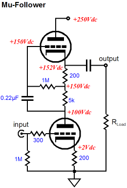
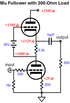
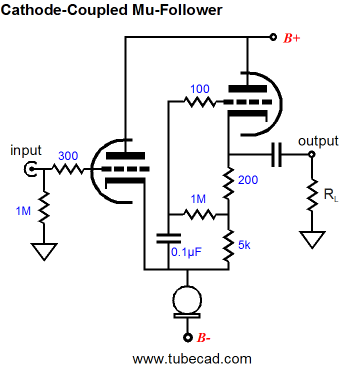
The Mu Follower Using a simple line-stage amplifier that will work into a high-impedance load, say 47k to 1M, the SRPP-type circuits prove only very good, not stellar performers, as they have relatively low gain and high output impedance and only fair PSRR (about -6dB with an infinite load impedance). Improving the SRPP’s performance in a line-stage amplifier application will require more parts, at the very least the addition of a battery.
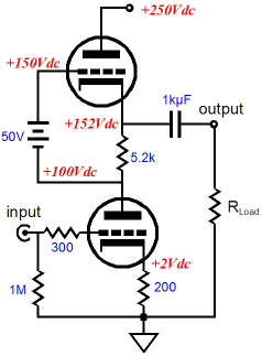
The battery allows us to use a much larger-valued Rak resistor; in the example above, the resistance is 26 times larger than the cathode resistor value. This increased resistance alters the circuit performance in several key ways: the output impedance drops, the distortion falls, and the PSRR figure improves dramatically. What’s not to like? Well, as so often proves the case, we gained much, but we also lost some. The loss takes the form of less potential current delivery into the external compared to the SRPP and SRPP+ circuits. Roughly put, the larger resistor Rak becomes, the closer the mu follower comes to the idle current as the peak current swings. In other words, with a well-designed SRPP-type circuit we can get close to twice the idle current into the external load resistance, whereas an optimally-designed mu follower’s peak current delivery equals the idle current. Now, in the typical line-stage amplifier application, wherein the external load resistance is a high 47k to 1M, high current delivery is not that important.
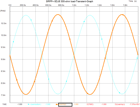
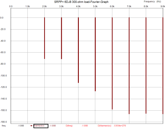
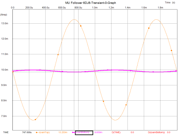
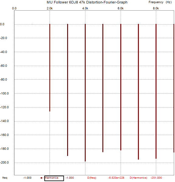
But if heavy current swings are needed, the SRPP and SRPP+ circuit works surprisingly well, considering how few parts are needed. The following graph shows the simulation results in SPICE from the circuit shown above, displaying the current swings within both triodes in the circuit that holds a 6DJ8 and has been optimized to work into a 300-ohm load. And the graph that follows shows the distortion harmonics for the same 1Vpk @1kHz into the 300-ohm load.
These are quite respectable results, showing less than 0.1% distortion, with high harmonics bottoming at -160dB. Also note how well balanced the current swings are within the two triodes. Of course, these results are only from simulations and SPICE triode models are guilty of exhibiting perfectly consistent amplification factors and perfectly matched triodes, neither of which occurs in reality. Nonetheless, the same SPICE failings apply to the following graphs from simulations on a mu follower with the same load and 1Vpk voltage swing at 1kHz, so we are comparing apples to apples, albeit simulated apples.
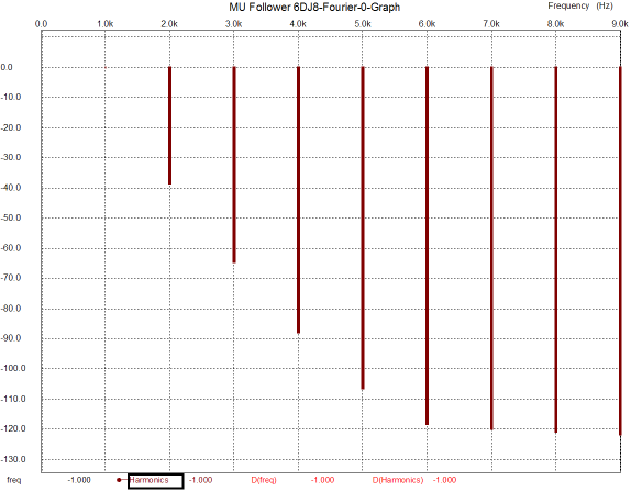
The current swings come close to matching our expectations, with the top triode swinging 50 times more current than the bottom triode. Thus, as far as the bottom triode is concerned, the load is now 50 times greater in impedance (plus the 5200-ohm Rak resistor makes for about a 20k plate load in spite of the 300-ohm load). The distortion is fair, coming in at a tad more than 1%, which isn’t bad when you consider how brutally-low a 300-ohm load is to small triode. Let’s pause and reflect on how odd the results are, as the mu follower should have killed the SRPP+, as it offered far better specifications, with much higher gain and much lower distortion and output impedance. What happened? It’s as if Woody Allen beat Arnold Schwarzenegger in an arm-wrestling match. (By the way, did you know that in Hollywood plastic surgeons work overtime giving men bicep, triceps, calf, and buttock implants? Making the weak appear strong, now there is a motto.) Well, what happened was that the SRPP+ was optimized for the 300-ohm load, the mu follower wasn’t. Given a high-impedance load, say 47k and 1Vpk, the mu follower will deliver staggeringly good performance, far better than the SRPP+, as the following graph shows.
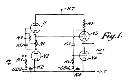
Crazy good results. Distortion is below 0.0001% and consists primarily of second harmonics. Yes, yes SPICE is not reality; but even if reality were ten times worse, those results would also amaze. Now you see why Chris Paul made such a big deal out of the mu follower back in the 1980s in Audio Amateur magazine. By the way, I have been corresponding with Chris and he has helped me see how I have been blind to many of the practical aspects of the mu follower circuit. Or rather, he has helped see that I have come to the mu follower and SRPP circuit from an entirely different direction or perspective than most. Back in the late 1970s, I was in the thrall of my silly, but glorious-sounding Sennheiser HD-414s. My little 6DJ8-based SRPP OTL headphone amplifier would bring tears to the eyes of solid-state-loving audiophiles. So my concern was primarily current delivery. (Then when I bought my Stax Lambda Pro electrostatic headphones, concern changed to huge voltage swings.) This application, a small OTL power amplifier of sorts, forced me to concentrate on delivering power. But not everyone needs to deliver huge current swings in to low-impedance loads. If the load is modest, the mu follower has much to offer; so much so, in fact, that I regret not adding a mu follower configuration on the SRPP+ PCBs. If only I had corresponded with Mr. Paul prior to laying out the boards. By the way, how can we retain the mu follower’s stellar performance and still deliver big current swings in low-impedance loads? Well, back in 1953, V. J. Cooper and collogues patented a Stabilized Thermionic Amplifier, US patent 2,661,398.
Mercy, a mu follower cascaded into a White cathode follower. The White cathode follower, if optimally designed, will deliver up to twice the idle current into a load. If less current is needed, the following circuit is also a contender.
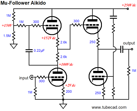
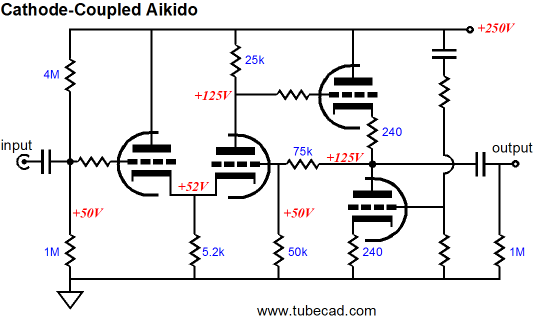
Mu follower meets Aikido. The Aikido cathode follower allows the little power-supply noise that appears at the output to be nulled and greatly unloads the mu follower, as the Aikido cathode follower’s input impedance is vertiginously high. Which also explains why the mu follower’s output is taken in between the two high value resistors and not at the top triode’s cathode or the bottom triode’s plate: mu follower output signal is pretty much equally present at all three take off points, as mu follower undergoes very little current fluctuations in the presence of an input signal. Of course, an extra internal coupling capacitor could be used instead. By the way, since I am so weary of hearing how the Aikido circuit is some sort of SRPP derivative, let point out that the Aikido’s input stage is not an SRPP stage. And while I am at it, let point out that it’s the Aikido second stage that defines it as an Aikido circuit. For example, the following is also an Aikido circuit.
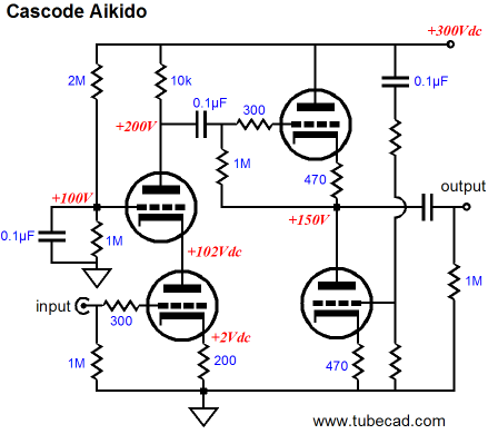
In the above schematic, we see a cascode input stage driving an Aikido cathode follower. The cascode delivers huge gain, far in excess of the triode’s mu; but the price we pay is an almost nonexistent PSRR figure. And the Aikido cathode follower nulls power-supply noise and offers low output impedance. Since we are in mind-stretching mode, let’s review another Aikido circuit.
As you might have guessed, given an infinite amount of time, pencils, and paper, I will come up with an infinite number of circuits. The sad part is that I have plenty of pencils and paper, but not so with time. So I had better stop here and promise a fourth installment on the SRPP-type and impedance-multiplier circuits. But let me leave you with something to ponder.
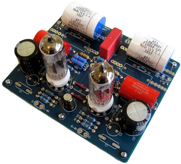
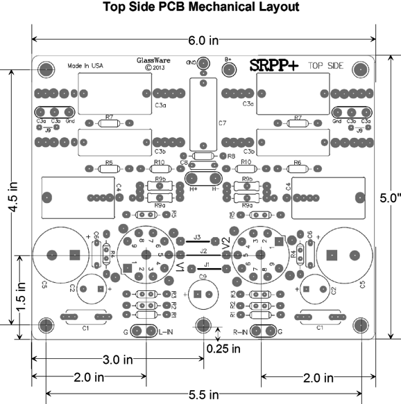
SRPP+ PCB
PCB layout:
//JRB
|
E-mail from GlassWare Customers
High-quality, double-sided, extra thick, 2-oz traces, plated-through holes, dual sets of resistor pads and pads for two coupling capacitors. Stereo and mono, octal and 9-pin printed circuit boards available.  Aikido PCBs for as little as $24 http://glass-ware.stores.yahoo.net/
Support the Tube CAD Journal & get an extremely powerful push-pull tube-amplifier simulator for TCJ Push-Pull Calculator
TCJ PPC Version 2 Improvements Rebuilt simulation engine *User definable
Download or CD ROM For more information, please visit our Web site : To purchase, please visit our Yahoo Store:
|
|||


| www.tubecad.com Copyright © 1999-2009 GlassWare All Rights Reserved |